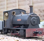

Learning from my experience last time, this time it was neater, easier and quicker to do. Quick note though that the wiring and RX and battery is not done as yet, so please ignore the stray wires

I used a Hitec HS-125MG thin wing servo under the cab floor for the regulator. This involved using my dremel to start a hole for the linkage, the filing it out to size. Once that was done, I just drilled two 1.6mm holes in the appropriate marked out place, tapped them out to 2mm thread, then put the servo in with two 2mm screws from the bottom, they hardly poke out into the cab, if they had have done, they would have been cut down to size. The do the initial hole I did remove the gas tank, gas pipe and inlte nozzle, as well as the steam pipe and lubricator. It just made things safer to work on rather then let the dremel run away and go through a pipe.
The forward / reverse servo was more difficult. For this I made up a servo holder out of brass and silver soldered it up. The brass was them drilled and tapped for the servo @ 2mm, and the bottom was also drilled and tapped to attach it to the loco. Careful consideration was given to allow the servo to fit under the cover with as little cutting of the cab work as possible. This time I managed to slant the servo in on the holder to tuck it tighter uner the boiler, giving me the oppertunity to leave the forward / reverse lever in the cab, which now operates with the servo. For this servo I used a Hitec HS-81MG which I had laying around from my RC flying days.
I have included a few pictures below so you can see what the job involves. If anyone has any questions or would like some more pictures so they can do the same to theirs, then please ask and I will see what I can do. Please note that the brass dust you can see in some of the pictures have not been cleaned up as yet, but are also not as easy to see by eye without the flash of the camera.


