TVT Guards Van

Discussion of Rolling Stock related topics should go here
Post Reply
User avatar
GTB
Driver
Driver
Posts: 1690
Joined: Sat Mar 05, 2011 2:46 pm
Location: Australia

TVT Guards Van

Post by GTB » Wed Feb 01, 2012 2:17 pm

The first product of the TVT rollingstock building program is a small 4 wheel brake van.

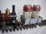
The model is built on my standard wagon underframe and also has working brakes, but to a different pattern to other underframes. The bodywork was built from polystyrene sheet, which works well in this application. I've been scratchbuilding models using polystyrene sheets for about 40 years, but that was in HO scale and this one is a lot bigger than anything I've previously built....... :shock:

The picture shows the underframe fitted with it's working brake gear and the footboards. A real guards van would have had a screw brake inside, but without access to the interior, the brakes are operated by the rod running off to one end. This has a notch that fits over a pin to latch it in the on position. The construction is otherwise as described in the TVT wagon underframe thread.

Image

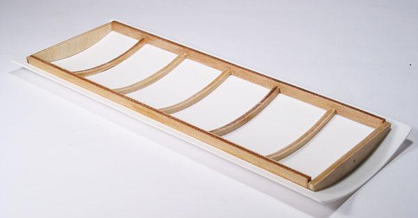
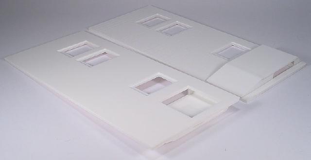
This photo. shows the three layers of polystyrene sheet used to construct the van sides. Some detail won't be clear, as it isn't easy to photograph the white sheets.

The inner 0.060" layer has an opening for the glazing. The middle 0.020" layer has a smaller opening which simulates the window frames. The outer 0.040" layer has the board and door detail scribed on with an Olfa P Cutter and larger window openings, so the window frames of the middle layer are recessed. The ends are made from two layers of 0.060" sheet, again with the boards scribed on. The floor isn't shown, but was made from 0.060" sheet.

Image

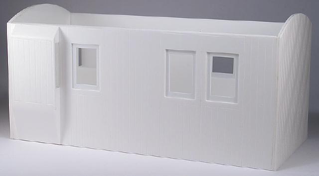
This photo. shows the assembled body sides, including the side lookouts. The lookouts are built up from various thickness pieces, with an opening in the van side so the glazing can be fitted after painting.

I use Methyl Ethyl Ketone for glueing polystyrene in most cases, but it evaporates to rapidly to use for laminating large sheets. To successfully laminate the sides and ends I used Microscale Micro Weld, which is actual made from d-Limonene and is much better for laminating parts out of polystyrene sheet.

Image

The next photo shows the fully assembled body, before detailing.

Image

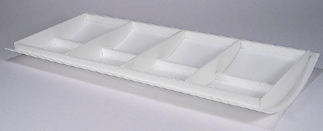
This photo shows the roof, with the 0.040" polystyrene sheet roof curved and then fitted to a bracing frame, which is my usual design method when I want to make the roof removable.

Image

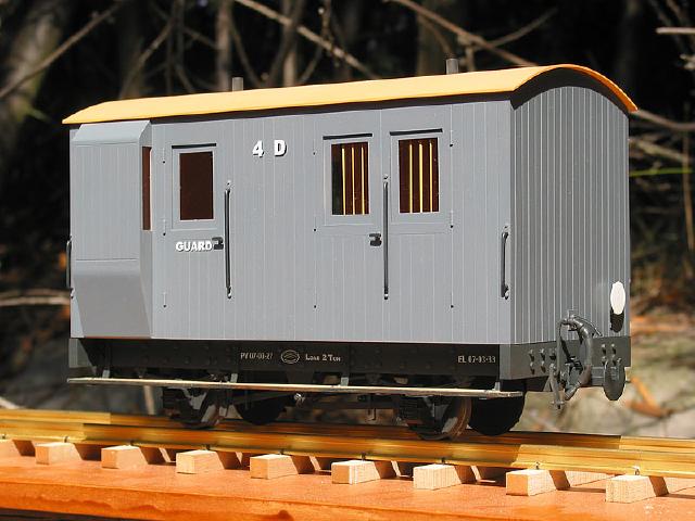
The next pic. shows the detailed body fitted with door hinges and handles, handrails, lamp irons and the roof detailed with a stove chimney and lamp tops, all fitted to the underframe. The air brake hoses were caught up in the Christmas mail jam when the photo was taken, but luckily turned up just before the underframe was painted.

The model breaks down into roof, body and underframe for painting. This also gives access to the interior so the glazing and window bars can be added after painting, without the need for masking. The floor is held to the underframe with several screws inside the body screwed into parts of the underframe. The roof is held on by long bolts that pass through the floor and screw into the roof frame. These were made by threading each end of a piece of 1/16" brass rod and soldering a brass nut on one end to make a very long hex head 10BA bolt.

Image

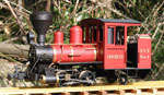
The final photos. show the finished model sitting in the back 'garden' in late afternoon sunshine. For those suffering through a northern winter, the temperature in the shade at the time the photos were taken was 28C. It was 32C in the workshop....... :roll:

Image

Image


TVT History

With the TVT being a semi-government organisation and the State of Victoria being generally of the protectionist persuasion (unlike the free trading riff-raff over the river), it was inevitable that as much capital equipment as possible would be ordered from Victorian firms.

Baldwin had won the locomotive order based on short delivery times, as the Phoenix Foundry in Ballaarat were busy with a large VR order for broad gauge locos.

By the time the TVT was built, the VR were building their own rollingstock, but some of the firms that had built rollingstock in the past were still around and were invited to tender. The successful supplier was G. F. Pickles & Sons, who were a large builder of horse drawn vehicles and operated the splendidly name American Steam Carriage Works located in Sandhurst in Central Victoria. Their works were located in the centre of town, so it is assumed the TVT rolling stock was delivered by horse team to the VR station and shipped by rail to the TVT in Gippsland.

As Pickles had previously only built VR rolling stock, the TVT order was based on VR practice and the TVT D vans had some resemblance to VR D vans. The main difference being the substitution of the birdcage type lookout on a VR van with side lookouts on TVT vans.

Like their VR counterparts, the D vans rode very badly when they were at the back end of a long goods train and were unpopular with the guards, although they at least had a stove, which VR goods guards didn't get until the '50s. They were never replaced though and lasted until the railway was closed down in the early 1950's.

Authors Note.

The company of G. F. Pickles & Sons did actually exist and traded for many years as carriage builders in Sandhurst, now known as Bendigo after a name change in 1890. They disappeared around 1930, presumably from the combined affects of the Great Depression and the coming of motor vehicles. All long before I was growing up in the district, but that's why I chose their name to go on TVT rolling stock builders plates.

They did actually use the business name of 'American Steam Carriage Works' in the late 19th Century, which presumably meant the factory was originally equipped with US made steam powered machinery. They also used the name 'Sandhurst Rolling Stock & Carriage Manufacturing Company' for a time when they were building rolling stock for the VR.

Regards,
Graeme

SapperAnt

Post by SapperAnt » Wed Feb 01, 2012 7:20 pm

Wow. Simply jaw-droppingly stunning.

spooner

Post by spooner » Wed Feb 01, 2012 7:26 pm

Excellent work.CME should be prod.

invicta280
Trainee Driver
Trainee Driver
Posts: 675
Joined: Wed Sep 21, 2011 9:24 pm
Location: kent england

Post by invicta280 » Wed Feb 01, 2012 9:27 pm

excellent workmanship

Pendo Pilot

Post by Pendo Pilot » Wed Feb 01, 2012 9:32 pm

Oh my!! That is something else. The underframe iteslf is a work of art & the body is amazing. Lovely modelling indeed.

Narrow Minded

Post by Narrow Minded » Wed Feb 01, 2012 10:19 pm

Top Drawer! :D

User avatar
tom_tom_go
Driver
Driver
Posts: 4824
Joined: Wed Feb 23, 2011 3:08 am
Location: Kent, UK
Contact:

Post by tom_tom_go » Thu Feb 02, 2012 12:50 am

You could start giving the usual brands a run for their money if you made them as kits!

Cheers,

Tom

User avatar
robc_wa
Trainee Fireman
Trainee Fireman
Posts: 106
Joined: Wed Jun 08, 2011 11:41 am
Location: Perth, Western Australia

Post by robc_wa » Thu Feb 02, 2012 7:18 am

Absoluely magnificent! Dare I ask how many hours went into it?

Rob

User avatar
Gremlin
Trainee Driver
Trainee Driver
Posts: 695
Joined: Sun Feb 08, 2009 2:46 pm
Location: Kent

Post by Gremlin » Thu Feb 02, 2012 11:34 am

new nice work indeed, can fully appreciate the time involved, super finish.

User avatar
Steven.T
Fireman
Fireman
Posts: 410
Joined: Sun Mar 13, 2011 5:56 pm
Location: Stockton

Post by Steven.T » Thu Feb 02, 2012 5:56 pm

Any chance you could do a write up of how you made the bracing for the roof? I'm struggling with my I.P. ones and need to make them removable!

Thanks
Steven

User avatar
GTB
Driver
Driver
Posts: 1690
Joined: Sat Mar 05, 2011 2:46 pm
Location: Australia

Post by GTB » Fri Feb 03, 2012 11:00 am

robc_wa:65843 wrote:Dare I ask how many hours went into it?
No real idea, as I've never kept track of the hours taken to build a model, it just depresses me......

The work was spread over 6 weeks or so, but I can't imagine I'd build one in less than a week of solid work, so 30+ hours at a guess.

Graeme

User avatar
GTB
Driver
Driver
Posts: 1690
Joined: Sat Mar 05, 2011 2:46 pm
Location: Australia

Post by GTB » Fri Feb 03, 2012 11:39 am

ste234:65868 wrote:Any chance you could do a write up of how you made the bracing for the roof? I'm struggling with my I.P. ones and need to make them removable!
Probably easier to see on this roof from an IP railcar kit. The guards van roof is the same construction, just the framing was done with polystyrene instead of plywood.

Image

The basic process is to make the frame first.

- cut a couple of pieces of sheet that are a snug fit between the sides. Check at both ends, they may not necessarily be the same.

- Hold a piece against the end and use a pencil to mark the top curve from the end. Again, this may not be quite symmetrical, so mark the sheet where it will fit against the end. For a passenger car, where they can be seen, it is worth cutting them to a curved shape like the railcar roof so they look like the carlines in a real carriage roof.

- cut and sand the curve until it matches the vehicle end, cut off the part and mark another one, then repeat until you have enough formers. I usually put one every 50mm or so along the roof, or put them between each window in passenger carriages.

- cut two strips to form the sides of the framing and cut them to length so they are a snug fit between the roof frame ends. Chamfer the top of these so they are the same angle as the roof. The width of the strip will depend on the vehicle. If it has windows then that sets the width, otherwise make them about 6mm wide. Glue them to the frame ends and leave overnight to reach full strength.

- take the other 'carlines' and cut them to a snug fit between the side rails, then glue in place.

- if you can't easily see the ceiling, to add extra strength, it is worth making all the 'carlines' deep like the end ones and fitting a few straight pieces between each 'carline' along the centre of the roof. This also gives something solid to screw lamp tops, vents etc. in place. The guards van roof is of this type.

Fit the roof to the frame when you are happy with the way the frame fits in the body.

- first curve the roof. I used 40 thous. polystyrene sheet, which is what IP usually supplies in current kits. I find I can set a curve into it, by drawing it over the edge of the workbench until it is curved to a slightly sharper radius than needed, so it won't try and lift away from the edges when fitted.

- another alternative is to laminate the roof from two thicknesses of 0.020" which is much easier to curve.

- glue the curve polystyrene into place.

If you have been careful, the roof will be a good fit and will just sit in place with friction, so you can access the inside of the body. Unfortunately, some people insist on picking up models by the roof edge, instead of the underframe. Shouting sometimes helps, but usually you have to fix the roof in some way.

If it is a loose fit, then a couple of small screws can be run through clearance holes in the end of the body into the roof frame to keep everything in place. In the case of the IP railcar, the headlight screws into place and traps the roof frame.

You can also arrange some sort of clip at one end, so only one end needs screws. In the garden scales it is hard to find screws long enough to pass through the floor and up to the roof, unless you have the equipment to thread pieces of rod. If the sides of the model tend to bow out, you can also stop this by fitting a clip arrangement halfway down each side so the sides are held against the longitudinal frame members.

Hope that helps...

Graeme

User avatar
Steven.T
Fireman
Fireman
Posts: 410
Joined: Sun Mar 13, 2011 5:56 pm
Location: Stockton

Post by Steven.T » Sat Feb 11, 2012 1:52 pm

Brilliant, Thanks Graeme!

User avatar
Keith S
Driver
Driver
Posts: 1666
Joined: Thu Feb 24, 2011 11:44 pm
Location: Canada

Post by Keith S » Wed Feb 15, 2012 9:17 pm

Hi Graeme,

You mentioned in one of your other threads that you used "a plumbing part" to make your brake shoes. I am going to need brake shoes soon and I was wondering if you could elaborate on what kind of thing you made them out of?

I'm currently building an IP brake van, but I'm embellishing it with brake gear and an interior that I am trying to fabricate myself.

User avatar
GTB
Driver
Driver
Posts: 1690
Joined: Sat Mar 05, 2011 2:46 pm
Location: Australia

Post by GTB » Thu Feb 16, 2012 1:48 pm

Keith S:66533 wrote:Hi Graeme,

You mentioned in one of your other threads that you used "a plumbing part" to make your brake shoes. I am going to need brake shoes soon and I was wondering if you could elaborate on what kind of thing you made them out of?
Luckily I haven't emptied the workshop rubbish bag lately and the label was still in there. ;)

The ones I use are a Bush Tube No. 4 25mm OD x 25mm MI. The large ones have an octagonal nut, not the hex shown in the supplier photo. They require access to a lathe to turn them into brake shoes.

http://www.oschin.com/product05-2.asp

I bore them out to wheel dia., part off two rings from the octagonal bit, drill pivot holes adjacent to each point, then cut the ring into 8 segments.

Image

One fitting is large enough to make two rings, which works out to 16 brake shoes for a couple of dollars.

I'd imagine you could also do it with back rings, but my local hardware didn't have octagonal ones that were of suitable size.

Graeme

User avatar
Keith S
Driver
Driver
Posts: 1666
Joined: Thu Feb 24, 2011 11:44 pm
Location: Canada

Post by Keith S » Thu Feb 16, 2012 1:58 pm

Thanks, Graeme. That is very clever. I'll have a snoop around the hardware store and see if there is anything like that here.

User avatar
GTB
Driver
Driver
Posts: 1690
Joined: Sat Mar 05, 2011 2:46 pm
Location: Australia

Post by GTB » Fri Feb 17, 2012 12:54 pm

Keith S:66552 wrote:Thanks, Graeme. That is very clever. I'll have a snoop around the hardware store and see if there is anything like that here.
Not an original idea. Saw it in one of Peter Jones books i think.

Also try a plumbing supply shop, if you have any nearby........

Graeme

Post Reply

Who is online

Users browsing this forum: No registered users and 3 guests