Hullo David,
I'll do my best with the information shown, some of the below is extrapolated from what I can see.

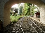
- Netta foot plate marked.jpg (1.95 MiB) Viewed 39812 times
1. Up here is the manifold - the highpoint on the boiler where dry steam can be tapped off for the controles. Mounted on the manifold is the whistle valve. Looks to me like the whistle is connected to the pipe that comes off on the top right.
2. The regulator valve - the handle is connected to a shaft that runs along the boiler to a valve under the dome. On locos that have sat for a while the regulators can get stuck and you risk bending the spindle if you force the handle. If stuck it is best to take the dome off and free the valve off rather than forcing the handle.
3. Blower valve - steam is fed from the manifold to this valve. When open, steam runs through a hollow stay in the boiler to the front tube plate where it is shoved up the chimney to form a draft to keep the fire alight when not moving.
4. Bipass valve - your loco is fitted with an axle pump which pumps water from the tender into the boiler whenever the loco is moving. These are set up to pump an excess of water which would soon overfill the boiler. To prevent this you can open this valve which allows the water to take the "easy route" back to the tender rather than forceing its way into the boiler. By setting the bipass valve correctly you can match the water feed with the evaporation in the boiler and keep the water level quite constant.
5. Reversing lever. Forwards for forwards, backwards for backwords with a latch to stop the lever from jumping. More sophisticatedly, the reversing lever adjusts the amount of steam per cycle of the piston. As you move the lever back towards the middle the loco will use less steam, more efficiently. So, full fowards for starting and, if your valve timing is good enough, you can "notch up" once running along to make better use of your steam.
6. Boiler blowdown valve (I think - this one is a little less obvious). On the bottom of the boiler you should find a blow down valve which you normally have to open and shut with a spanner. Just used at the end of a run to empty the boiler of water, once the fire has been dropped.
7. Firehole door. This may seem trivial but it is a useful means of regulating the steaming rate. If it is possible to, it can be handy to have the door cracked to knock the draft through the fire bed back a little and stop the fire from burning quite so brightly when you don't need as much steam.
8. Sight glass. This shows the water level in the boiler and is fitted with a blow down valve (the handwheel at the bottom). WIth this you can blow down the sight glass to remove any bubbles and to check the water level returns to where it was as a means of checking that it is reading correctly. If you have doubts about the reading on the glass you should drop the fire. Not knowing where the water level is is rather dangerous.
9. Pressure gauge. This has been red-lined at 100 psi but you should check this with the boiler certificate to make sure the boiler has been hydraulically tested to 150 psi. I'd ask to have the gauge checked against a calibrated gauge to make sure it is reading correctly.
10. This is a bit of a guess from the photo but it looks like your loco has been fitted with an injector. This valve, if so, is the steam feed to the injector. The injector is a device which runs on black magic (ok, thermodynamics) and uses a jet of steam to force cold water into the boiler. The water feed is the pipe under the cab footplate from the tender and I wouldn't be surprised if you find you have a water stop valve on the tender to feed the injector. To turn on an injector - turn the water valve on the tender full on, open the steam feed to the injector slowly untill fully open, then start to reduce the amount of water that is being fed to the injector - when the mix is right the injector will "pick up" and will start firing water into the boiler with a nice noise. More likely than that outcome though is that the injector will just blow steam and water onto the track. Trouble shooting that is a topic for another day.
11. This is the non-return or "clack" valve which the injector is likely to feed the boiler through. If there is steam emitting from the injector even when the steam feed is off it is coming through this. Inside a clack is a ball on a seat and often the seats get firred up or damaged over time or the ball goes out of round. Sometimes with a loco which has sat around the balls get stuck to the seats and don't allow any water into the boiler - this is a common reason for injector failure in this scale. You would do well to whip the tops off the clack valves and free off the balls before steaming it.
12. This is probably the clack valve for the axle pump.
Just below 8 it looks like there is another boiler feed, probably with another clack valve. I would not be surprised if your loco is also fitted with a hand pump in the tender and it could be that you have a different clack valve and feed point for each method of putting water into the boiler.
Hope that helps!
Zach