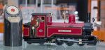
I've just received the swift sixteen kit for the railbus and I must say I am very impressed with the quality of the kit. I think Rob might use magic to produce such large, well formed castings in one piece! As I am building this one for someone else it is 32mm gauge. I aim to add extra detail as we progress to make it more like the bubble car at the North Norfolk.
I need to sort out a new photobucket and then I can add some pictures.
Swift Sixteen Railbus Build
-
Dr. Bond of the DVLR

- Retired Director

- Posts: 4485
- Joined: Tue Jun 09, 2009 9:43 pm
- Location: Suffolk
- Contact:
Swift Sixteen Railbus Build

The railway which people forgot
(to build)

-
Dr. Bond of the DVLR
- Retired Director
- Posts: 4485
- Joined: Tue Jun 09, 2009 9:43 pm
- Location: Suffolk
- Contact:
-
RylstonLight

- Trainee Fireman

- Posts: 209
- Joined: Fri Oct 26, 2012 3:10 pm
- Location: Pontefract West Yorkshire
Invest in the best end-cutters you can afford - the stainless steel wire is very tough. I bought a "reasonable pair" from Halfords and ruined them after the first lot of seats.Mr. Bond of the DVLR:110668 wrote:I am quite excited about getting started. I've drawn up a tool list, it seems that there are many odd sizes of drill required.
The railbus is so well designed you can assemble it on a dry-run and then push along a track without it falling apart. That's impressively stable.
Actually squeezing all the wiring into the underchassis is something of a challange though.
Andy S
Andy S. at the Rylston Light Railway

-
Chris Cairns
- Driver

- Posts: 2366
- Joined: Mon Oct 29, 2007 7:25 pm
- Location: Glasgow, Scotland
That is an interesting fact Brian.
I've just obtained 2 Short Coach's and the online instructions state to use a 1.7mm drill for the coupling hooks & brass wire grab rails. Just checked them with my recently obtained Lidl digital calliper and the brass wire is actually 1.54mm/0.061". So I guess this is nominally 1/16"/0.625" brass wire then?
Just as well I used my 1.5mm drill bit on the buffers and not a 1.7mm drill bit then!
Chris Cairns
Last edited by Chris Cairns on Sun May 10, 2015 11:13 am, edited 1 time in total.
-
RylstonLight
- Trainee Fireman
- Posts: 209
- Joined: Fri Oct 26, 2012 3:10 pm
- Location: Pontefract West Yorkshire
I have been assembling and re-assembling dry runs to determine the best wiring layout/runs (for lights as well as the motor). In doing this I have a slight concern about the permitted rotation of the powered bogie.
Has anyone had a minimum radius quoted to them. I have re-looked at the Swift Sixteen website and can't see one.
I have been aligning the powered bogie on a length of Peco SM32 settrack curve (IIRC 30inch radius), and it looks like there is little chance of it going around that. There appears a little space to ease the arcs cut out of the floor in the powered end, and that might gain a little extra rotation.
Is there anyone further on in the assembly process who knows the minimum radius without easement? Alternately anyone less far on might want to look at this before fixing the floor assemblies especially if they have tightish radii to negotiate. Best be aware that the position you solder your suppression capacitors to the motor terminal can foul the seats when in situ and reduce the potential rotation. Try to keep them to the midline of the motor-chassis axis.
I can provide pictures if people want.
Andy S
Andy S. at the Rylston Light Railway
-
RylstonLight
- Trainee Fireman
- Posts: 209
- Joined: Fri Oct 26, 2012 3:10 pm
- Location: Pontefract West Yorkshire
Well I decided to rush in where fools . . .
and picked up a half-round file. By much trial and error (and taking small amounts off) I eased the motor cut-out in the floor.
The top floor is the easement that allows 30inch radii to be negotiated; the lower floor is as moulded.

However the motor top just fouls the seats; and these need filing at a forty-five degree angle thus:

Of course anyone sensible will do this before painting the chairs and gluing them to the floor assembly!
Here is now the railbus (just clipped together not glued) negotiating a settrack curve:

I am aware that I have hijacked the thread a bit, but wished I knew then what I know now, and thought you might want to ease the cut-out before painting. I look forward to Mr Bond's narrative. Especially how you tackle the power/control of the motor, and fit it all in.
Andy S - largely answering his own earlier question!
and picked up a half-round file. By much trial and error (and taking small amounts off) I eased the motor cut-out in the floor.
The top floor is the easement that allows 30inch radii to be negotiated; the lower floor is as moulded.
However the motor top just fouls the seats; and these need filing at a forty-five degree angle thus:
Of course anyone sensible will do this before painting the chairs and gluing them to the floor assembly!
Here is now the railbus (just clipped together not glued) negotiating a settrack curve:
I am aware that I have hijacked the thread a bit, but wished I knew then what I know now, and thought you might want to ease the cut-out before painting. I look forward to Mr Bond's narrative. Especially how you tackle the power/control of the motor, and fit it all in.
Andy S - largely answering his own earlier question!
Andy S. at the Rylston Light Railway
-
swiftsixteen
- Cleaner

- Posts: 92
- Joined: Sat Jan 14, 2012 12:49 am
Guys, please take note of the drill sizes I give you. I give these sizes for a reason.
I have now added this statement into the Railbus instructions:-
CURVATURE NOTE
This model will negotiate a two foot radius curve, but the floor motor cutouts will need enlarging. The thick motor bogie plate already has the larger cutout to negotiate down to a two foot radius. The floors were cast with small cutouts for those that do not run on such tight radii.
DRILL SIZE NOTE
All drill sizes are given in mm. Some of these sizes are very specific. These drills are readily available from any model tool outlet or Ebay. Please also note, that holes are deliberately made a fraction over size to allow glue into the hole for bonding. A hole drilled to the exact size of the object going into it, allows for no glue penetration and cannot therefore be glued!
Last edited by swiftsixteen on Tue May 12, 2015 11:48 pm, edited 1 time in total.
-
RylstonLight
- Trainee Fireman
- Posts: 209
- Joined: Fri Oct 26, 2012 3:10 pm
- Location: Pontefract West Yorkshire
The Swift Sixteen instructions are very explicit and helpful. But I started my assembly before they appeared on the website. My own choice; I knew they were coming but I never could resist peeping at Christmas presents either!
At times he is very specific about where to file and where to pare down with the back of a scalpel blade. These instructions are also there for a reason.
I am assembling a pair (one non-powered to give the option of MU operation), and so tried different methods on each one.
I found three things specified very true: a really really good wire cutter; a new file, and paring down where specified (rather than filing) WILL save you time.
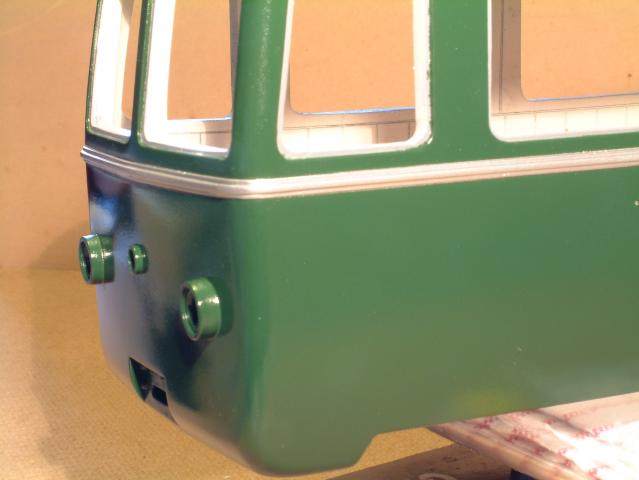
My biggest fear of cleaning up the moulding at the corners where they are well-exposed was groundless. It really didn't take long, just follow
the instructions.
Before:

After:
I am impressed with this kit and its instructions. The only (hair-splitting) fault so far is that the original instructions didn't draw attention to opening up the motor cut out. But the fact that you can assembly it dry and push it along track made me realise the need to do it.
Also first rate response - the instructions have been amended within less than 24h of the problem being mentioned.
At times he is very specific about where to file and where to pare down with the back of a scalpel blade. These instructions are also there for a reason.
I am assembling a pair (one non-powered to give the option of MU operation), and so tried different methods on each one.
I found three things specified very true: a really really good wire cutter; a new file, and paring down where specified (rather than filing) WILL save you time.
My biggest fear of cleaning up the moulding at the corners where they are well-exposed was groundless. It really didn't take long, just follow
the instructions.
Before:
After:
I am impressed with this kit and its instructions. The only (hair-splitting) fault so far is that the original instructions didn't draw attention to opening up the motor cut out. But the fact that you can assembly it dry and push it along track made me realise the need to do it.
Also first rate response - the instructions have been amended within less than 24h of the problem being mentioned.
Andy S. at the Rylston Light Railway
The difference between a 1.6mm drill and a 1/16th" drill is so small they are basically the same. Metric drills are slightly easier to obtain so go for the 1.6...
We have several of robs kits and we also find that 1.6mm drills are ideal as there is just enough glue space to be effective. Any smaller and you wouldn't get glue in and any bigger and the hook wont stay.
Hope this helps guys!
We have several of robs kits and we also find that 1.6mm drills are ideal as there is just enough glue space to be effective. Any smaller and you wouldn't get glue in and any bigger and the hook wont stay.
Hope this helps guys!
Who is online
Users browsing this forum: No registered users and 1 guest