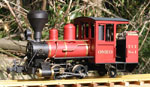

I had considered r/c, but I dislike the ergonomics of model aircraft and car radio transmitters. I do not get on with joysticks and r/c car controllers are downright weird for loco use. I had contemplated repackaging the bits of a transmitter into a more useable package, but it was low on the priority list.
Recently Tony Walsham at RCS here in Aust ( http://www.rcs-rc.com ) introduced a new range of handheld r/c transmitters that looked more like what I wanted, so I sent him an order for one of the new TX-3 transmitters, as well as a micro servo and a DSM2 receiver. The various other bits of electrickery came from the local Jaycar store.
These are the various bits before assembly into the loco. The transmitter fits neatly into a shirt pocket and I can use it one handed without looking at it. The battery pack was made up from four AAA size Eneloop batteries. These were chosen as they hold a charge for over a year, unlike ordinary NiMH batteries, which are lucky to last for a week. The yellow disc shaped component is a polyswitch, used to limit battery current to a very low level if anything goes wrong.

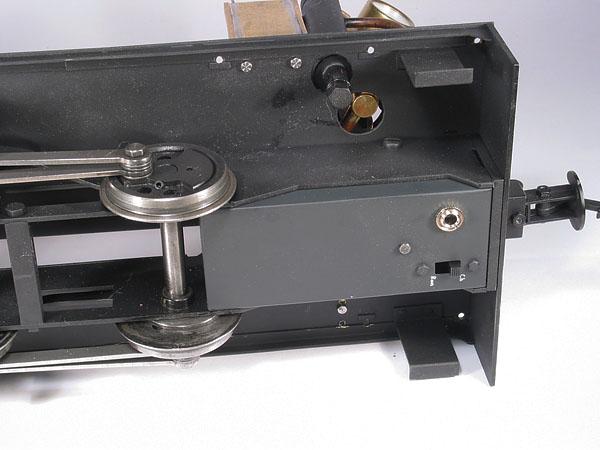
The first issue was where to put the batteries on the loco. A battery wagon wasn't going to happen and under the the cab roof was out as well. By using AAA cells it was just possible to fit the battery pack in a box under the cab floor which was more or less invisible from normal viewing heights.
This shows the battery box wired up with the power/charge changeover switch, polyswitch and charging socket fitted.

This shows the battery box fitted under the cab floor.
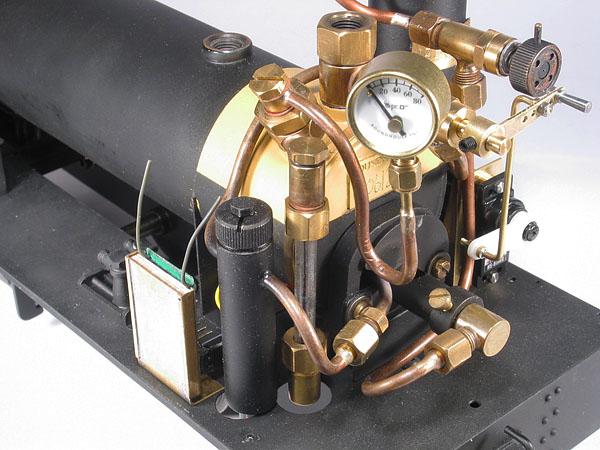
Next up was to fit the throttle servo. There isn't a lot of space in the cab, but I managed to fabricate a mount and squeeze it in, up against the cab side sheet, in front of the gas tank, as far from the boiler as it can get. A throttle handle and linkage was also fabricated and this is also visible. The throttle handle is new, but the body and spindle is the original manual throttle that came with the boiler. I'm hoping someone makes a black servo arm that will fit the micro servo, as the white one is very obvious in the cab door and it's made from acetal which doesn't take paint well. This shows the setup.

Last to be fitted was the receiver, which is tucked into the front corner of the cab and is fixed to a wooden plate to provide both electrical and heat insulation from the bodywork. This photo shows the bracket arrangement. The power and servo cables are tucked under the boiler and aren't visible once the cab is fitted.
This all took about a week to set up and function test on the bench.
Then it was time for a road test. The first mistake was to fit the bodywork before the test......
The transmitter worked well and I really like the control arrangement and feel.
Problems encountered were partly radio installation related, plus a couple of unrelated mechanical issues.
The loco had been bench tested on a rolling road, which provides a bit of rolling resistance and makes the loco under test work a bit. On the road it turned out the throttle wasn't closing completely and the loco couldn't be stopped on a downgrade. Full valve gear can always be put into mid gear, or even reverse if necessary, but slip eccentrics provide no braking and with just a wisp of steam going to the cylinders it just kept rolling.
The mechanical issues were a safety valve that decided it was now set to blow off at 20psi and a crankpin that decided this was a good time to come loose and drop out.
Back to the workshop...........
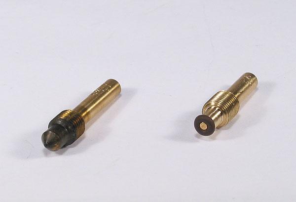
A new throttle spindle was turned up and fitted with an o-ring similar to the Roundhouse r/c throttle design, but with the finer thread of the manual throttle. I couldn't see any point in changing the thread pitch as the throttle already had plenty of travel. This shows the new spindle compared with the old one.
The safety valve was adjusted and tested a few times to ensure it was working properly and the crankpins were all checked.
A few more bench runs with no load on the wheels demonstrated that the new throttle spindle was working as intended and the loco stopped when the throttle was closed.
Time for another track test when the weather finally decided to co-operate....
I left the bodywork off and this time it all worked as intended. It stopped on downgrades and started on upgrades, ran smoothly in both directions and was easy to keep running at a more or less constant speed when it was running light engine.
Time for a load test. The first train was with a train of three bogie wagons and a 4 wheel van. This worked well. It was possible to stop and start both on up and down grades and maintain speed.
Then two more loaded bogie wagons were added to really test it. This time it required a lot more throttle to start the train and it would slip for half a wheel rev before getting enough traction to start the train on a grade. Stopping became interesting as the train weight kept it rolling on a downgrade for some distance.
All in all the conversion seems to have gone well. I'm happy with the transmitter controls and r/c has certainly tamed this loco when running on an undulating track. Just have to make that servo arm less obvious.......
Next step is probably to fit r/c to the little Argyle Baldwin, as that is also hard to control manually on an undulating track. It has full Stepho' valve gear fitted , so will get more advantage with the reverser servo driven as well. At least it will be able to stop a train on a downgrade.
Graeme
