Roundhouse Garratt

Discussion of Live Steam locomotives should be located here
User avatar
dewintondave
Trainee Driver
Trainee Driver
Posts: 697
Joined: Mon Mar 07, 2011 8:52 am
Location: New Zealand

Post by dewintondave » Tue Dec 31, 2013 2:50 am

ace:94520 wrote:That boiler looks promising, can I ask why you have the internal uptake tube? I thought the air came in the back of the burner and out the front into the smokebox?

I have to say, this project I am going to keep an eye on. :)
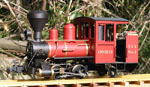
I didn't have room for a smoke box, I wanted the largest possible boiler to avoid water pumps. The uptake is reduced by a brass 1/2" K&S tube at the top. The exhaust doesn't go up the flue as the loco is a diesel :-) The loco has been running for a couple of years now.

Image

Best wishes,
Dave.

User avatar
dewintondave
Trainee Driver
Trainee Driver
Posts: 697
Joined: Mon Mar 07, 2011 8:52 am
Location: New Zealand

Post by dewintondave » Tue Dec 31, 2013 2:57 am

GTB:94560 wrote: Great minds think alike...... 8)
They sure do :-)
What burner design are you using? The cab photo looks like they are your own build.
They are full length standard type slotted-top burner tubes. I used the popular 5/16" K&S brass tubing.

Best wishes,
Dave.

User avatar
dewintondave
Trainee Driver
Trainee Driver
Posts: 697
Joined: Mon Mar 07, 2011 8:52 am
Location: New Zealand

Post by dewintondave » Tue Dec 31, 2013 3:16 am

ace:94617 wrote:So where does the exhaust from the cylinders go? I think I'd prefer to have a open smoke box and no uptake if it were mine.
The exhaust goes straight down behind the rear wheels.  This was a special set-up for an unusual model.  I think the boiler is efficient with the uptake, and is helped by being enclosed during running. The burners have proven to be quite quiet.

It would be much easier to have straight through tubes.  A 2 1/2" dia boiler with two 3/4" dia burner flues would be ideal for your project.

Here's a recent video showing the starting technique and the pleasing exhaust note.

http://www.youtube.com/watch?v=lxeLsfhgzyM

Best wishes,
Dave.

User avatar
GTB
Driver
Driver
Posts: 1721
Joined: Sat Mar 05, 2011 2:46 pm
Location: Australia

Post by GTB » Tue Dec 31, 2013 11:45 am

steamyjim:94594 wrote: Just out of interest, would the large Titch boiler be more suitable? I don't have my Titch drawings to hand, so I don't know if LBSC changed the diameter or length of the boiler when altering the design.

What about the Juliet boiler? That's a similar sized loco if I recall correctly
The small boiler is 2 1/2" dia. x 7" long. When the usual suspects moaned about the Tich boiler being too small, Curly drew up a larger 3" dia. x 7" long boiler. His own Tich was fitted with a belpaire variation of the small boiler. The drawing for the third boiler was in the ME article, but not in the book........

I did some more digging in the library.

The Juliet boiler is 3 1/2" dia. x 12 1/4" long. That works out about the right dia. for a VR G class as preserved at Puffing Billy, but the G was a 3' 6" design modified to run on 2' 6". It would need to be shortened as a G boiler is only 9 3/4" in 16mm scale.

I don't think there were any 2' gauge Garratts with boilers that large in dia. An NGG16 boiler scales out at about 3" dia. and about 9 1/2" long, so a lengthened large Tich boiler would do the job.

The Rob Roy boiler as originally drawn was 3 1/4" x 11 3/4". Fractionally smaller than a Juliet, assuming you can still get 3 1/4" tube. You certainly can't get it here in Oz.

Graeme
User avatar
GTB
Driver
Driver
Posts: 1721
Joined: Sat Mar 05, 2011 2:46 pm
Location: Australia

Post by GTB » Tue Dec 31, 2013 12:19 pm

dewintondave:94622 wrote: They are full length standard type slotted-top burner tubes.  I used the popular 5/16" K&S brass tubing.
Interesting, the first burner I built used 1/4" K&S tubing and it howled like a banshee. I somehow managed to get the dimensions just right for the gas flow to resonate.........

I rebuilt it with heavy wall tubing and three rows of holes like a Roundhouse burner and it's now nice and quiet. Too quiet, as I can't hear if it is still burning when there is any background noise.

There's still more black art than science in this loco building game.:roll:

Graeme

funandtrains

Post by funandtrains » Tue Dec 31, 2013 1:31 pm

A gas poker burner does not seem to be a very efficient way to heat a large diameter boiler as the surface area of the flue tube(s) is quite small compared to the water volume, this may explain why most gas boilers of 2.5 to 4 inch diameter sold for model boats use Cheddar type ceramic burners in flues with cross water tubes to maximise the surface area.

User avatar
dewintondave
Trainee Driver
Trainee Driver
Posts: 697
Joined: Mon Mar 07, 2011 8:52 am
Location: New Zealand

Post by dewintondave » Tue Dec 31, 2013 8:31 pm

funandtrains:94634 wrote:A gas poker burner does not seem to be a very efficient way to heat a large diameter boiler as the surface area of the flue tube(s) is quite small compared to the water volume, this may explain why most gas boilers of 2.5 to 4 inch diameter sold for model boats use Cheddar type ceramic burners in flues with cross water tubes to maximise the surface area.
We know that a single 3/4" flue with poker burner generates enough steam for a pair of Roundhouse cylinders. So two of those flues will produce enough steam for four cylinders. A 2 1/2" dia boiler with two 3/4" flues will have more heated area to water volume than a 2" dia boiler with a single 3/4" flue. But it's the heated area that's important.

Those marine boilers have huge flues as all the burner is at the backhead end, the water tubes will also help claw-back some of the lost water space.

Best wishes,
Dave.

jabsteam

Post by jabsteam » Tue Dec 31, 2013 8:38 pm

GTB:94470 wrote: As I've said before there is a reason why real Garratts have a short fat boiler. Looking at the drawings for K1, the first Garratt, the boiler scales out to 2 1/2" dia. by 8 1/4" long. That's big enough to fit two Roundhouse burners, so it would steam four cylinders easily with plenty of reserve and carry enough water to run for about half an hour like other Roundhouse models.

Regards,
Graeme
Graeme - You mentioned drawings of the K1, do you know if there are drawings available for the Ceylon H1? I understand Brian Wilson has built several models of the H1, so there must be drawings out there somewhere...

User avatar
GTB
Driver
Driver
Posts: 1721
Joined: Sat Mar 05, 2011 2:46 pm
Location: Australia

Post by GTB » Wed Jan 01, 2014 4:44 am

dewintondave:94653 wrote: But it's the heated area that's important.
What he said. ;)

I dusted off my thermodynamics when I tested the Roundhouse loco., out of interest. RH boilers have about 10% thermal efficiency, but the burner generates about 5MJ/hr flat strap, so has no trouble turning water into enough steam for their cylinders.

You might get the efficiency up a bit with a different design, but it would require a much more complex boiler, at a matching increased cost in time, or money.

Graeme

User avatar
GTB
Driver
Driver
Posts: 1721
Joined: Sat Mar 05, 2011 2:46 pm
Location: Australia

Post by GTB » Wed Jan 01, 2014 6:44 am

jabsteam:94654 wrote: Graeme - You mentioned drawings of the K1, do you know if there are drawings available for the Ceylon H1? I understand Brian Wilson has built several models of the H1, so there must be drawings out there somewhere...
Brian has built at least four. I've seen two green ones, a red one and a black one running over the last few years at the Great Southern Steamup. You'll find film of them on Youtube.

As far as I'm aware there are no drawings for building models of the H1 and Brian hasn't published anything on his models in AME.

A more or less complete set of drawings for the K class are in the Australian National Archives in Hobart and can be viewed online at high resolution.

http://www.naa.gov.au/collection/search/index.aspx

Search for 'Garratt' Compound Tank Engines and don't look at me, that's what the Tasmanian Railways called them.......


The only CGR H1 drawings available that I'm aware of are in the Beyer Peacock Archive at MOSI in Manchester. They have the general arrangement drawings (2 sheets) and two builders photos. online and they will sell you hires digital copies for 20 quid per drawing, or photo, but only lowres images are available online.

http://www.mosi.org.uk/collections/usin ... media.aspx

http://emu.msim.org.uk/htmlmn/collectio ... ype=images

Like most museum archives, the online search engine is crap. Try searching using Beyer Peacock & Co. Ltd in the collection name and Ceylon Government Railway in the object summary.

Graeme

jabsteam

Post by jabsteam » Wed Jan 01, 2014 5:09 pm

Thank you much Graeme, very helpful.

Jim Bruneau
Colorado Springs

Post Reply

Who is online

Users browsing this forum: No registered users and 14 guests