Helix rise and clearance

Do you have a problem? Here is the place to appeal for help
Post Reply
stevenfitch
Trainee Fireman
Trainee Fireman
Posts: 223
Joined: Thu Feb 19, 2015 7:46 pm
Location: Northumberland UK

Helix rise and clearance

Post by stevenfitch » Fri Aug 12, 2016 10:45 pm

Hi

Looking through various other posts the maximum gradient allowed should be 3% and clearance height should be enough for your tallest item (i need to go for 10").

So any ideas on the gradients involved in something like this and any ways to improve traction.

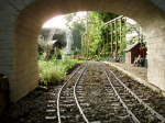
Taken from the following video
https://www.youtube.com/watch?v=R2ZMT3FgxOw

Image
Computer Controlled Garden Railway.
Previously N & OO Gauge Indoors.

stevenfitch
Trainee Fireman
Trainee Fireman
Posts: 223
Joined: Thu Feb 19, 2015 7:46 pm
Location: Northumberland UK

Post by stevenfitch » Fri Aug 12, 2016 10:49 pm

My current track plan for the area that this can fit into is the below.

Trains arrive from the rest of the railway on bottom track and depart on top track at top right of the plan.

Ignore the coloured sections, they are detection for automation.
I am limited to two sets of points in this area as there are only two pneumatic tubes available for control.

Image
Computer Controlled Garden Railway.
Previously N & OO Gauge Indoors.

User avatar
philipy
Moderator
Moderator
Posts: 6047
Joined: Sun Jan 30, 2011 3:00 pm
Location: South Northants

Post by philipy » Sat Aug 13, 2016 6:32 am

Stephen, I may be misunderstanding, but where you show what appears to be a diamond crossing will in fact be a flyover?
On that basis the answer to your gradient question surely comes out as: 10" clearance, plus track bed/bridge structure above, so call it 12" O/A. Max gradient of 1 in 30 gives 30 x 12" = 30ft minimum.
Philip

stevenfitch
Trainee Fireman
Trainee Fireman
Posts: 223
Joined: Thu Feb 19, 2015 7:46 pm
Location: Northumberland UK

Post by stevenfitch » Sat Aug 13, 2016 1:17 pm

Sorry no, that was the current plan using a diamond crossing, the idea is to alter that totally to include a helix etc. the only constraints are.

Maximum two sets of points (the green points count as one set).
The size of the area.
The entry and exit are at top right.

I have come up with the below

The YELLOW is the ramp up
The BLUE is the ramp down
All of the GREY is at the higher (10") level

(* need to take into consideration the height of track and supporting structures as well as rolling stock height from rail head).

Image
Computer Controlled Garden Railway.
Previously N & OO Gauge Indoors.

User avatar
philipy
Moderator
Moderator
Posts: 6047
Joined: Sun Jan 30, 2011 3:00 pm
Location: South Northants

Post by philipy » Sat Aug 13, 2016 3:09 pm

stevenfitch:119447 wrote:Sorry no, that was the current plan using a diamond crossing, the idea is to alter that totally to include a helix etc. the only constraints are.

Maximum two sets of points (the green points count as one set).
The size of the area.
The entry and exit are at top right.

I have come up with the below

The YELLOW is the ramp up
The BLUE is the ramp down
All of the GREY is at the higher (10") level

(* need to take into consideration the height of track and supporting structures as well as rolling stock height from rail head).

Image
I thought I must be misunderstanding!
So the basic gradient calculation is the same, give or take, and you need a minimum of 30ft run to get max 1:30 gradient. That means on your latest proposal you need a minimum of 30ft from the point at which the blue coloured line starts, from the grey line on the RHS, to the beginning of the blue RH curve on the LHS of the inner loop.
Only you know if the length of those two straights plus the circumference of the curve, will give you that 30ft minimum. The same thing applies to the yellow line of course but since that is the outside, if it works for the blue line the yellow is probably OK as well. However don't forget that the first( upper) section of the yellow line can't actually be part of the gradient because it needs the full clearance where it passes under the grey lines to the left of the grey spur.

Its your railway and you can do what you like, of course, but to me it looks as though you are building in massive complications just for the sake of it.
Philip

stevenfitch
Trainee Fireman
Trainee Fireman
Posts: 223
Joined: Thu Feb 19, 2015 7:46 pm
Location: Northumberland UK

Post by stevenfitch » Sat Aug 13, 2016 3:52 pm

The rest of it (see below) is all flat so this is to be the 'interesting bit' at the other end. This also allows me to have two loops (one at each end) connected by a double through main line between them.

The automation can take care of the complexity from an operating point and i think this would require building on breeze blocks etc to get the raised areas and gradients stable.

I like the general look of this https://www.youtube.com/watch?v=8mtW3eus_dA but appreciate that this part of mine will be / look a lot more compact.

Whole railway (current plan):

Image

New area plan with some grey raised areas and bridges added:

Image

Composite of the two:


Image
Computer Controlled Garden Railway.
Previously N & OO Gauge Indoors.

Post Reply

Who is online

Users browsing this forum: No registered users and 20 guests