Hi Greg.
To answer your questions.
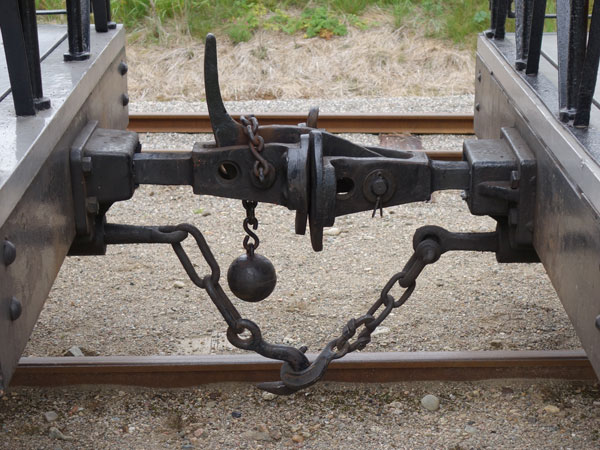
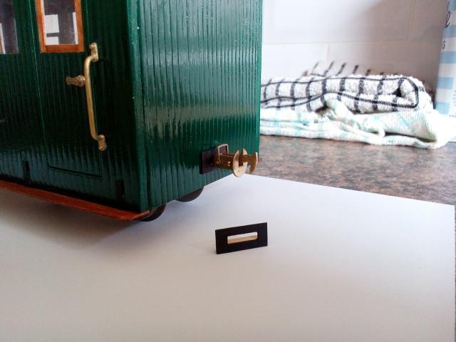
Above is a coupling on a coach with a drawing to make things clearer how I am doing it.
A - coupling head.
B - square portion on shift.
C - coach body with hole widened to the outside.
D - washer. Size to slide along round threaded portion of shaft but will not go onto square section of shaft. This washer is to stop the shaft sliding out of the coach body. This washer is not included in the kit.
E - spring on the round, threaded portion of shift.
F - nut to retain spring. I added a second as a locknut.
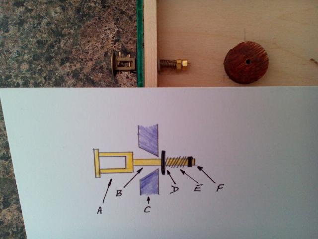
No bracket is included to attach the coupling to the underside of the coach.
I had a small hole drilled already for a buffer coupling so I squared this hole with a square needle file to accept the square shaft and then angled the hole width ways to allow the coupling to swing horizontally.
Here is a photo with the coupling in place with a rectangular plywood plate added to neaten up the look of the hole. I think it looks like a backing plate for the coupling. I might make some tougher plates in brass at a later date.
Sorry to ramble on but hope this helps to show how I fitted the couplings. There may be other methods and I might make modifications in the future.
David.
David T.