Construction of the MQR

Probably I only take pictures in the sun. Herefordshire, not known for tropical conditions! Actually, as I said way back at the start of this thread, I am telling this story as I get the time to write it up. We haven't caught up to the present yet so you are looking at some autumn sun here. I want to record the build more or less in order so that it makes sense through the stages of construction. Catching up though, so we will probably be in the rain soon.
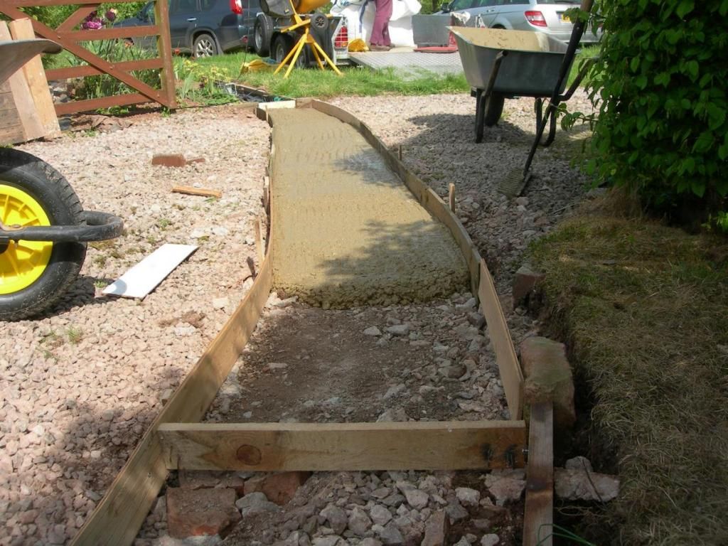
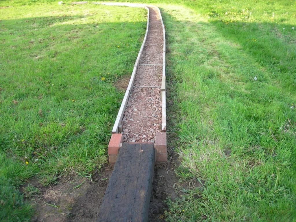
First layer of concrete. You can see the ends of the slab in this view where the plain track will start again
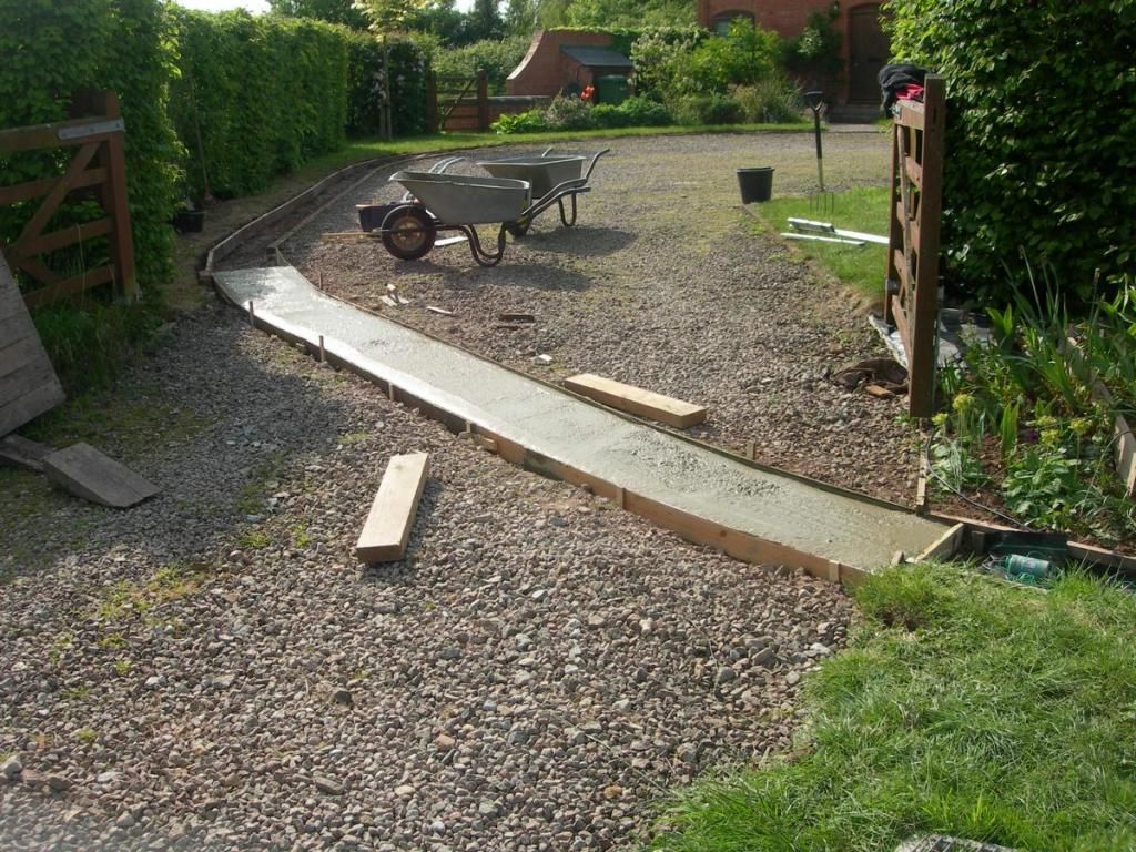
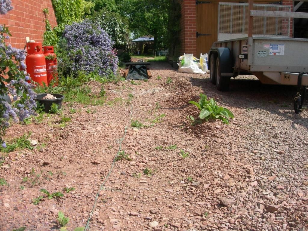
Now, filled up to the level where the track will be. You can just see the double (6m) length of track ready to be laid behind the wheelbarrows
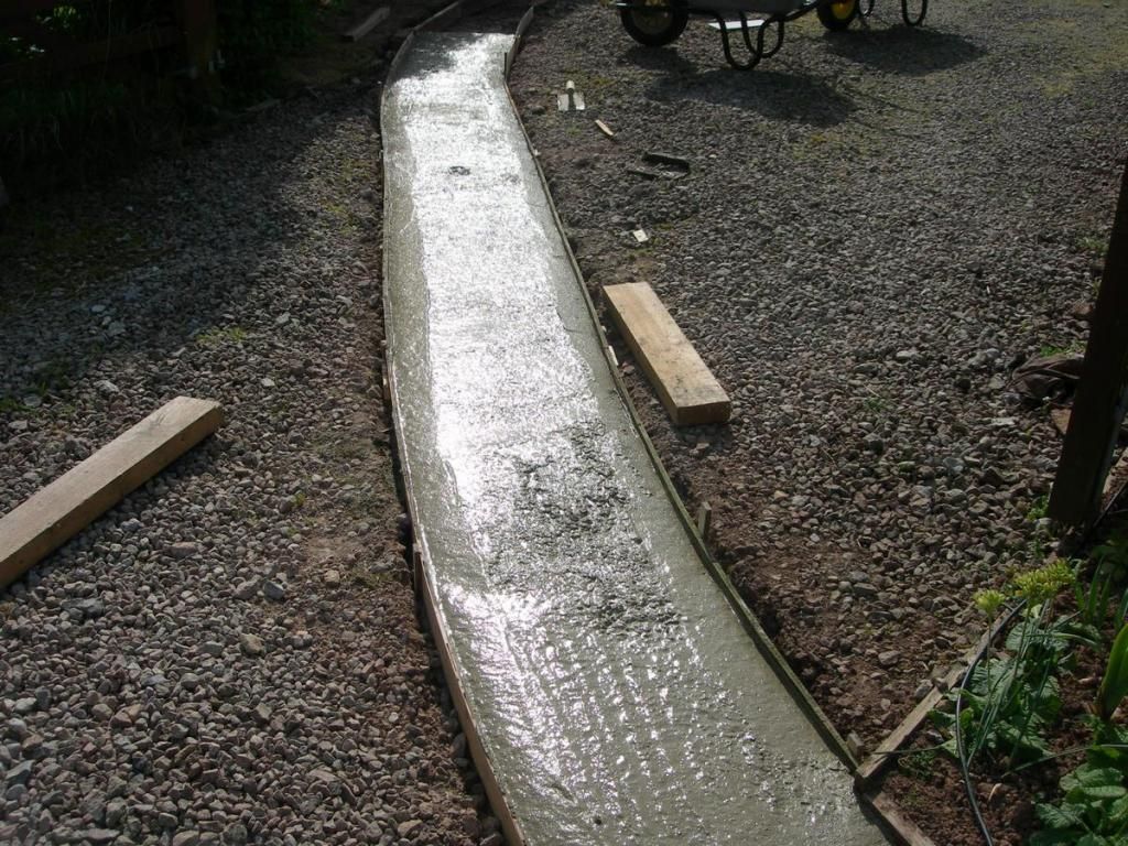
Ready for the track
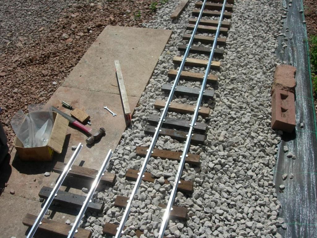
finally! some track laid. Here the special panel with the continuous check rails is just lying on the levelled bed of wet concrete. You can see the aluminium sleepers/spacers and the wooden sleeper fixed at the end where it will join the next panel of plain track.
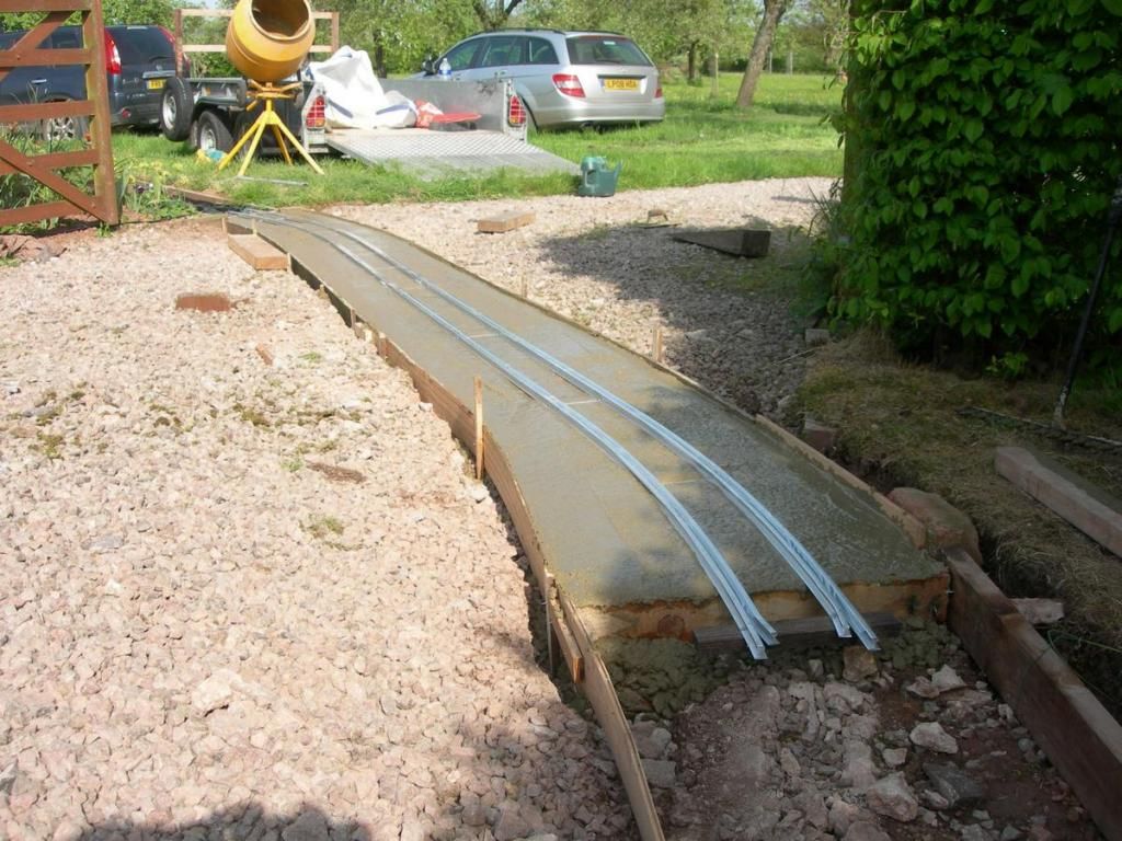
What doesn't show here is that the gap between running and check rail has been sealed by a strip of Cellotape right along the length. This is to stop concrete getting into the gap when the next layer is added to bring the level up to rail top height.
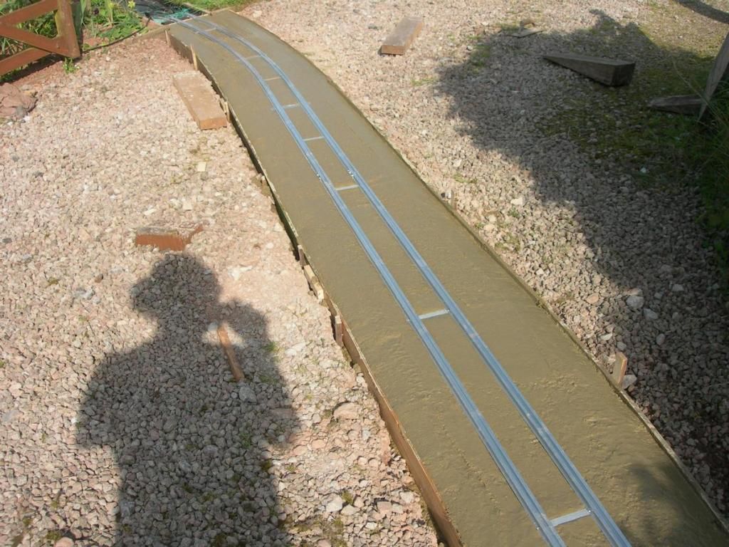
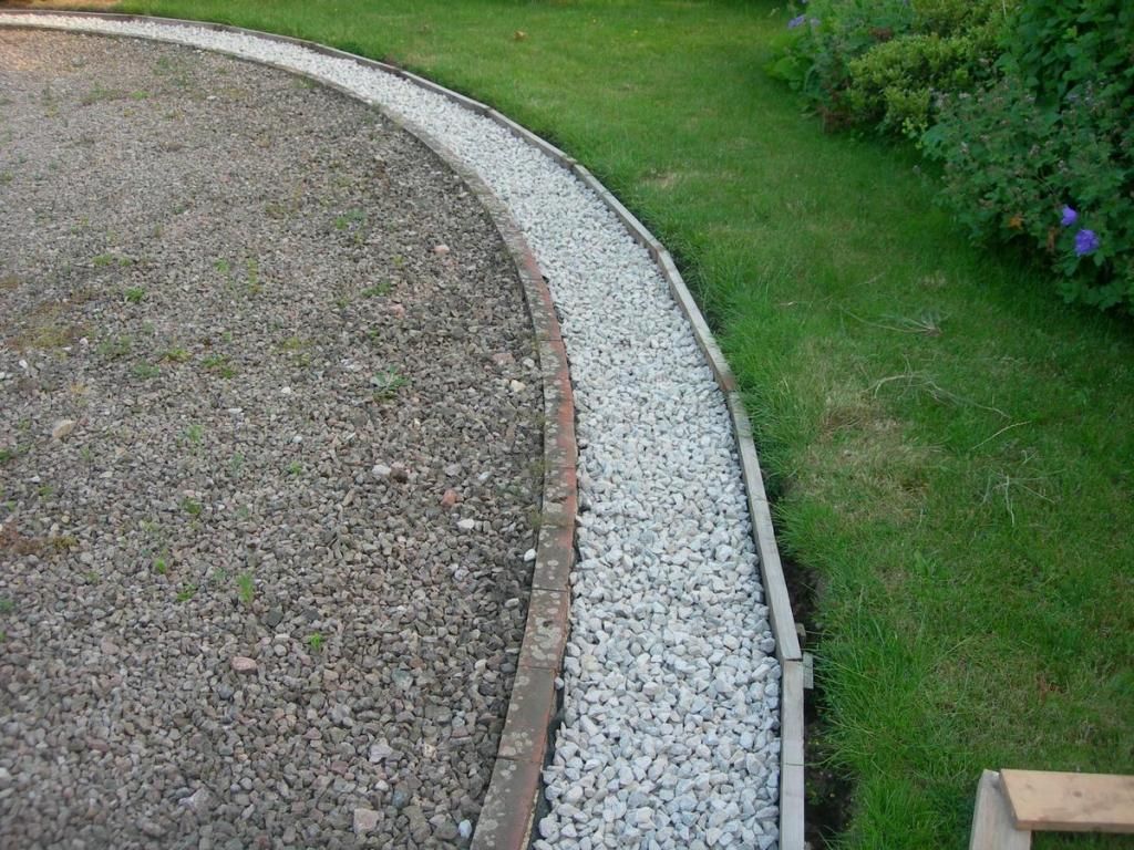
This shows the concrete up to rail top level with a slope to each side which will, I hope, keet the gracel out of hte gap between the rails. Some bits of concrete are sitting on top of the Cellotape in the foreground

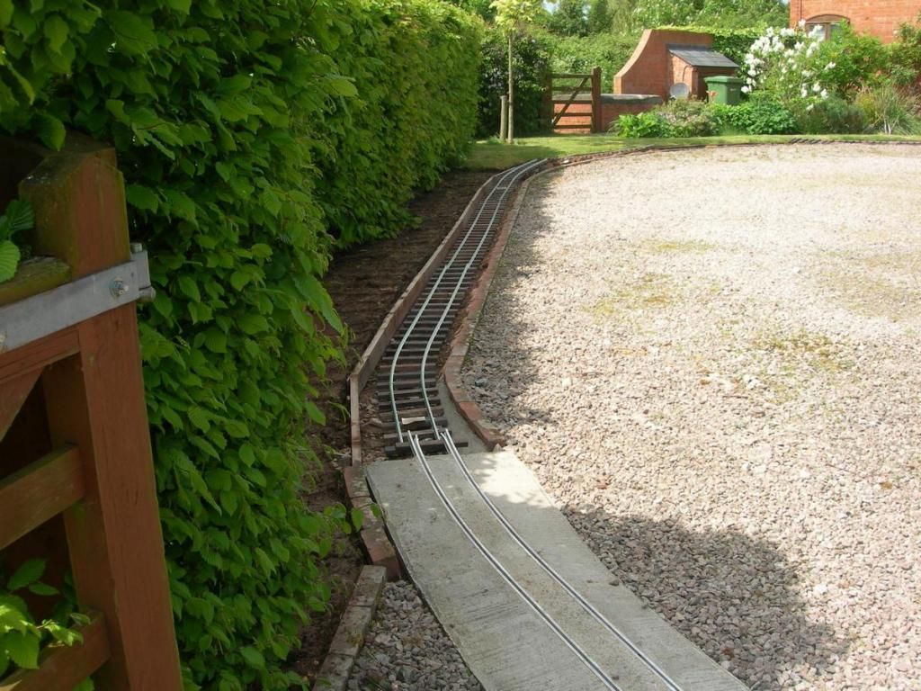
To me, this looks a bit like Penrhyn crossing on the FR with the oblique crossing, though in my case it goes through the gates, rather then them guarding the railway. Probably using too much imagination. This is one of the two key fixed points in the track laying. The other is the path crossing to the house which comes next.
Now, filled up to the level where the track will be. You can just see the double (6m) length of track ready to be laid behind the wheelbarrows
Ready for the track
finally! some track laid. Here the special panel with the continuous check rails is just lying on the levelled bed of wet concrete. You can see the aluminium sleepers/spacers and the wooden sleeper fixed at the end where it will join the next panel of plain track.
What doesn't show here is that the gap between running and check rail has been sealed by a strip of Cellotape right along the length. This is to stop concrete getting into the gap when the next layer is added to bring the level up to rail top height.
This shows the concrete up to rail top level with a slope to each side which will, I hope, keet the gracel out of hte gap between the rails. Some bits of concrete are sitting on top of the Cellotape in the foreground
To me, this looks a bit like Penrhyn crossing on the FR with the oblique crossing, though in my case it goes through the gates, rather then them guarding the railway. Probably using too much imagination. This is one of the two key fixed points in the track laying. The other is the path crossing to the house which comes next.

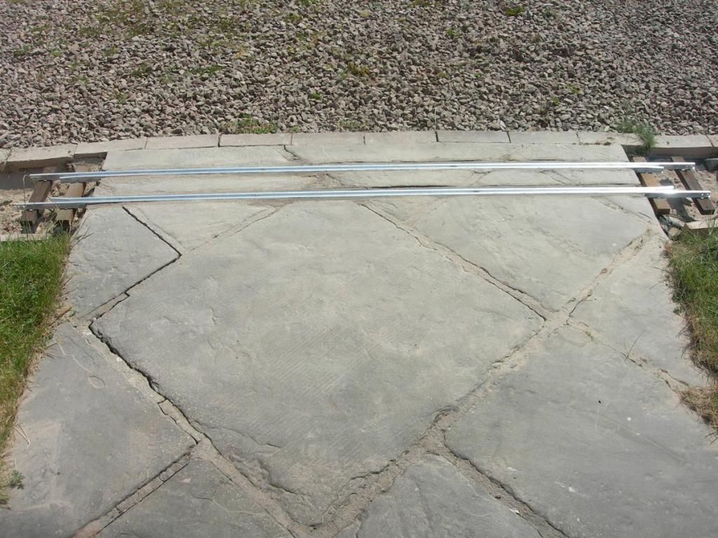
Trains just as soon as I get some track, and that is getting closer. If you turn around 180 degrees from the drive crossing, there is another obstacle to be crossed. The path from the drive to the house. This is laid with slabs which look quite thick. It was laid by the previous owner, so I don't know the details of construction. The slabs are quite good and I don't want to disturb them more than necessary
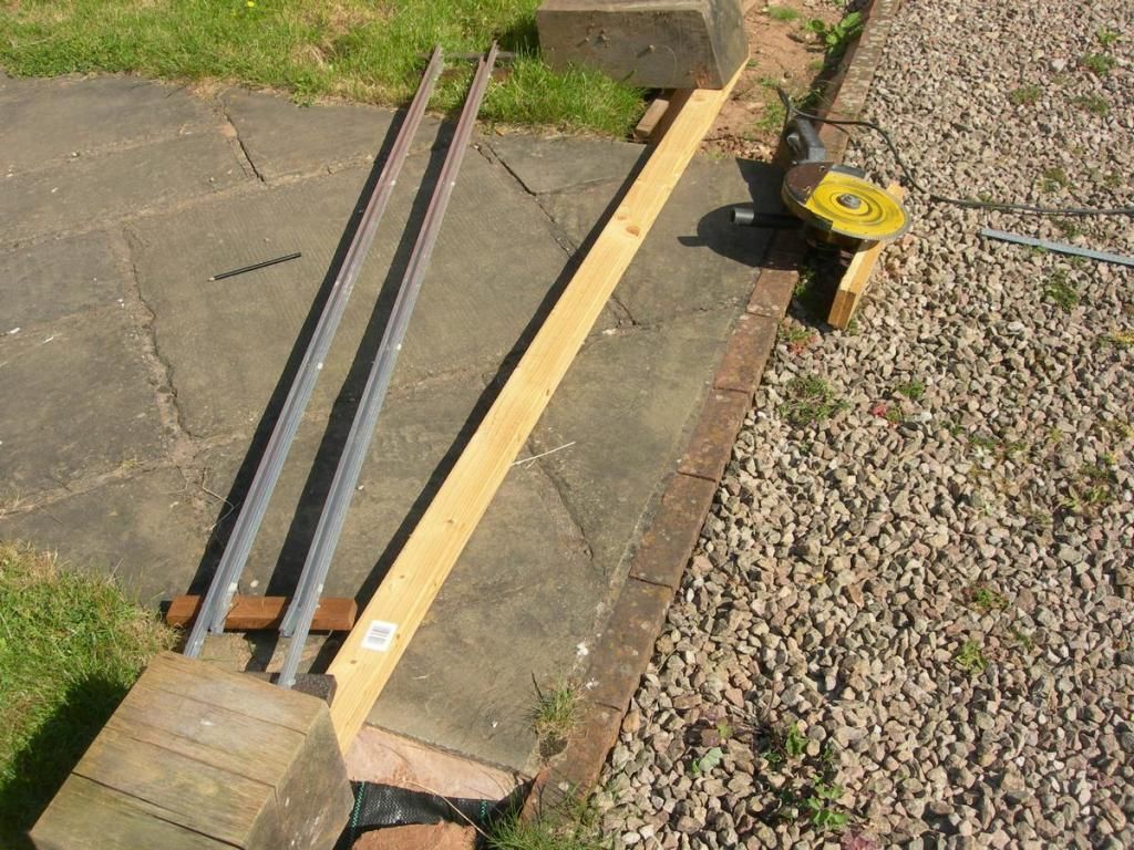
Here is another, shorter, special panel of track with continuous check rails. No intermediate sleepers this time, as I am planning to cut 2 slots across the slabs. The running and check rails clamped together by some clips made out of strips of aluminium are quite rigid, so I think gauge will be held ok. The yellow disk is a high quality cutting disc in a 10 inch angle grinder to which I have bolted a wooden foot which will run against the strip of wood to keep the cut straight.
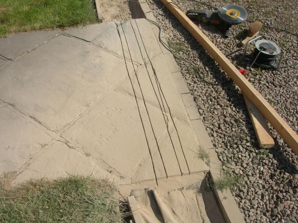
shows that is nearly worked! fortunately the mistake was into the slot I want to remove. What this doesn't show is the amazing cloud of dust created. You can see some of it settled in the trackbed at the bottom of the picture. Also, the yellow paint is gone from the disc!
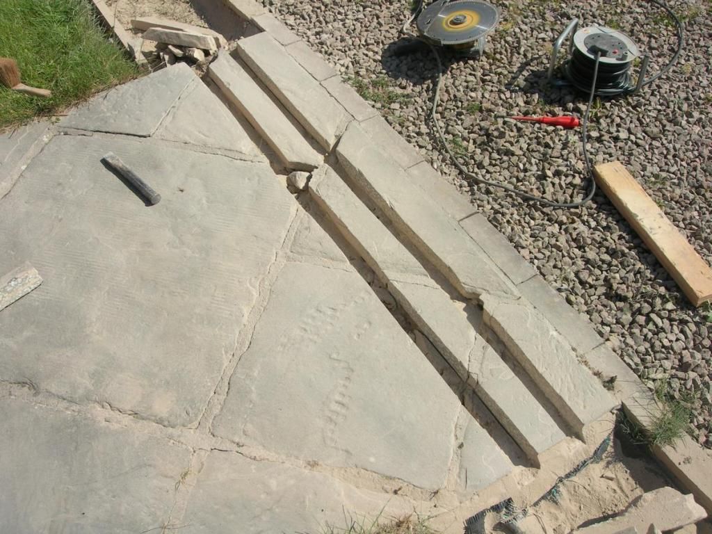
strips of slab removed, most off the slab between the rails stayed stuck where it should be.
tracks cemented into place. The result is quite neat and doesn't spoil the look of the path too much.
Here is another, shorter, special panel of track with continuous check rails. No intermediate sleepers this time, as I am planning to cut 2 slots across the slabs. The running and check rails clamped together by some clips made out of strips of aluminium are quite rigid, so I think gauge will be held ok. The yellow disk is a high quality cutting disc in a 10 inch angle grinder to which I have bolted a wooden foot which will run against the strip of wood to keep the cut straight.
shows that is nearly worked! fortunately the mistake was into the slot I want to remove. What this doesn't show is the amazing cloud of dust created. You can see some of it settled in the trackbed at the bottom of the picture. Also, the yellow paint is gone from the disc!
strips of slab removed, most off the slab between the rails stayed stuck where it should be.
tracks cemented into place. The result is quite neat and doesn't spoil the look of the path too much.
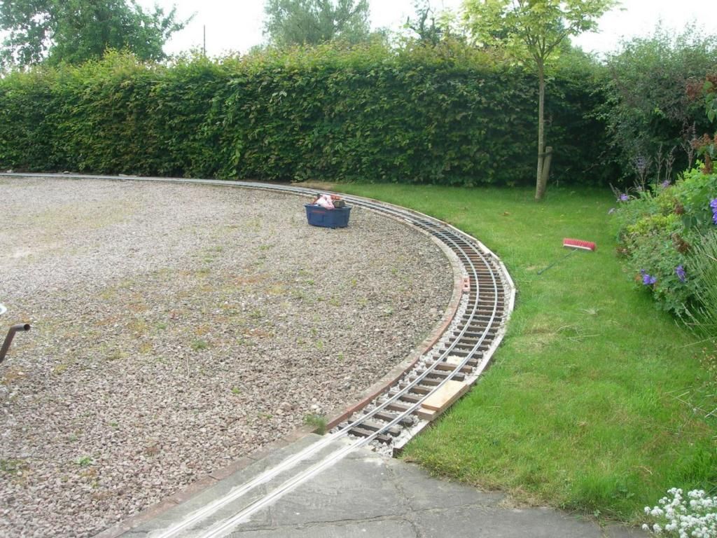
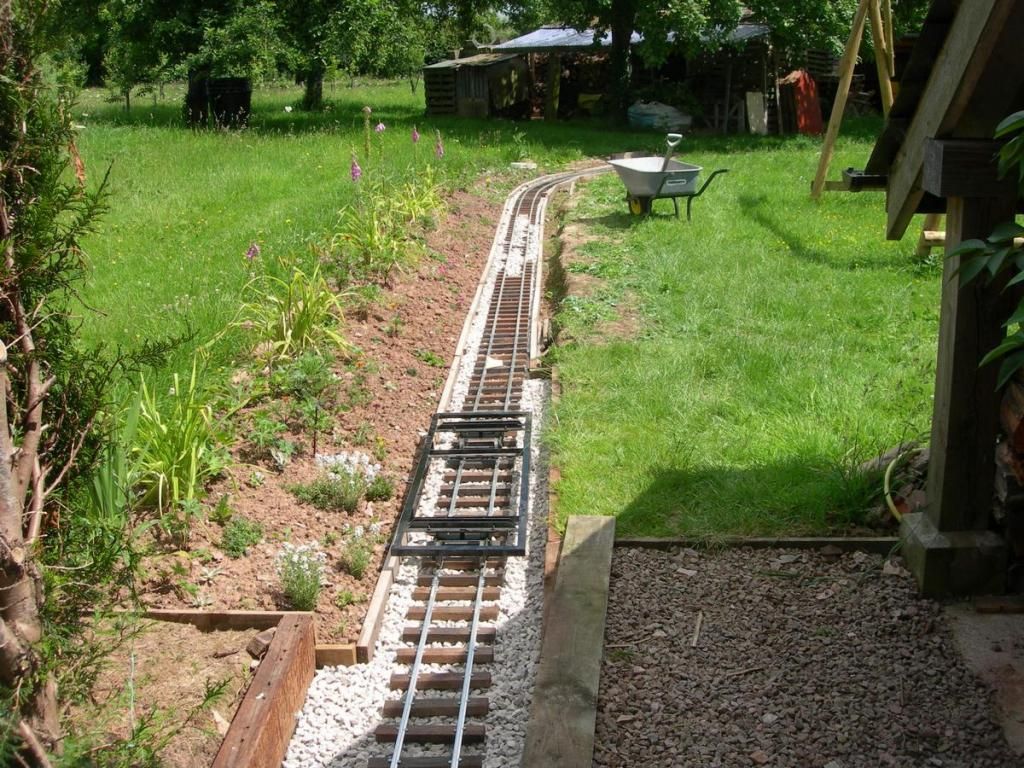
Now that both the fixed points on the circuit are in place, it is time to test the other panels for fit. Starting to look like a railway, except at this stage the weed barrier fabric and ballast are missing.
The panel in the foreground is one of those with a curved and a straight section. This is why each panel has a designated place. You can just see a bit of paper stapled to a sleeper near the camera, that has the position marked on it.
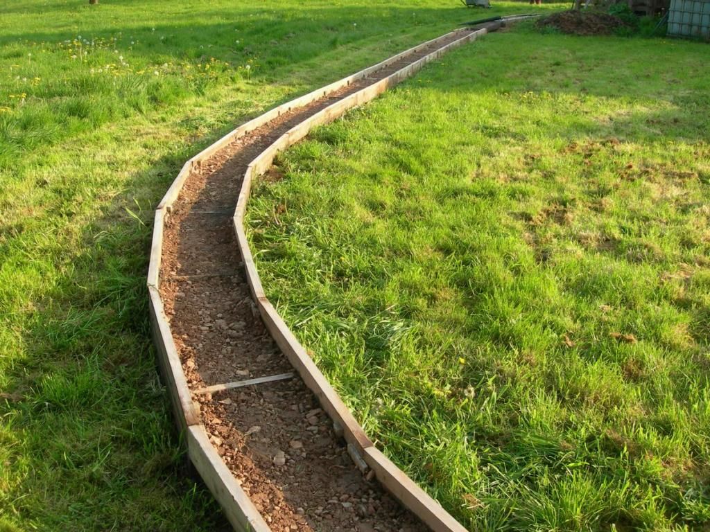
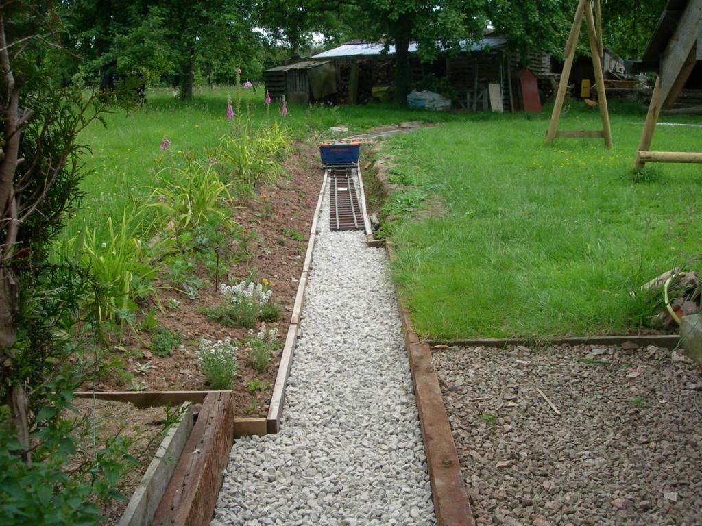
This shows the section with weed fabric at the top of the loop and the more open station area still waiting for it to be laid. Also the reason why it is needed. Weeds seem to grow well in the compacted sub-base!
Here is most of it laid in the station area. The real platform will be to the left of the temporary slabs, between the track and the house wall
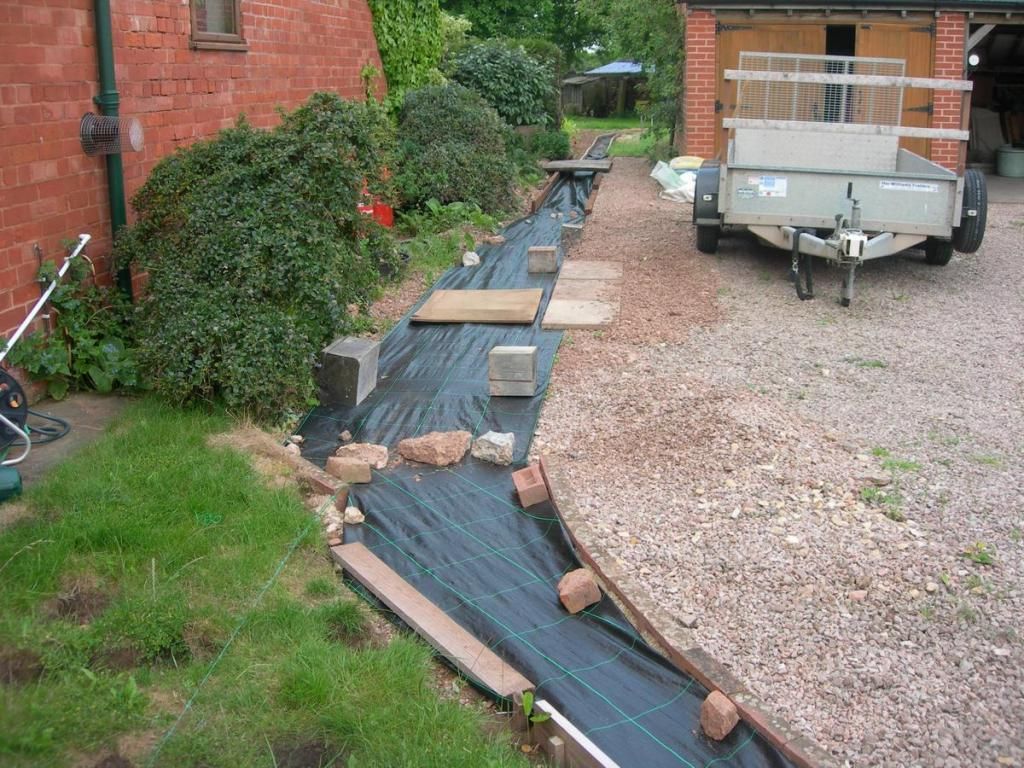
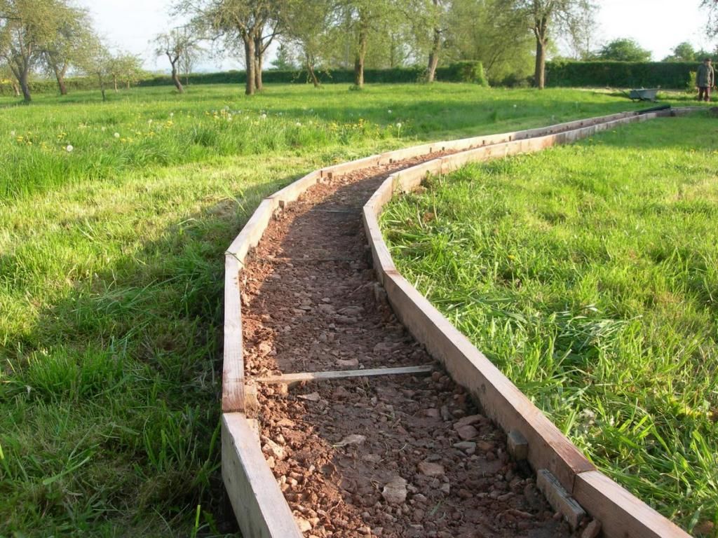
At the bottom side of the circuit the sub-base is in, just waiting for the weed barrier and ballast
Drivers eye view (if there was any track.)
The panel in the foreground is one of those with a curved and a straight section. This is why each panel has a designated place. You can just see a bit of paper stapled to a sleeper near the camera, that has the position marked on it.
This shows the section with weed fabric at the top of the loop and the more open station area still waiting for it to be laid. Also the reason why it is needed. Weeds seem to grow well in the compacted sub-base!
Here is most of it laid in the station area. The real platform will be to the left of the temporary slabs, between the track and the house wall
At the bottom side of the circuit the sub-base is in, just waiting for the weed barrier and ballast
Drivers eye view (if there was any track.)
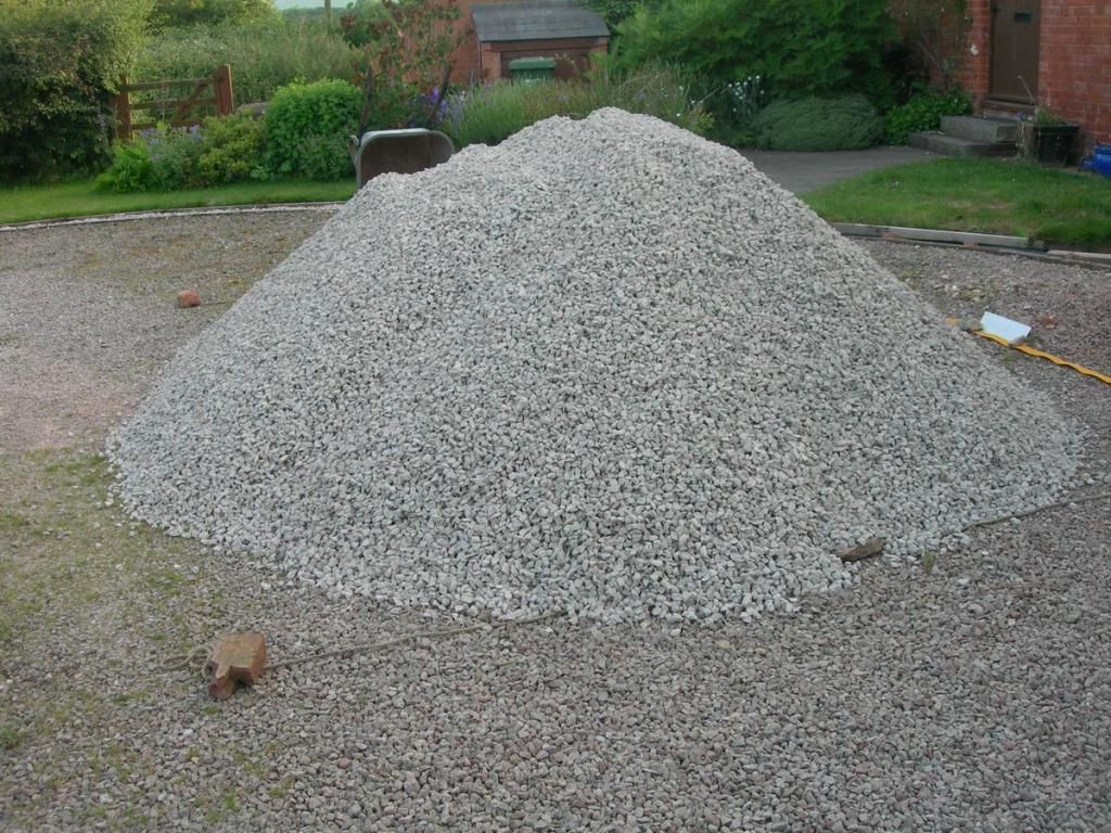
Yes, it is measured in tons now, and there is still a 10 ton heap of ballast on the drive. It is surprising how heavy everything is. On the plus side, it does feel as if I am building something permanent. This isn't going to get damaged by a passing cat (though I do have some concern about moles, of which we seem to have a lot in the orchard area)

Remember this? The 10 ton heap of ballast. It is where the story began at the top of this thread and its time has come.
Here is the trackbed with about 40mm of ballast laid. This is the amount that should be under the sleepers, allowing more to fill around the sleepers and pack them
Same thing looking the other way. It is surprising how much ballast is needed. a Wheelbarrow full, which is surprisingly heavy, only fills 2-3 m.
At last, some track that isn't buried in concrete. At this stage it is just laid on the ballast bed. I tried to level this as much as I could, but the angular ballast, that is essential to pack well and lock into place around the sleepers isn't easy to smooth out. It is actually well over scale (it is 14mm graded) but finer stuff would be moved too easily when cleaning leaves etc. off the track. As a result, something like a ballast plough would have to be close to 1:1 scale and not really feasible. Result was that I spent a lot of time poking around with a rake
A view toward the head of steel (aluminium) with a spirit level on hand to check cross levels. I am putting in a little super-elevation on the curves. 5 Inch gauge is really the smallest practical gauge for ground level passenger carrying and because of that stability is a bit of a concern. That is why I am doing everything I can to keep the centre of gravity where it needs to be. The level calculations on the bridge have come out OK. With the ballast in place the track runs onto the standard gauge sleeper that forms the bridge smoothly. It will be fixed through a couple of sleepers on the bridge.
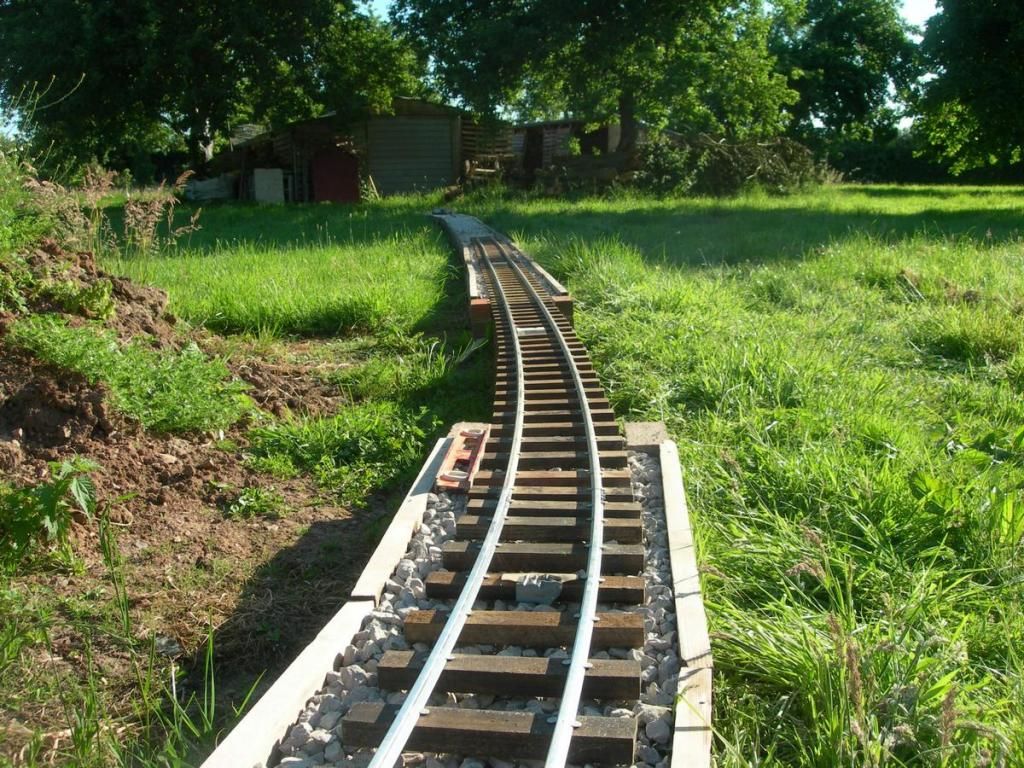
After months of digging and construction, this is the quick bit. The head of "steel" has moved up round the curve in the orchard onto the top straight. Construction train on the line, a plastic crate on an underframe!
Here is the trackbed with about 40mm of ballast laid. This is the amount that should be under the sleepers, allowing more to fill around the sleepers and pack them
Same thing looking the other way. It is surprising how much ballast is needed. a Wheelbarrow full, which is surprisingly heavy, only fills 2-3 m.
At last, some track that isn't buried in concrete. At this stage it is just laid on the ballast bed. I tried to level this as much as I could, but the angular ballast, that is essential to pack well and lock into place around the sleepers isn't easy to smooth out. It is actually well over scale (it is 14mm graded) but finer stuff would be moved too easily when cleaning leaves etc. off the track. As a result, something like a ballast plough would have to be close to 1:1 scale and not really feasible. Result was that I spent a lot of time poking around with a rake
A view toward the head of steel (aluminium) with a spirit level on hand to check cross levels. I am putting in a little super-elevation on the curves. 5 Inch gauge is really the smallest practical gauge for ground level passenger carrying and because of that stability is a bit of a concern. That is why I am doing everything I can to keep the centre of gravity where it needs to be. The level calculations on the bridge have come out OK. With the ballast in place the track runs onto the standard gauge sleeper that forms the bridge smoothly. It will be fixed through a couple of sleepers on the bridge.
After months of digging and construction, this is the quick bit. The head of "steel" has moved up round the curve in the orchard onto the top straight. Construction train on the line, a plastic crate on an underframe!
-
Dr. Bond of the DVLR

- Retired Director

- Posts: 4485
- Joined: Tue Jun 09, 2009 9:43 pm
- Location: Suffolk
- Contact:

Yes there has been an HPV trial. Fortunately because the camera was in my pocket it was not recorded! Gravity trains are successful too, coming to rest as expected at the low point just past the level crossing over the drive. At this stage the track is a bit uneven. Anyone got a 5 inch gauge tamper/liner?
-
robyholmes
- Cleaner

- Posts: 69
- Joined: Mon Mar 09, 2015 5:22 pm
- Contact:

Thanks everyone for the encouraging comments. It's good to know that you are enjoying watching the line develop.
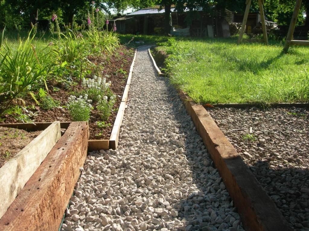
Here is the summit straight. The high point of the line is just in the foreground of this picture, where it enters the cutting alongside the path. The gradient is quite small where the chassis of the enclosed coach is sitting. any further back and it would roll away down the grade. The ballast to fill between the sleepers is visible further back
This is the place where the station platform will be. Tracklaying tools scattered about. Yes, you do need a hammer! It is used to tap on the end of the protruding rail on a panel to get the joints to line up evenly.
The bit I have been looking forward to laying - the turnout. I think it looks OK, though there is a bit more digging of turf to do to make the trackbed for the siding.
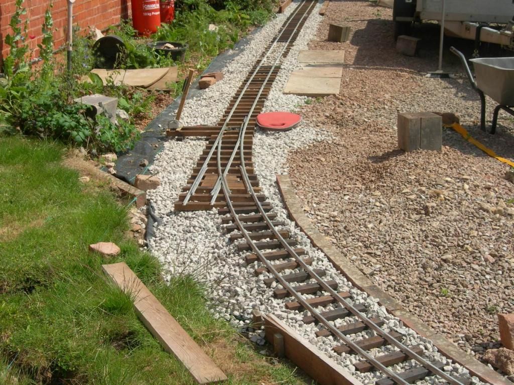
This is the result. The open area is meant for preparation of locomotives. One day there may be a turntable here.
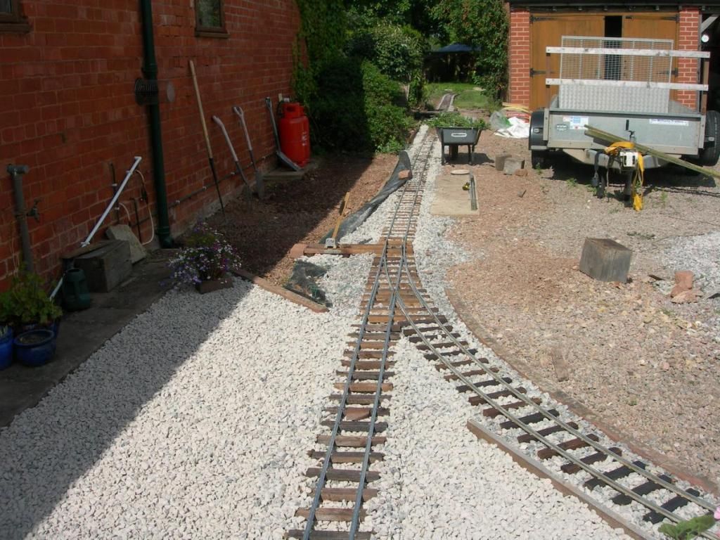
The area against the house wall in front of the gas bottles will be the station platform. I plan to built a railway looking shed/cover for the bottles. In future they may even get delivered by rail. They are heavy enough to make this an attractive idea even if it is only from the back of the car in the drive.
Getting close to the time for trains at last. It is tempting to rush this, but really I need to get the levels packed correctly and not risk kinking the relatively soft alloy rail. Looking forward to it though!
Here is the summit straight. The high point of the line is just in the foreground of this picture, where it enters the cutting alongside the path. The gradient is quite small where the chassis of the enclosed coach is sitting. any further back and it would roll away down the grade. The ballast to fill between the sleepers is visible further back
This is the place where the station platform will be. Tracklaying tools scattered about. Yes, you do need a hammer! It is used to tap on the end of the protruding rail on a panel to get the joints to line up evenly.
The bit I have been looking forward to laying - the turnout. I think it looks OK, though there is a bit more digging of turf to do to make the trackbed for the siding.
This is the result. The open area is meant for preparation of locomotives. One day there may be a turntable here.
The area against the house wall in front of the gas bottles will be the station platform. I plan to built a railway looking shed/cover for the bottles. In future they may even get delivered by rail. They are heavy enough to make this an attractive idea even if it is only from the back of the car in the drive.
Getting close to the time for trains at last. It is tempting to rush this, but really I need to get the levels packed correctly and not risk kinking the relatively soft alloy rail. Looking forward to it though!

It did go quicker than I was expecting. Each panel of track is 3m long and rigid. I have in effect made my own set-track, so it fitted together quite easily and 3m per section means you move forward quite fast. Each panel also weighs several kilos and stays pretty much where you put it, unlike trying to lay flexi (springy) track in smaller scales. Also, the ballast is working like on the prototype and is holding the track in place, rather than being a scenic addition later. In fact, the only places where the track is fixed by anything other than the ballast is at the crossings and on the bridge
Who is online
Users browsing this forum: No registered users and 2 guests