Rich,
In larger scale construction the rails are steel of course. Steel and concrete have equal co-efficients of thermal expansion so there is no differential movement. As the rails are encased in concrete and a large part of their surface area no longer exposed to direct sunlight, they tend not to expand (or contract) that much anyway. Certainly there is insufficient movement to warrant any concerns over expansion gaps or plate lubrication. In fact lubricating the plates is a positive disadvantage as it prevents the concrete bonding to the steel and allows the rails to move in the concrete in exactly the worst possible place - at the joint where the mechanics of the joint are already inclined to create movement. When a joint fails like this the action is as you suggest - break it out, reassemble the joint and recast a patch repair to the slab. All a darned sight more difficult to do than it is to say! Broken rail ends requiring a piece of rail cutting in are a particular delight!
I've laid a good deal of track in concrete in industrial situations and we NEVER lubricated the plates. There were three main methods of setting up the flangeways.
1. The best is without doubt the system you have used - a continuous check rail on both sides. There used to be a bullhead check chair (known as a 'glut' chair, specifically designed for the job. They were rare and very expensive if you wanted new ones cast so we used to use standard check chairs and drop the screws in loose before concreting. The alternative to this was to use check blocks bolted between the rails, often using the threaded tie bars that also held gauge. All a bit of a faff to set up but very durable and the easiest way of achieving gauge widening and the associated widened flangeway clearance and the easiest construction method using bullhead rail.
2. Some clients specified 'bulb flat' steel as a protective edge to the flangeway. This is flat plate with a thickened top edge to strengthen the exposed corner. We usually set this with check blocks between the rail and the flat plate, again often bolted through the threaded gauge ties bars. This was more common with FB track as fitting a FB check to a FB runner is far more involved because of the foot width. (When they are the same section the foot of the check needs to be planed down to achieve the flangeway gap).
3. The 'cheap and cheerful' method was to use tying wire to tie 2"x 2" timber to the gauge face of the running rail and then cast the concrete around it. Using mould oil generally released it ok but one Christmas we did a job this way under an opencast mine loading bunker. It froze hard that year and try as we might (with bars and hammers) we couldn't release it before the first train. I took a gamble and used the train to do the job - it worked!
Having dug the hole for the track slab and set up some shuttering (usually road pans used for highway slabs) we laid sub base (if required and then positioned bricks strategically to support the first layer of re-inforcing mesh. another set of bricks and the second layer of mesh went on top. The rail then went in the hole, again supported on concrete blocks or brick, finally we got the checking arrangements assembled. We used to set the gauge using threaded tie bars at about 2m intervals. these were nutted up on either side of both rails to set the gauge. All this could be pretty precarious! Sometimes the second layer of mesh would be laid at rail foot level, resting on the foot in the four foot and outside edges. Then it was concrete time, suitably vibrated and floated off.
All good stuff, the best aspects of which you seem to have incorporated into your construction.
Keep the updates coming, they are fascinating!
Andrew
Construction of the MQR
-
Soar Valley Light

- Driver

- Posts: 1451
- Joined: Sun Dec 08, 2013 5:18 pm
- Location: North West Leicestershire

Andrew,
This is really interesting stuff, thanks for explaining the reality of laying this kind of track. I will certainly dispense with the lubrication and make sure that the concrete is packed well around the joint in the rail. Fortunately there is only one as the rail comes in 3m lengths and the diagonal crossing of the drive is about 5.5m. Of course aluminium expands much more, so I will hope that your comment about less rail exposed to the sun (or ice) holds good for me.
I think my method is not too far from what you describe in your first point using continuous check rails. I will have both FB runner and check, so the flangeway will be a bit wide. I suspect it needs to be though, as clearances etc. do not always scale down 1:1. I have kept the foot of the two rails touching though. Where I have the aluminium plate sleeper. the rails are held with plated screws through the foot of the rail. The whole lot will be encased in concrete.
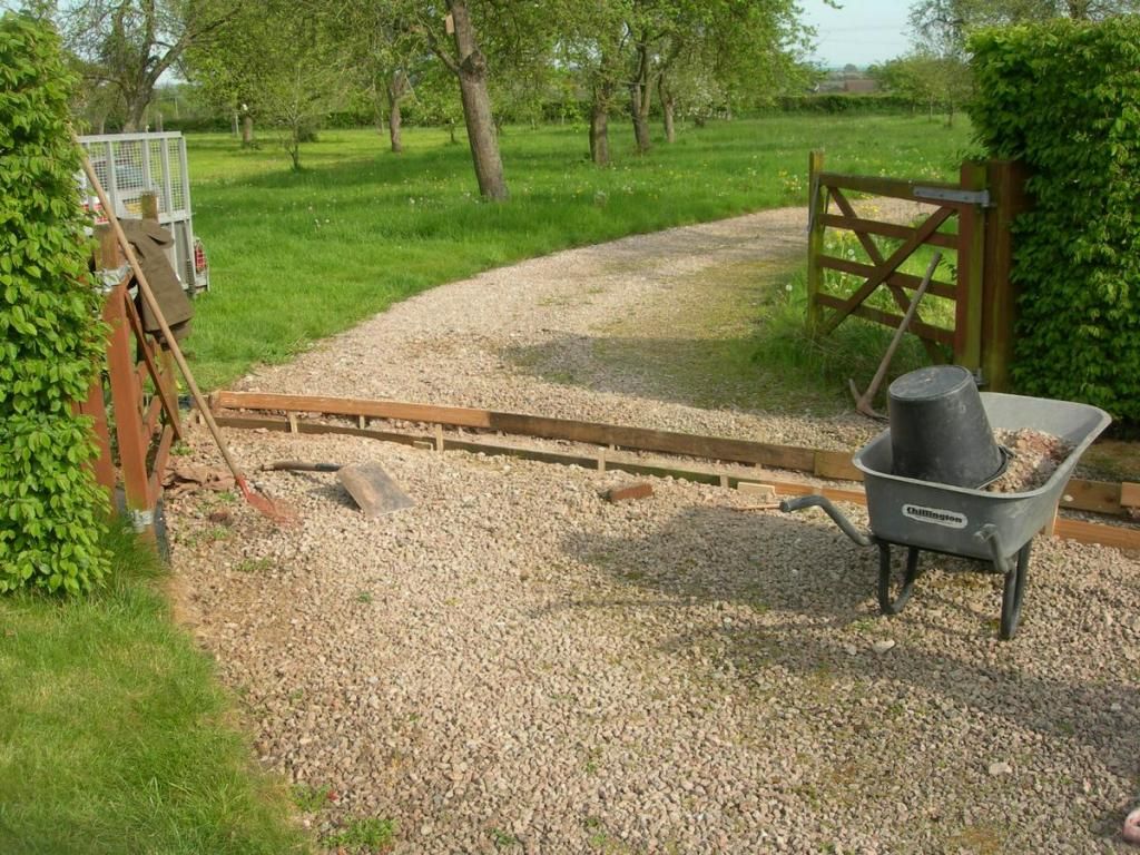
This is what I the line of the crossing will look like
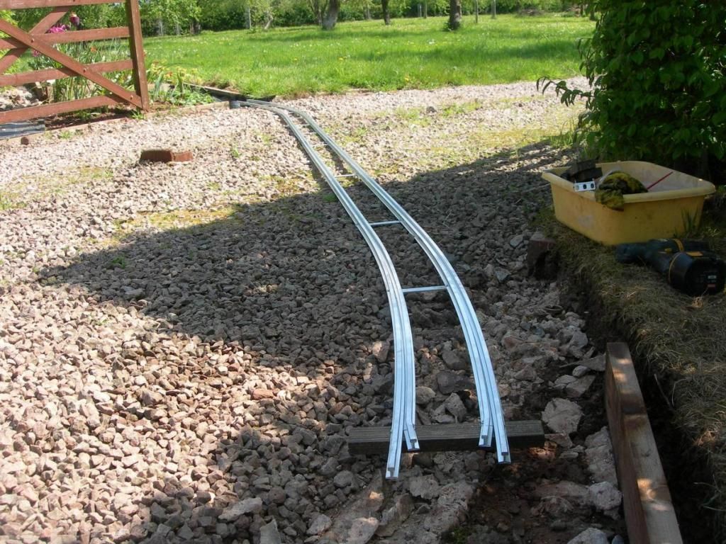
The line crossed diagonally through the double gates which could (if we ever closed them) shut off the house area from the drive through the orchard. However, the effect is like level crossing gates. I'm sure children will love opening and closing them for the trains. You can see that the brick edging of the existing grave drive had to be removed for the track to cross. The original construction was in some sort of super concrete that was very hard to break! the edging will be reinstated somehow to help the railway blend in.
This is really interesting stuff, thanks for explaining the reality of laying this kind of track. I will certainly dispense with the lubrication and make sure that the concrete is packed well around the joint in the rail. Fortunately there is only one as the rail comes in 3m lengths and the diagonal crossing of the drive is about 5.5m. Of course aluminium expands much more, so I will hope that your comment about less rail exposed to the sun (or ice) holds good for me.
I think my method is not too far from what you describe in your first point using continuous check rails. I will have both FB runner and check, so the flangeway will be a bit wide. I suspect it needs to be though, as clearances etc. do not always scale down 1:1. I have kept the foot of the two rails touching though. Where I have the aluminium plate sleeper. the rails are held with plated screws through the foot of the rail. The whole lot will be encased in concrete.
This is what I the line of the crossing will look like
The line crossed diagonally through the double gates which could (if we ever closed them) shut off the house area from the drive through the orchard. However, the effect is like level crossing gates. I'm sure children will love opening and closing them for the trains. You can see that the brick edging of the existing grave drive had to be removed for the track to cross. The original construction was in some sort of super concrete that was very hard to break! the edging will be reinstated somehow to help the railway blend in.
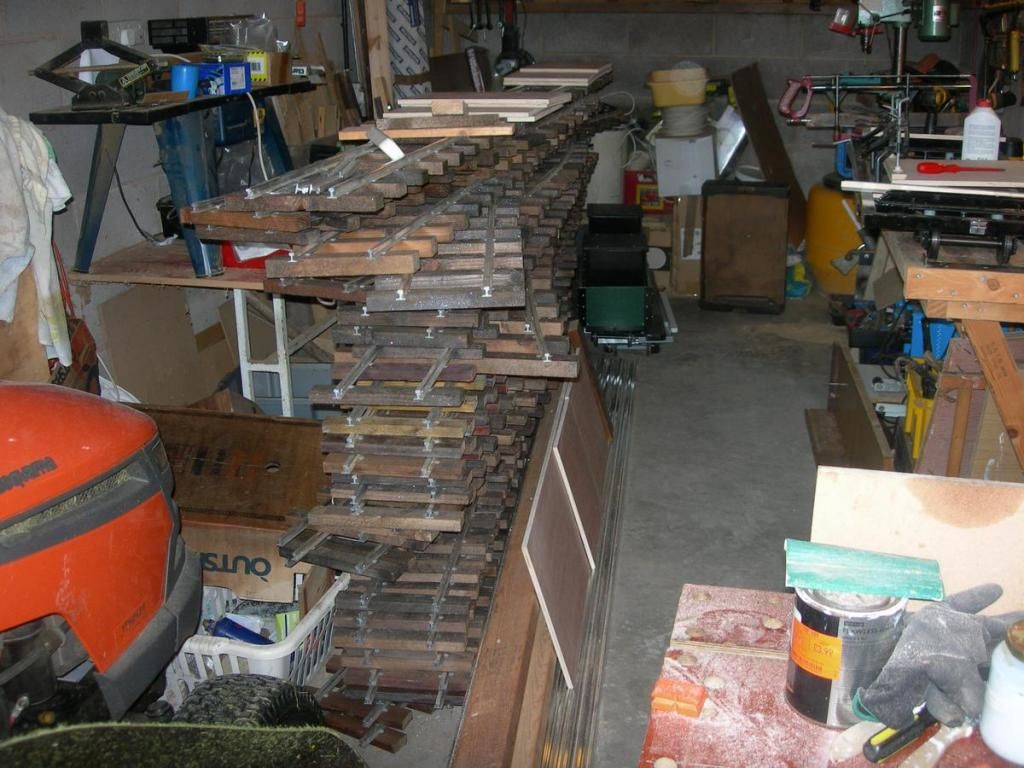
Meanwhile, the amount of track prepared is increasing.
Looking forward to being able to lay this and clear the garage a bit.
There is a mixture of straight and curved sections in the stack, Actually, each has a planned position on the line, as curves vary in radius, and some panels start or end straight and curve for the rest. I hope my measuring has been accurate or there will be a lot of "fettling" needed. I better get a big hammer ready.
-
Soar Valley Light
- Driver
- Posts: 1451
- Joined: Sun Dec 08, 2013 5:18 pm
- Location: North West Leicestershire
Hello Rich,
That's a very workmanlike job. I think your checking arrangement is spot on, the only reason it's kept so tight in standard gauge is to minimise the flangeway gap which is a tripping hazard and into which things can get wedged (resulting in de-railment in all likelihood!)
I'm really looking forward to seeing the finished crossing. In fact the whole railway is looking very good. The difficulties of laying small gauge railways should never be underestimated. I've laid track in gauges from 15" to 62'-6" (crane track!) and by far the most difficult and challenging was the 15" gauge!
All the best,
Andrew
"Smith! Why do you only come to work four days a week?
"'cause I can't manage on three gaffer!"
"'cause I can't manage on three gaffer!"

On modern prototype crossings, the area immediately adjacent to the running rail is a form of very hard rubber to make maintenance easier, might I suggest laying concrete to within inches of your rails but then using a fillet of ready to lay tarmac, which is easily available in DIY places. This will be much easier to dig out and repair when maintenance is required, bearing in mind alloy rail can wear away quite easily, especially on curves. The tarmac will look neat and be much more workable than concrete. Looks great so far by the way!
Interesting idea, tarmac. Not thought of that. That's what is great about a forum like this, plenty of ideas. I've only tried the DIY stuff once, and on that occasion the only thing it seemed to stick to was me. I'll definitely need practice before I would attempt to use it on detailed work.
The wear on the rails is something I thought about before I started. In many ways I would prefer steel, but it is quite a lot more expensive and harder to work for things like the turnout construction. In reality, this line isn't going to see much running so I'm hoping wear won't be too much of a problem. It is really for occasional sunny summer weekends (and we all know how few there are of them!). I mentioned earlier in the thread that I just like to look of the railway formation. Most of the time there won't be any trains. It is nice to drive over a level crossing on the way home though!
The wear on the rails is something I thought about before I started. In many ways I would prefer steel, but it is quite a lot more expensive and harder to work for things like the turnout construction. In reality, this line isn't going to see much running so I'm hoping wear won't be too much of a problem. It is really for occasional sunny summer weekends (and we all know how few there are of them!). I mentioned earlier in the thread that I just like to look of the railway formation. Most of the time there won't be any trains. It is nice to drive over a level crossing on the way home though!
Meanwhile, the paint-shop has made progress and we now have a more presentable carriage. It still needs some touching up where masking didn't work quite right. You can see the idea though.
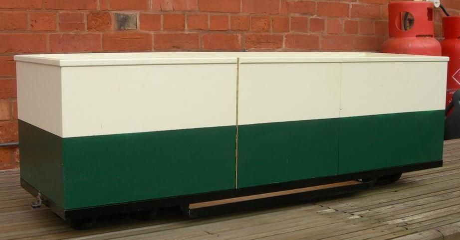
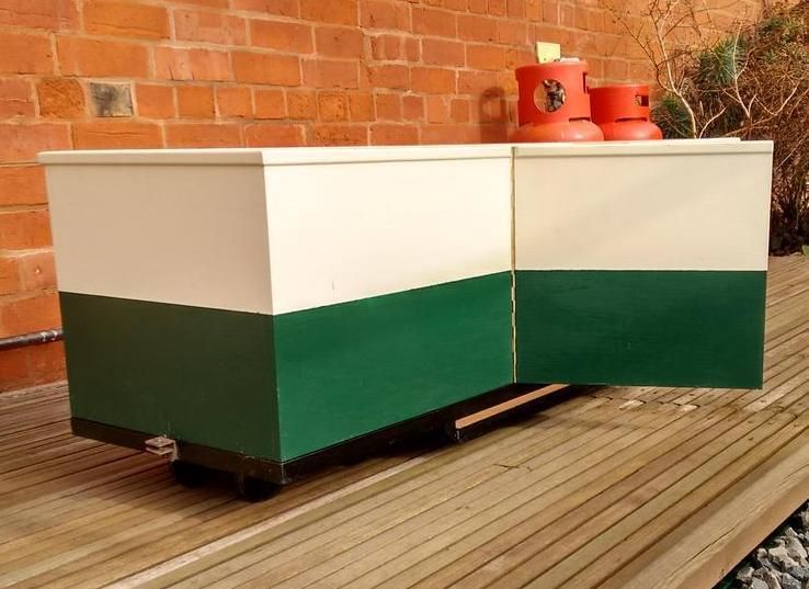
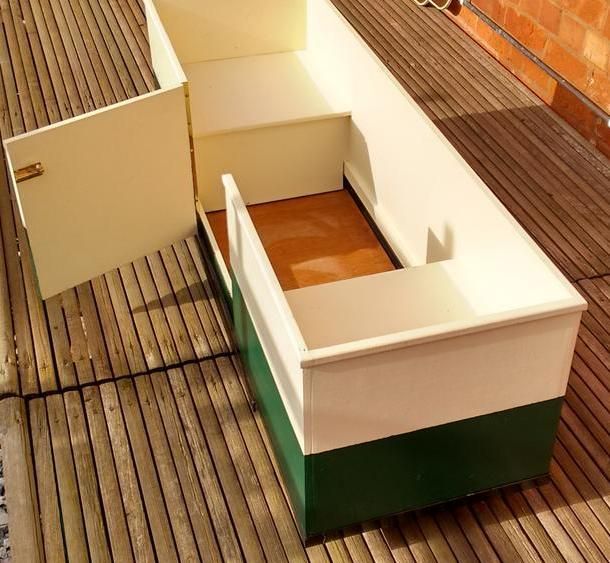
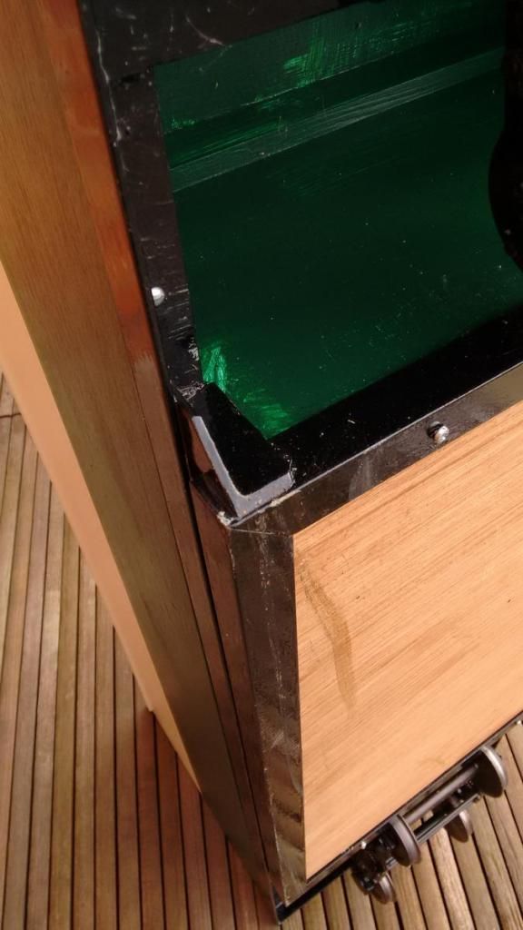
There will be cushions for the seats in due course. Finally for the inquisitive, a couple of pictures on the underneath showing the construction and bogies. One thing where this scale differs from all my previous modelling (in 4mm and 7mm) is that the couplings are attached to the frame as in real life, not the bogies.
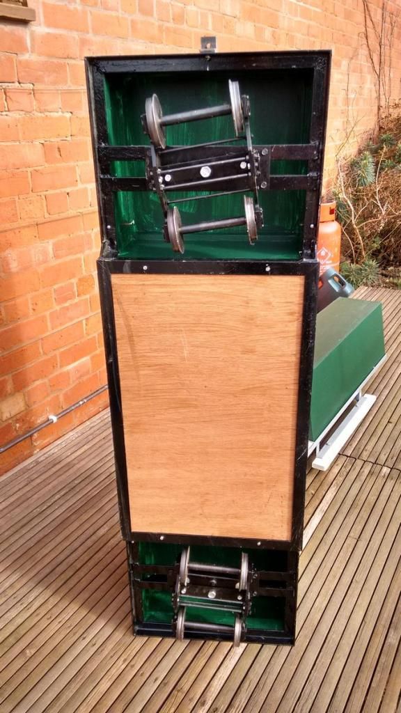
There is a sit astride riding truck in the background of one of these pictures. I'll get to that soon.
There will be cushions for the seats in due course. Finally for the inquisitive, a couple of pictures on the underneath showing the construction and bogies. One thing where this scale differs from all my previous modelling (in 4mm and 7mm) is that the couplings are attached to the frame as in real life, not the bogies.
There is a sit astride riding truck in the background of one of these pictures. I'll get to that soon.
The advantage of the tarmac is exactly that! It would come out cleanly for repairs to the track whereas concrete would not break cleanly unless cut properly with a specialist cutting disc. On the subject of the feathered edge between paint colours, what about a coach lining job using fine tape. Itd cover the joint cleanly and easily, then coat and seal with laquer! Easy!
P.S. My 'www' link shows my 5" gauge locos....
P.S. My 'www' link shows my 5" gauge locos....
The Hollycross Railway Company!
https://gardenrails.org/forum/viewtopic ... 41&t=10467
https://www.flickr.com/photos/pipps_trains/
https://gardenrails.org/forum/viewtopic ... 41&t=10467
https://www.flickr.com/photos/pipps_trains/
-
Dr. Bond of the DVLR

- Retired Director

- Posts: 4485
- Joined: Tue Jun 09, 2009 9:43 pm
- Location: Suffolk
- Contact:

-
Soar Valley Light
- Driver
- Posts: 1451
- Joined: Sun Dec 08, 2013 5:18 pm
- Location: North West Leicestershire
Tarmac is an interesting option and with track of this size might well be an option. It's flexibility, which is it's downfall in larger construction, may actually be it's strength here. The track would need to be on afirm base if you are to avoid road traffic 'rippling' the rails. (This is a problem on the standard gauge never mind something as small as this!)
I wonder if it would be possible to cast the concrete slab as planned but shutter out a recess where the railway will run. This would provide a firm base to support the track. I would imagine that a coat of binder would be required on the cured and dry concrete before tarmac is laid to give it something to grip to. I know very little amount the properties of tarmac and I'm not sure ho thin a depth you can lay before it breaks up under load. What is the height of the rail and steel gauge ties?. If this is too thin I can't see anything wrong with providing a deeper channel than the track actually needs and supporting it on shims. (Aluminium ones in your case I guess, to avoid corrosion problems)
What an interesting project this is!
Good luck,
Andrew
"Smith! Why do you only come to work four days a week?
"'cause I can't manage on three gaffer!"
"'cause I can't manage on three gaffer!"
Now for a bit of hard work. Digging the trench for the crossing across the drive. Although the drive is gravel, it is laid on a base of compacted MOT 1 sub-base and has been there for nearly 10 years. The stuff is intended to compact and form a solid base. I can confirm that it works.
You will be impressed to hear that I had the presence of mind to move the cars outside into the orchard before I dug the trench. Near thing though! As you can see from the tools lying beside the trench, this stuff took crowbars to break it up. Over a ton of stuff removed by this stage. The level of the rail will be about 50mm higher than the surface of the gravel, so there will be a slope on either side of the slab up to rail level. This is intended to prevent gravel gelling moved into the flangeways by passing vehicles. It also means that I don't have to dig the trench quite so deep. The shuttering will hold the slab while it sets then I will rake the gravel back into place against it.
I have decided to cast in solid concrete and hope the rails don't need attention for some time. I think I will use Tarmac for the tramway section in a future phase as that will be longer and have more joints and therefore have more risk of needing to dig part of it up.
Wickes is now down by a ton and a half of aggregate and several bags of cement. It never seemed this hard in 009.

I have acquired small amounts of tarmac (for drive repairs) from local road gangs in exchange for cups of tea and bacon sarnies when they have been working outside the house. (I also had a telegraph pole supplied and installed the same way) Its worth a little bribery!Interesting idea, tarmac. Not thought of that
failing that the ready to lay stuff works best on a nice hot day, after the drums have been in the sun for a few hours.
If at first you don't succeed, use a bigger hammer!
At last, here is a plan of the railway. It might help put the photos so far into context. As you can see, it is not the most complex track plan. Just a circuit with one siding for railing stock and potentially to keep another engine at some point. As the track goes down, this is what I should end up with.
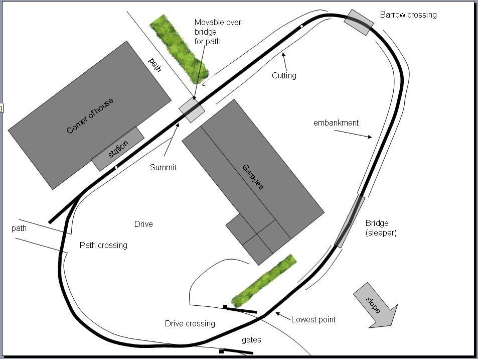
The circuit is about 120m round and because of the garage block, you can't see it all from any point (except a helicopter). I hope there will be sufficient interest with the crossings, bridge, embankments and cuttings. Also where the line passes between the garage and house it will be in quite a narrow gap, as a contrast to the open section to the right of the plan in the orchard.
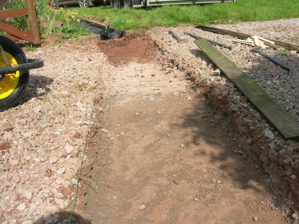
This probably gives some context. the viewpoint is from about the top edge of the plan halfway between the hedge and the right had side of the curve, looking down the slope, over the cutting to the embankment in the distance. The stack of bricks and wood on the right are against the back wall of the garages
The circuit is about 120m round and because of the garage block, you can't see it all from any point (except a helicopter). I hope there will be sufficient interest with the crossings, bridge, embankments and cuttings. Also where the line passes between the garage and house it will be in quite a narrow gap, as a contrast to the open section to the right of the plan in the orchard.
This probably gives some context. the viewpoint is from about the top edge of the plan halfway between the hedge and the right had side of the curve, looking down the slope, over the cutting to the embankment in the distance. The stack of bricks and wood on the right are against the back wall of the garages

Having dug a trench to trap any unwary visitors, or me if I forget about it coming home one evening, the next step is to install some shuttering to form the sides of the crossing. I'm not trying to get a geometrically perfect result here, as the sides will be up against the loose gravel of the driveway and not show clearly. Also, deeper down I'm happy for the concrete to flow to fill the shape of the trench to give a solid foundation.
Hardest thing here was fixing the pegs to attach the shuttering to. There is still some depth of MOT1 sub base below the bottom of the trench and it took a cold chisel and club hammer to make a hole for each peg.
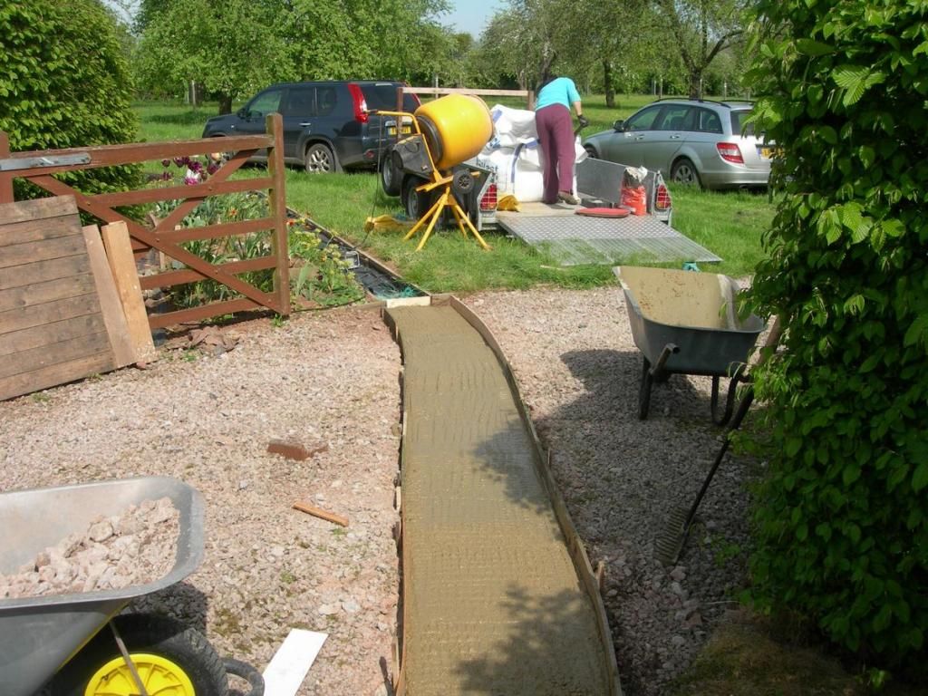
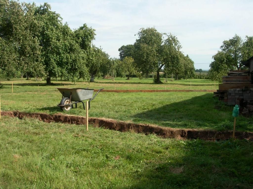
Casting the slab in progress, showing the work site in the orchard. Fortunately I have a cement mixer, left over from constructing a patio in a previous house. It was one of those cases where the mixer cost less than about 3 days of hire, so I bought it and ended up moving house with it! Still, a good excuse to use it again. Much better than a patio. The parts of a temporary bridge are leaning against the gate. It's surprising how everything is always on the wrong side of a trench like this, especially when it is full of wet concrete. Very useful implement to the right in this picture, a tarmac rake I bought from a rather shady looking character at a car boot sale. Perfect for agitating the concrete to settle and level it. There is more being mixed to lay and fill the trench before the first lot starts to set.
Hardest thing here was fixing the pegs to attach the shuttering to. There is still some depth of MOT1 sub base below the bottom of the trench and it took a cold chisel and club hammer to make a hole for each peg.
Casting the slab in progress, showing the work site in the orchard. Fortunately I have a cement mixer, left over from constructing a patio in a previous house. It was one of those cases where the mixer cost less than about 3 days of hire, so I bought it and ended up moving house with it! Still, a good excuse to use it again. Much better than a patio. The parts of a temporary bridge are leaning against the gate. It's surprising how everything is always on the wrong side of a trench like this, especially when it is full of wet concrete. Very useful implement to the right in this picture, a tarmac rake I bought from a rather shady looking character at a car boot sale. Perfect for agitating the concrete to settle and level it. There is more being mixed to lay and fill the trench before the first lot starts to set.
Who is online
Users browsing this forum: No registered users and 4 guests