What made you choose nails over screws - I've only used screws and while they are a bit more phaff during construction they do allow for a modicum of adjustment.
I really like the window bar gauge!
Construction of the MQR
-
Dr. Bond of the DVLR

- Retired Director

- Posts: 4485
- Joined: Tue Jun 09, 2009 9:43 pm
- Location: Suffolk
- Contact:

-
MDLR

- Driver

- Posts: 4027
- Joined: Thu Jan 15, 2009 10:38 pm
- Location: Near Ripley, Derbyshire, UK
- Contact:
We had a Wednesday Night Sleeper Gang, whoRichMQR:107372 wrote:For this phase about 900. I did them in batches and built track panels in between.
Would have probably gone crazy doing them all in one go.
1) Took last week's sleepers out of soak and allowed them to drain
2) drilled this week's sleepers ready for the Pandrol clip plates
3) took last weeks sleepers out of their soaking frame and put this week's sleepers in, then put the sleepers in to soak and topped up the creosote
4) screwed the Pandrol clip plates to last week's sleepers and added them to the pile.
The sleepers then went "down the line" in the PW train, as the panels were made up on site.

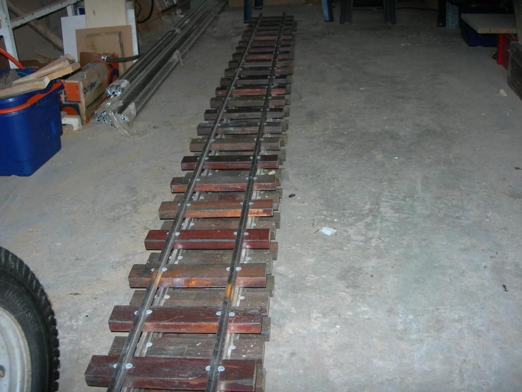
Back to the story ... Here are some completed straight panels. This stack will grow several feet high. You can see the bundle of loose rail on the left
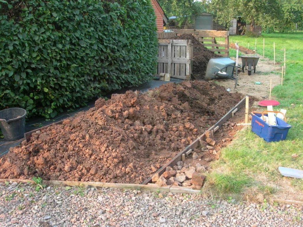
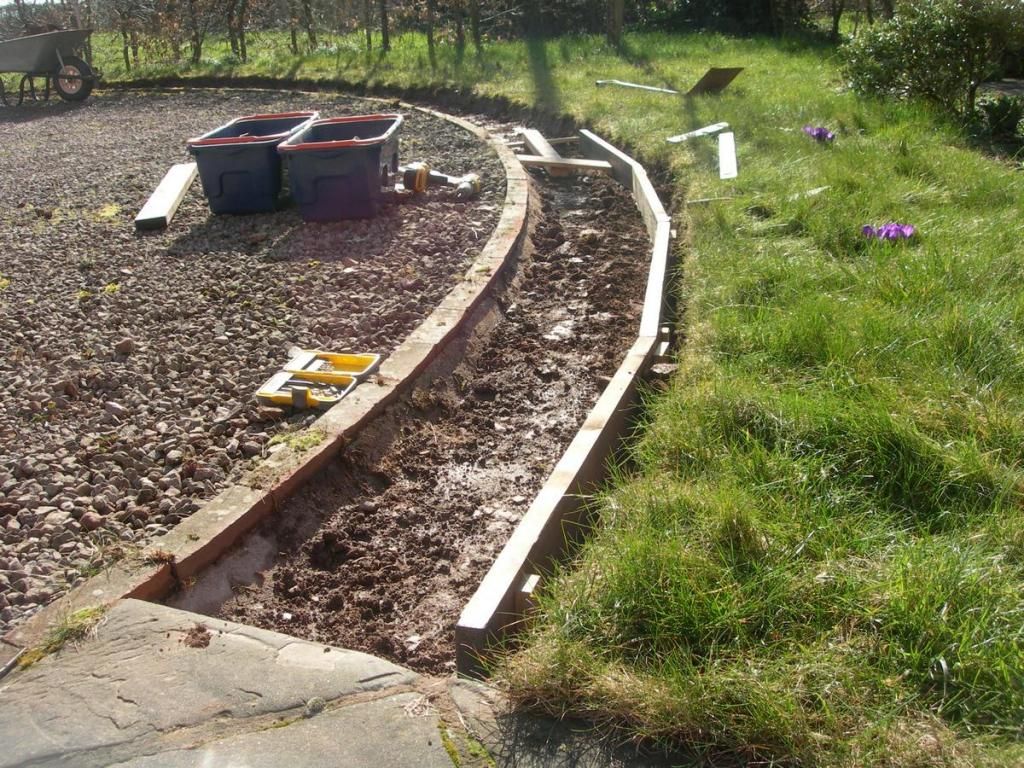
Back out on the trackbed, the embanked section is started. Having dug some cutting, the spoil has to go somewhere.
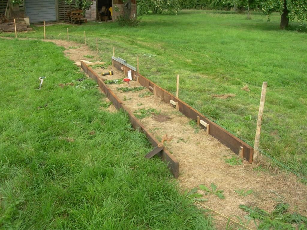
The sides are well treated timber that started life as warehouse shelving boards in a print factory. The pegs into the ground are untreated oak and about 9 inches long.Oak cross ties will be added just below ballast level to hold the sides vertical. Clearly, timber will only have a certain life. Maybe over time I will replace sections with stone walling. Right now, the cost is too high, and it takes too long.
Meanwhile, digging on the cutting section continues. You can see the embankment in the previous picture crossing the orchard in hte distance. The loop will run to the left of the frame to join up. On the extreme right is the back of the garages. The circuit runs right round the garages, crossing and circling the drive. That section is more complex and visible, so I'm not starting it until I've had some more practise in the orchard section.
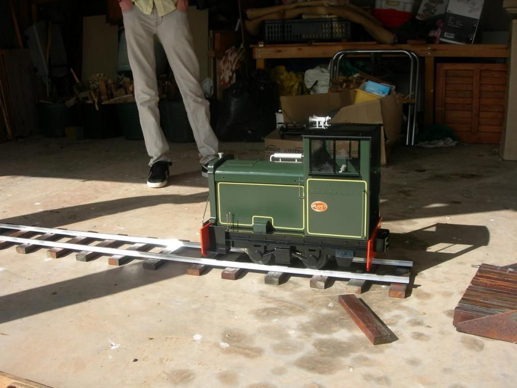
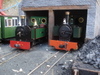
Of course, when you have completed a panel of track, you have to put it on the garage floor and put a loco on it. This is the works "diesel" - a Maxitrak Planet. I got it as a kit. In reality all you have to do is attach the motors and wire up the control panel. No more than an hours work. Great fun, but 3 meters of track isn't really enough!
Back out on the trackbed, the embanked section is started. Having dug some cutting, the spoil has to go somewhere.
The sides are well treated timber that started life as warehouse shelving boards in a print factory. The pegs into the ground are untreated oak and about 9 inches long.Oak cross ties will be added just below ballast level to hold the sides vertical. Clearly, timber will only have a certain life. Maybe over time I will replace sections with stone walling. Right now, the cost is too high, and it takes too long.
Meanwhile, digging on the cutting section continues. You can see the embankment in the previous picture crossing the orchard in hte distance. The loop will run to the left of the frame to join up. On the extreme right is the back of the garages. The circuit runs right round the garages, crossing and circling the drive. That section is more complex and visible, so I'm not starting it until I've had some more practise in the orchard section.
Of course, when you have completed a panel of track, you have to put it on the garage floor and put a loco on it. This is the works "diesel" - a Maxitrak Planet. I got it as a kit. In reality all you have to do is attach the motors and wire up the control panel. No more than an hours work. Great fun, but 3 meters of track isn't really enough!
-
andymctractor
- Trainee Driver

- Posts: 705
- Joined: Fri Feb 01, 2013 12:03 am
- Location: Suffolk, UK
- Contact:
There are many reasons why railway modellers of all types concentrate on trains but I think the railways themselves have more aesthetic potential. Of course I like trains but I have upset others in the hobby by suggesting that, for me at least, its more important that the model railway whatever scale gauge or standard, needs to be convincing. (Note I didn't say prototypical)RichMQR:107330 wrote:Passing trains are great, but I can also be happy walking from T-y-B to Tanygrisiau via Dduallt when no trains are running, just to see the track as there are footpaths near for most of the route. So, I want to create a railway that looks good when not in use, which is after all, most of the time!
When I was modelling 'electric mice' my view that a good model railway does not need to have something moving all the time, got me into trouble a number of times. A good model railway (garden or electric mice) can hold my attention with nothing running and a momentary pass of a convincing train is just a bonus.
At 16mm open days when it is survival of the fittest with columns of trains running in line ahead is just good fun and an excuse to see a vast range of often awe inspiring stock. However, my railway has been built to look convincing with no trains, after all that is how it is most of the time.
Regards
Andy McMahon
If it moves, salute it. If it doesn't move, paint it. (RN sailors basic skills course 1968)
Andy McMahon
If it moves, salute it. If it doesn't move, paint it. (RN sailors basic skills course 1968)

-
Peter Butler

- Driver
- Posts: 5253
- Joined: Sun Sep 09, 2012 10:33 pm
- Location: West Wales
Andy, I'm so pleased you have managed to put my feelings down in words too. Setting the scene is much more important than just having expensive items of stock which spend most of their time in boxes anyway!
I have said before that a test track on stilts does not represent a garden railway to me. To be complete it must have infrastructure and landscaping to give it a reason for being.
This railway should have it all... beautiful surroundings, practical purpose etc... looking forward to more.
I have said before that a test track on stilts does not represent a garden railway to me. To be complete it must have infrastructure and landscaping to give it a reason for being.
This railway should have it all... beautiful surroundings, practical purpose etc... looking forward to more.
The best things in life are free.... so why am I doing this?
-
Soar Valley Light

- Driver
- Posts: 1451
- Joined: Sun Dec 08, 2013 5:18 pm
- Location: North West Leicestershire
Andy, thanks for saying clearly what I was trying go get across! I think we may be at risk of starting a splinter group here of infrastructure enthusiasts. I hope I haven't set the expectation too high now for what I am trying to create.
One interesting factor I have found in 5 inch gauge construction is that while the track and locomotives are, as I am using 2 foot gauge prototypes, around 2.5 inches to the foot scale, the drivers and passengers are 12 inches to the foot. This creates a strange set of clearance requirements which prevent the construction of some features I would like. Basically things you go over - embankments and bridges can be reasonably realistic, things you go through or under - cuttings or over-bridges can not. It also means that rolling stock has to be either to scale for visual effect, or designed to carry Human occupants. There can be compromises (small children fit well in 3 ton slate wagons), but few of them are convincing.
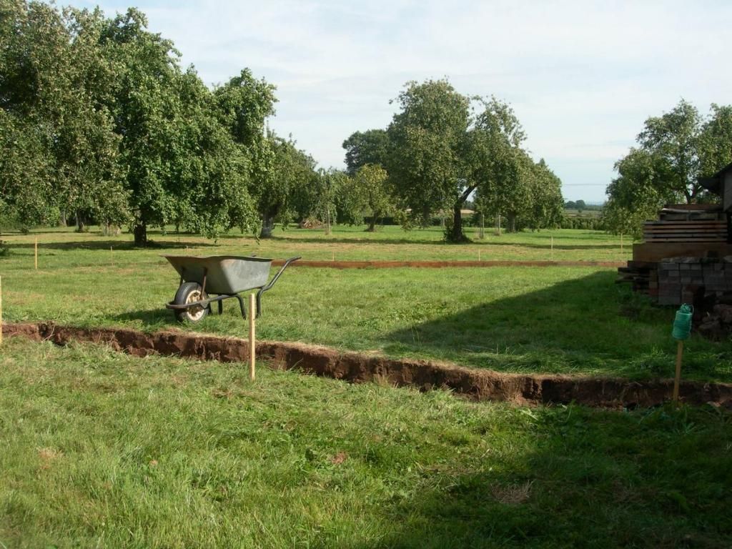
Here is the point at which the line will have to cross the drive to the house. You can see the earlier construction of the embankment beyond the wheelbarrows. To the left is a flowerbed made out of spoil. About where the upright barrow is standing is the low point of the line. There will be a bridge here.
One interesting factor I have found in 5 inch gauge construction is that while the track and locomotives are, as I am using 2 foot gauge prototypes, around 2.5 inches to the foot scale, the drivers and passengers are 12 inches to the foot. This creates a strange set of clearance requirements which prevent the construction of some features I would like. Basically things you go over - embankments and bridges can be reasonably realistic, things you go through or under - cuttings or over-bridges can not. It also means that rolling stock has to be either to scale for visual effect, or designed to carry Human occupants. There can be compromises (small children fit well in 3 ton slate wagons), but few of them are convincing.
Here is the point at which the line will have to cross the drive to the house. You can see the earlier construction of the embankment beyond the wheelbarrows. To the left is a flowerbed made out of spoil. About where the upright barrow is standing is the low point of the line. There will be a bridge here.
A clearance test, with a panel of track laid loose on the unprepared roadbed. The plan is to compact the earth/hardcore to give space for a 2 inch ballast bed on which the track will be laid and then ballasted. That should bring the top of the sleepers to about level with the top of the timber edges. The truck in the picture is a standard Maxitrak chassis.
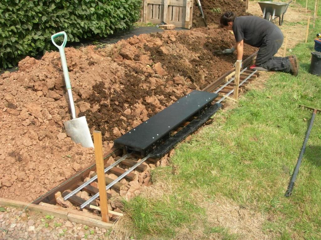
The flowerbed has now been graded to give clearance at the lower level. This will have just low growing ground-cover type plants.
In the distance you can see a gap in the wooden embankment edging and a second-hand standard gauge sleeper lying to the left. This will form a low bridge in the gap in the embankment. You can see the gradient marker posts from the original survey still in place where the trackbed is not yet built. Also a spirit level across the embankment sides. Very important to keep cross levels correct. There sill be adjusted by small packing pieces to give superelevation on the curves.
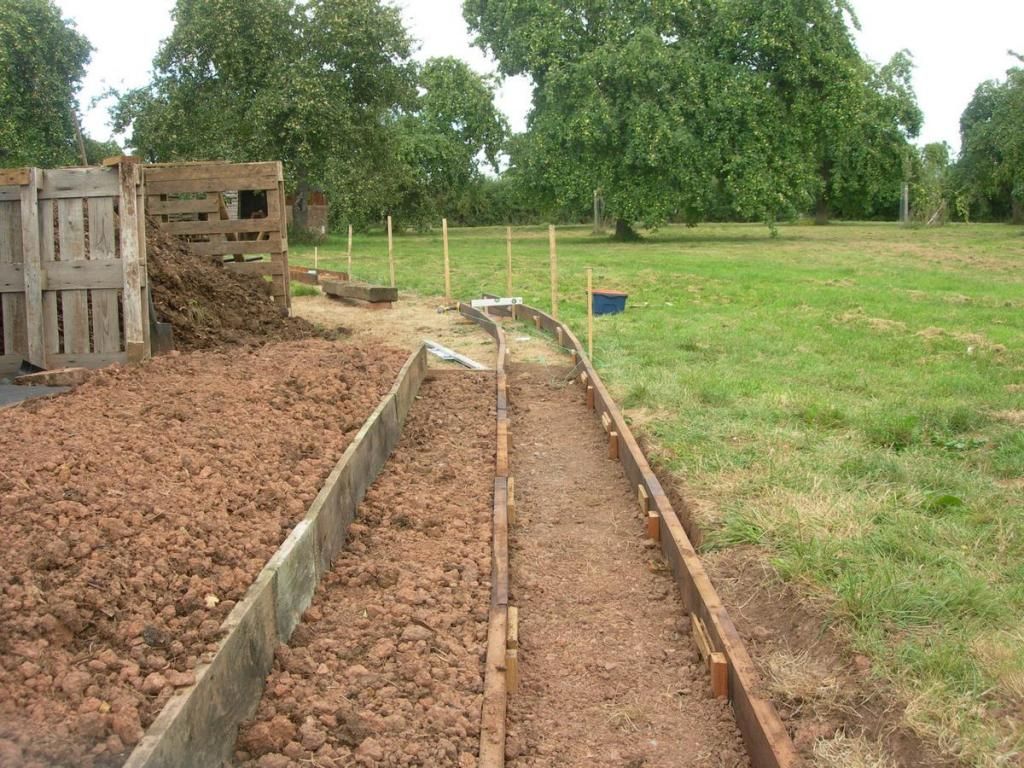

Construction continues. All of a sudden I have increased admiration for those volunteers who, 50 years ago, near Dduallt decided to pick up a shovel and dig a new railway! Even on 5inch gauge, this is hard work, and I haven't got Welsh rock to contend with! My previous efforts in NG railway construction have been 009. The difference is immense.
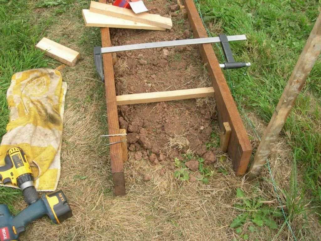
You can see here that the embankment is rising in anticipation of the slope in the ground behind the camera. You can also see the cross bracing between the sides necessary to prevent them spreading when the fill and ballast is added.
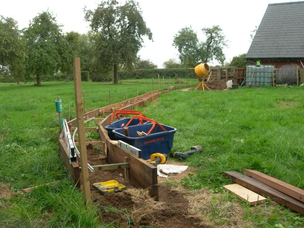
Yes, that is a cement mixer in the background. There is at least a ton of concrete to go into this soon. There is a loose bit of rail curved to the planned radius just as a sanity check
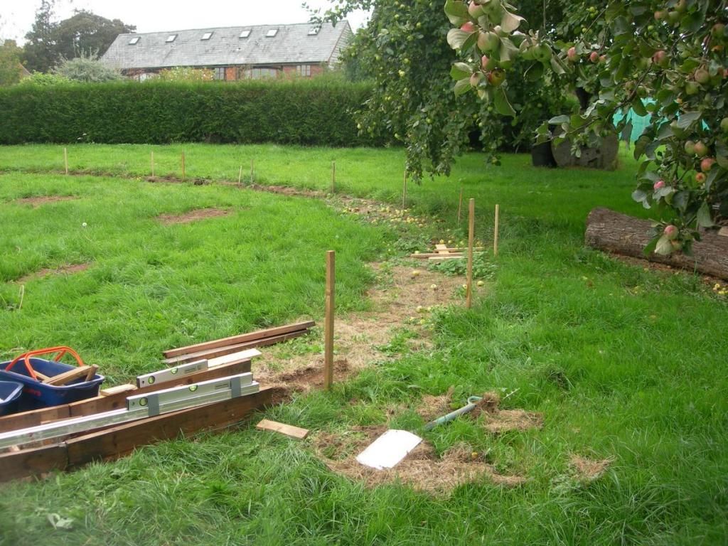
Looking the other way you can see that the ground is rising and the cutting is ahead. Just about where the wooden profile gauge is lying on the ground is the point where the line will be at ground level (for about a metre!) there will be a level crossing here for foot traffic.
You can see here that the embankment is rising in anticipation of the slope in the ground behind the camera. You can also see the cross bracing between the sides necessary to prevent them spreading when the fill and ballast is added.
Yes, that is a cement mixer in the background. There is at least a ton of concrete to go into this soon. There is a loose bit of rail curved to the planned radius just as a sanity check
Looking the other way you can see that the ground is rising and the cutting is ahead. Just about where the wooden profile gauge is lying on the ground is the point where the line will be at ground level (for about a metre!) there will be a level crossing here for foot traffic.
So, where was I? - You've seen the construction of straight track and also that much of the earthworks so far are curved embankments. This means I'm going to need some curved track. Now, although a 3m length of 16mm profile aluminium rail seems quite flexible, it certainly isn't like flexi track. Even if you bend it. it wants to be straight again. The answer is a rail bender. Of course you can buy these, but you have probably realised by now that I prefer to save the money and make this kind of thing from assorted junk, so here is a Mk 1 rail bender.
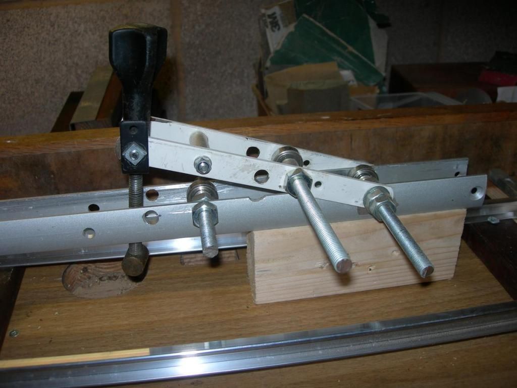
The actual bending is done by the three roller bearings on the threaded rods. The amount of curvature is controlled by screwing down the black knob on the vertical threaded rod. (this actually used to control the blade position on a lawnmower!) The rail is then run through this several times, gradually tightening down the knob until the curve is right. This is checked by trying the curve in position out on the line. The ball bearings run in the web of the rail.
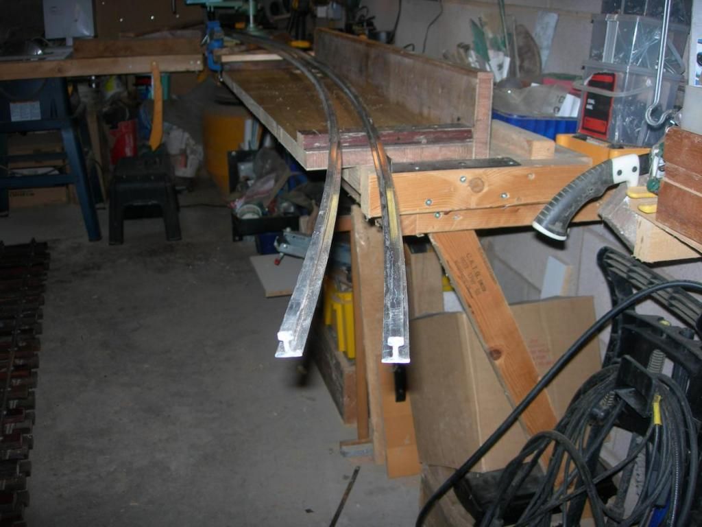
Here are two curved rails ready for the sleepers
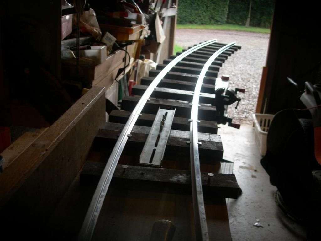
and here the panel takes shape
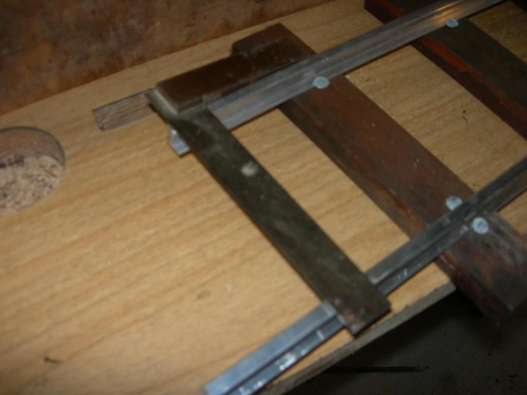
Of course, on a curve the inner rail needs shortening, so here is a set square showing where to cut the rail. The other end was started with the rails squared off.
and here in a mitre box to make sure the ends are square
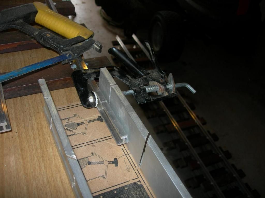
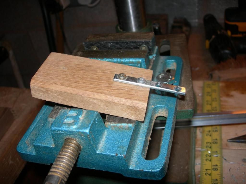
Finally, the rail ends need drilling for the fishplates. I drill the holes somewhat oversize to allow for expansion, and also leave a 1mm gap between rail ends. This fishplate has the holes opened out a bit for using as a jig to drill the rail ends. When the wooden block is against the rail end, the position is right to drill through the rail
The actual bending is done by the three roller bearings on the threaded rods. The amount of curvature is controlled by screwing down the black knob on the vertical threaded rod. (this actually used to control the blade position on a lawnmower!) The rail is then run through this several times, gradually tightening down the knob until the curve is right. This is checked by trying the curve in position out on the line. The ball bearings run in the web of the rail.
Here are two curved rails ready for the sleepers
and here the panel takes shape
Of course, on a curve the inner rail needs shortening, so here is a set square showing where to cut the rail. The other end was started with the rails squared off.
and here in a mitre box to make sure the ends are square
Finally, the rail ends need drilling for the fishplates. I drill the holes somewhat oversize to allow for expansion, and also leave a 1mm gap between rail ends. This fishplate has the holes opened out a bit for using as a jig to drill the rail ends. When the wooden block is against the rail end, the position is right to drill through the rail
-
Soar Valley Light
- Driver
- Posts: 1451
- Joined: Sun Dec 08, 2013 5:18 pm
- Location: North West Leicestershire
Very interesting (as the whole topic has been), we used a jig very similar for drilling rails for fishplates on 15 inch gauge at the Ravenglass and Eskdale Railway, but for sawing we hire in a rail saw designed for standard gauge, fitted with a modified clamp. Knife through butter is a good analogy....
"What the hell is that?"
"It's a model icebreaker sir."
"It's a bit big isn't it?"
"It's a full scale model sir....."
"It's a model icebreaker sir."
"It's a bit big isn't it?"
"It's a full scale model sir....."
Thanks for the comments. Something that went through these rails like butter would be useful! They aren't really that hard, but after a few of them it feels like hard work. I don't get to Ravenglass as often as I'd like, but always love the line when I make it that far. Somehow, travelling from the south, the magnetic attraction of North Wales always seems to deflect me to the west!
I understand what you mean, for us its 1 1/2 hours to Ravenglass or 3 hours (if you're lucky) to Porthmadog. Saying that, I feel fairly lucky to live somewhere that make day visits to both doable, albeit that North Wales is a very long day out.
"What the hell is that?"
"It's a model icebreaker sir."
"It's a bit big isn't it?"
"It's a full scale model sir....."
"It's a model icebreaker sir."
"It's a bit big isn't it?"
"It's a full scale model sir....."
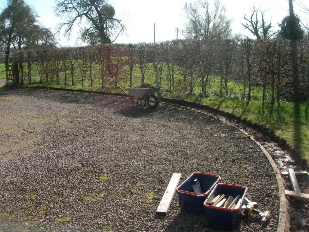
Now, having mastered curves,time to build more curved trackbed. Here we are on the house side of the circuit, skirting the drive.
Here there is a brick edge already in place so the formation just needs one wooden side. In the middle distance you can see a width spacer. I have several of these to try to keep things looking neat and even particularly on this rather visible section.
Just out of shot beyond the wheelbarrow is one of the major engineering works that will be needed , the level crossing of the drive and behind the camera the crossing of the path to the front door.
I like the look of the curve on this section
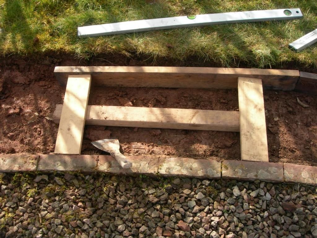
Here is a closeup of the spacers
Here there is a brick edge already in place so the formation just needs one wooden side. In the middle distance you can see a width spacer. I have several of these to try to keep things looking neat and even particularly on this rather visible section.
Just out of shot beyond the wheelbarrow is one of the major engineering works that will be needed , the level crossing of the drive and behind the camera the crossing of the path to the front door.
I like the look of the curve on this section
Here is a closeup of the spacers
Who is online
Users browsing this forum: No registered users and 2 guests