Live Diesel 1/12th scale

A place for discussing diverse methods of powering locomotives, such as Internal Combustion, Wind, etc...
User avatar
dewintondave
Trainee Driver
Trainee Driver
Posts: 697
Joined: Mon Mar 07, 2011 8:52 am
Location: New Zealand

Post by dewintondave » Sun Mar 30, 2014 8:20 am

After yet more months of behind the scenes work I can now reveal the final transmission set-up.

Image

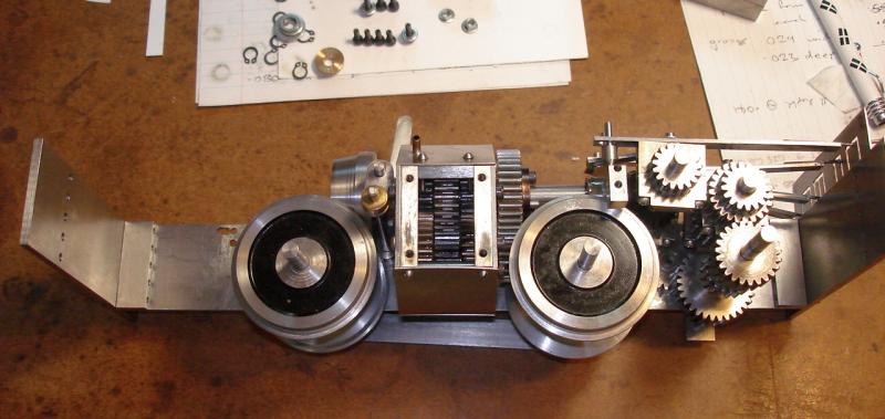
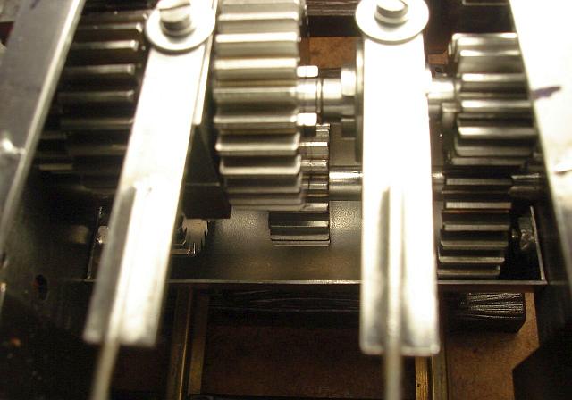
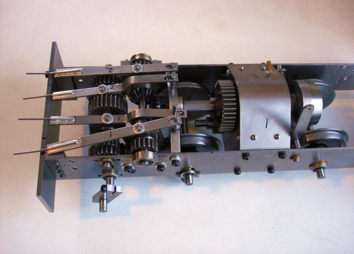
The gears are in constant mesh and are connected to their shafts by sliding dog-clutches. The gears on the jackshaft are Loctited to the shaft, the other gears rotate on their shaft unless engaged by a clutch.

Image

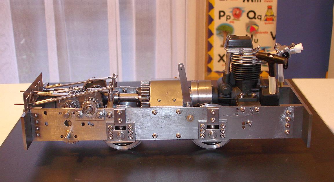
I have built a three-speed gearbox.

Image

As with Dave Watkins' "Detritus", reversing is accomplished by the opposing bevel gears. Unlike an automotive gearbox the three gears are available in forwards and reverse. The bevel gears were bought on eBay, and are the only gears I didn't cut myself.

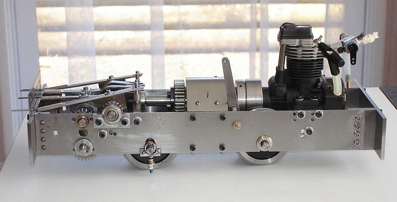
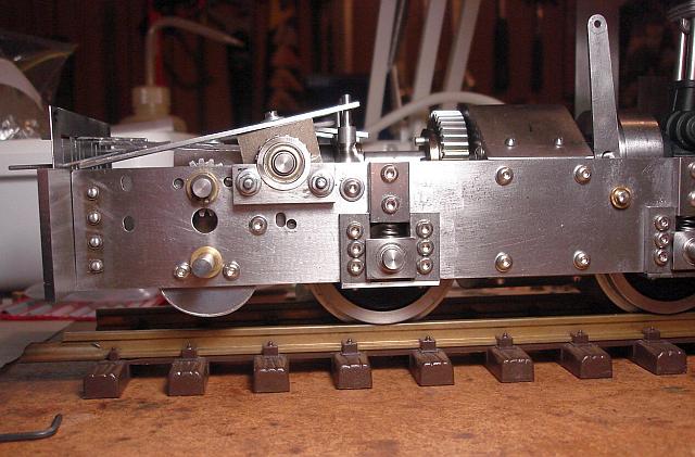
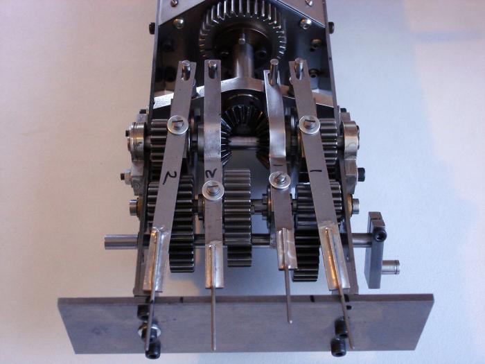
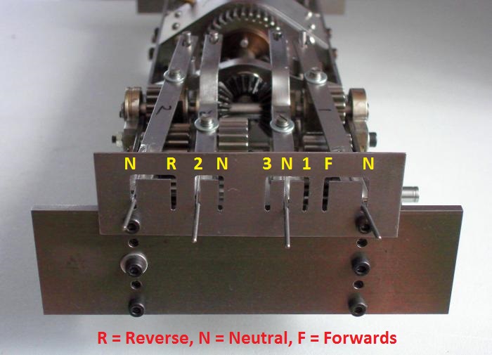
There are four gear levers, one for reverse, one for 2nd gear, one for 3rd & 1st gears, and one for forward gear. I have to bring reverse fully out of gear before engaging forwards or else both gears will be engaged, and that would cause issues :)


Best wishes,

Dave.
Last edited by dewintondave on Sun Feb 09, 2020 1:42 am, edited 1 time in total.

User avatar
GTB
Driver
Driver
Posts: 1559
Joined: Sat Mar 05, 2011 2:46 pm
Location: Australia

Post by GTB » Sun Mar 30, 2014 11:59 am

dewintondave:98587 wrote: I have to bring reverse fully out of gear before engaging forwards or else both gears will be engaged, and that would cause issues  :)
Very nice work.

I've not had to machine gears yet, are you using commercial volute cutters, or do you make your own?

It's a bit hard to work out from the photos, but could you fix the bevel gears on a sliding sleeve so they move together?

That would mean only one lever is needed for direction change, removing the risk of putting a few gears into low earth orbit in a moment of distraction.......

Graeme

Big Jim
Moderator
Moderator
Posts: 2694
Joined: Sat Jul 06, 2013 5:28 pm
Location: Near Llanelli

Post by Big Jim » Sun Mar 30, 2014 8:54 pm

Wow.
I take my hat off to you.
If at first you don't succeed, use a bigger hammer!

User avatar
dewintondave
Trainee Driver
Trainee Driver
Posts: 697
Joined: Mon Mar 07, 2011 8:52 am
Location: New Zealand

Post by dewintondave » Mon Mar 31, 2014 8:18 am

GTB:98594 wrote:
I've not had to machine gears yet, are you using commercial volute cutters, or do you make your own?

It's a bit hard to work out from the photos, but could you fix the bevel gears on a sliding sleeve so they move together?
Hi Graeme,

I'm using a homemade cutter as detailed in this excellent resource: http://www.helicron.net/workshop/gearcutting/method/

It's very satisfying making gears, but very slow. Some of the gears were made four at a time. I ended up roughing out each tooth in one pass at .09" depth with a single tooth cutter, then finishing in one pass at .097" with the hob detailed on the website. The gears come out heavily burred and require about an hours fettling.

The bevel gears are both in mesh all the time and freely rotating on the shaft. The dog clutches need about 2.5 mm of movement to bring them fully in and out of engagement. If the levers were connected I'd need about 5 mm of travel at each side so there wouldn't be any double engagement. I just didn't have the room.

Best wishes,
Dave.
Best wishes,
Dave

User avatar
GTB
Driver
Driver
Posts: 1559
Joined: Sat Mar 05, 2011 2:46 pm
Location: Australia

Post by GTB » Mon Mar 31, 2014 10:23 am

dewintondave:98642 wrote: I'm using a homemade cutter as detailed in this excellent resource: http://www.helicron.net/workshop/gearcutting/method/  
Thanks Dave,

I found that site a while back while searching for something else and have a printout stashed in the files. Good to know the method works, as it seems to be within the limits of my machining abilities......

Machining burrs are one of those things sent to try us, I think. :roll:

Graeme

User avatar
Dannypenguin
Trainee Driver
Trainee Driver
Posts: 632
Joined: Tue Feb 26, 2013 9:57 am
Location: Forest of Dean, UK
Contact:

Post by Dannypenguin » Mon Mar 31, 2014 11:39 am

Thats impressive :thumbright:
Dan

Visit the PFLR website - http://poultonfarmlightrailway.webs.com/
Dean Forest Railway Society website - http://dfrsociety.org/

User avatar
dewintondave
Trainee Driver
Trainee Driver
Posts: 697
Joined: Mon Mar 07, 2011 8:52 am
Location: New Zealand

Post by dewintondave » Sat Apr 05, 2014 7:54 am

I've had to extend the frames forwards 10 mm.  The front of the carby was directly inline with the front buffer beam.  The engine couldn't go back any further...

The chassis with one side frame off for lengthening.
Image

Now the frame is 10 mm longer.
Image

The graceful new lines.
Image

Best wishes,
Dave
Last edited by dewintondave on Sun Feb 09, 2020 1:47 am, edited 1 time in total.
Best wishes,
Dave

User avatar
dewintondave
Trainee Driver
Trainee Driver
Posts: 697
Joined: Mon Mar 07, 2011 8:52 am
Location: New Zealand

Post by dewintondave » Sun Apr 13, 2014 8:04 am

The rear suspension is far too bouncy. Some things are good being bouncy but not this loco.


As a trial I had used a gauge 1 inside frame type suspension, it doesn't look the best on this application.

Here we are, I'm making horn plates for a new suspension arrangement on both axles.

Image

Best wishes,
Dave.
Last edited by dewintondave on Sun Feb 09, 2020 1:52 am, edited 1 time in total.
Best wishes,
Dave

User avatar
Dr. Bond of the DVLR
Retired Director
Retired Director
Posts: 4485
Joined: Tue Jun 09, 2009 9:43 pm
Location: Suffolk
Contact:

Post by Dr. Bond of the DVLR » Sun Apr 13, 2014 11:11 am

How does the new system work - equalizing beams?
Image
The railway which people forgot
(to build)

User avatar
andymctractor
Trainee Driver
Trainee Driver
Posts: 705
Joined: Fri Feb 01, 2013 12:03 am
Location: Suffolk, UK
Contact:

Post by andymctractor » Sun Apr 13, 2014 4:48 pm

Superb stuff.  
That is the only loco chassis I've ever seen in any scale that could not look any better by fitting a body.  Its almost a shame to cover it up.
Regards
Andy McMahon

If it moves, salute it.  If it doesn't move, paint it. (RN sailors basic skills course 1968)

User avatar
dewintondave
Trainee Driver
Trainee Driver
Posts: 697
Joined: Mon Mar 07, 2011 8:52 am
Location: New Zealand

Post by dewintondave » Mon Apr 14, 2014 8:44 am

Mr. Bond of the DVLR:99338 wrote:How does the new system work - equalizing beams?
Axle boxes sliding between the horn plates. I want to try a leaf spring arrangement, if that fails it will have to be the usual coil springs on top of the axle boxes.

I was recently re-watching the 16 mm assoc videos, I loved your DVLR films they were magic :-)
Last edited by dewintondave on Sun Feb 09, 2020 1:59 am, edited 1 time in total.
Best wishes,
Dave

User avatar
dewintondave
Trainee Driver
Trainee Driver
Posts: 697
Joined: Mon Mar 07, 2011 8:52 am
Location: New Zealand

Post by dewintondave » Mon Apr 14, 2014 8:48 am

andymctractor:99353 wrote:Superb stuff.  
That is the only loco chassis I've ever seen in any scale that could not look any better by fitting a body.  Its almost a shame to cover it up.
Thanks Andy, that's great.

There will be plenty of works to see through the cab doors. I didn't manage to keep everything below floor height
Last edited by dewintondave on Sun Feb 09, 2020 2:00 am, edited 1 time in total.
Best wishes,
Dave

User avatar
dewintondave
Trainee Driver
Trainee Driver
Posts: 697
Joined: Mon Mar 07, 2011 8:52 am
Location: New Zealand

Post by dewintondave » Sun Apr 20, 2014 8:35 am

Milling the axle box slots out of the first frame side.

Image

Here's the new horn plates in position on one of the frames.

Front
Image

Back
Image

My project this week is to make some axle boxes.
Last edited by dewintondave on Sun Feb 09, 2020 2:05 am, edited 1 time in total.
Best wishes,
Dave

User avatar
dewintondave
Trainee Driver
Trainee Driver
Posts: 697
Joined: Mon Mar 07, 2011 8:52 am
Location: New Zealand

Post by dewintondave » Wed Apr 23, 2014 5:53 am

Here are two new axle boxes. I shall think about the springing and the keeper plate before I start on the other frame.

Image
Last edited by dewintondave on Sun Feb 09, 2020 2:07 am, edited 1 time in total.
Best wishes,
Dave

User avatar
dewintondave
Trainee Driver
Trainee Driver
Posts: 697
Joined: Mon Mar 07, 2011 8:52 am
Location: New Zealand

Post by dewintondave » Sat Apr 26, 2014 5:50 am

I had to use coil springs as I couldn't fit leaf springs in.

Image

Image

Now I have to do it all over again for the second frame
Last edited by dewintondave on Sun Feb 09, 2020 2:10 am, edited 1 time in total.
Best wishes,
Dave

User avatar
dewintondave
Trainee Driver
Trainee Driver
Posts: 697
Joined: Mon Mar 07, 2011 8:52 am
Location: New Zealand

Post by dewintondave » Sat May 17, 2014 10:17 am

Finally the chassis is rolling again... I had to modify the clutch actuator shaft to allow full travel on the front axle boxes (the wheel flanges were contacting it) that took three days after I had worked out what to do! I've switched the fasteners to mushroom-headed screws, I think they look better.

Image

I need to make slightly longer axles now as the axle boxes stand out further than previous bushes.

There are a lot of no longer used holes in the chassis that need filling...
Last edited by dewintondave on Sun Feb 09, 2020 2:12 am, edited 1 time in total.
Best wishes,
Dave

User avatar
Dr. Bond of the DVLR
Retired Director
Retired Director
Posts: 4485
Joined: Tue Jun 09, 2009 9:43 pm
Location: Suffolk
Contact:

Post by Dr. Bond of the DVLR » Sat May 17, 2014 11:12 am

Very smart. Ive always wondered - what is the best way to fill holes in the frames?
Image
The railway which people forgot
(to build)

User avatar
dewintondave
Trainee Driver
Trainee Driver
Posts: 697
Joined: Mon Mar 07, 2011 8:52 am
Location: New Zealand

Post by dewintondave » Wed May 21, 2014 10:35 am

Mr. Bond of the DVLR:100724 wrote:Ive always wondered - what is the best way to fill holes in the frames?
Well, I've managed to fill 4 with some more screws.

Here's a cover for the lower gears, I could imagine that vegetation would get crunched up by the large 1st gear.
Image

The cover fitted.
Image

Looking down on the cover, we could fill it with oil too.
Image
Last edited by dewintondave on Sun Feb 09, 2020 2:16 am, edited 1 time in total.
Best wishes,
Dave

User avatar
Dr. Bond of the DVLR
Retired Director
Retired Director
Posts: 4485
Joined: Tue Jun 09, 2009 9:43 pm
Location: Suffolk
Contact:

Post by Dr. Bond of the DVLR » Wed May 21, 2014 6:06 pm

ah right - just tap and screw in a bolt. With regards the protector/ oil bath - do you think a drain valve for changing the oil would be required or would you syringe it out?
I can't wait to see a video of the finished thing!
Image
The railway which people forgot
(to build)

User avatar
AndrewGVT
Cleaner
Cleaner
Posts: 54
Joined: Tue May 21, 2013 7:45 pm
Location: Hampshire
Contact:

Post by AndrewGVT » Wed May 21, 2014 6:41 pm

Smashing work!!! :D
Andrew
=============
Proper engineering techniques; use a hammer, if that fails, get a bigger hammer.

Post Reply

Who is online

Users browsing this forum: No registered users and 4 guests