The New??? Mamod Locomotive Mark II

A very popular starting point for Live Steam. With their low cost comes a number of problems which can be discussed here
User avatar
Chris Cairns
Driver
Driver
Posts: 2366
Joined: Mon Oct 29, 2007 7:25 pm
Location: Glasgow, Scotland

Post by Chris Cairns » Fri Sep 14, 2012 1:59 pm

dougrail wrote:Yes, I was [and still am] inexperienced at this game...
Doug you have certainly built up a lot of experience with Mamodification in a very short time so you are no longer "inexperienced". I particularly enjoy reading up about your trials & tribulations with regards to painting as that is one area I have not spent much time on so far.

As you have found Mamods are very individual due to the inaccuracy of the manufacturing tolerances, and whilst some will run great without any modification, others will refuse to run until vast amounts of money & upgrades are carried out. I still have a couple that have been full time residents of my 'workshop' and slowly tinker away at them to get them to run better when time permits.
Annie wrote:I've got a 234 that's missing its boiler and cylinders that I want to rebuild
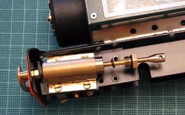
The Bowman 234 is an impressive loco when it is running well. I've repaired mine, and whilst it runs great on blocks (love the throaty noise the exhaust pipes in the chimney make), it barely runs one full oval on my track without being pushed. Needs some more work done on the burner and the piston oiler felt pads.

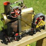
Sadly there is virtually no information on the Markie replica Bowman locos on-line. I've seen photos of their 234 look-alike but I understand they made a 265 look-alike as well.

Chris Cairns.

User avatar
Chris Cairns
Driver
Driver
Posts: 2366
Joined: Mon Oct 29, 2007 7:25 pm
Location: Glasgow, Scotland

Post by Chris Cairns » Wed Dec 19, 2012 6:18 pm

Crackingjob wrote:and what the thread sizes?
Mamod have replied that the false steam dome thread size is 7/16" BSP.

Chris Cairns.

User avatar
mikewakefielduk@btinterne
Fireman
Fireman
Posts: 309
Joined: Wed Nov 28, 2012 1:43 pm
Location: Shropshire

Mk11 lubricator

Post by mikewakefielduk@btinterne » Wed Dec 19, 2012 9:21 pm

I've got my hands on a spare Mk11 lubricator and I'm trying to get my head around how it works and how it could be improved.

For those of you who haven't examined these things, it consists of a hollow rectangular box with the steam inlet on the top and a filler plug about half way up one side. The steam outlet pipe comes in at the bottom corner and projects about half way up inside the box. You put 2.5 cc of steam oil which I guess fills the box to up to about the level of the bottom of the filler plug.

So what I think happens is the high pressure steam comes into the space above the oil before entering the steam outlet pipe. Because the surface area of the oil is large it quickly mixes with the steam and is carried away to lubricate the cylinders but this results in it being used up quickly.

So how could this be improved? Any suggestions/comments gratefully received. Its certainly nothing like the one on my Cheddar Iver (which seems to work really well).

Mike Wakefield

User avatar
Chris Cairns
Driver
Driver
Posts: 2366
Joined: Mon Oct 29, 2007 7:25 pm
Location: Glasgow, Scotland

Post by Chris Cairns » Thu Dec 20, 2012 7:19 am

The Cheddar Models, IP Engineering, PPS Steam, RWM Steam & Roundhouse Engineering displacement lubricators share a common design, with most having the hole on the underside of the steam pipe. Not all are fitted with a drain screw.

Image
© Roundhouse Engineering.

So the main steam pipe is continuous through the lubricator body with a graduated hole allowing some steam to enter the body, condense into water which displaces the oil. The size of the hole is certainly smaller than the internal diameter of the steam pipe, and when Roundhouse changed to 220 oil from 460 oil they had to make that hole smaller. Some lubricators have an adjustable needle valve on that hole to control the flow of oil.

Not to scale but here is the Mamod Mark II lubricator.

Image

The main steam pipe is screwed into a gland fitting on the top of the lubricator, and a separate overflow style steam exit pipe is fitted internally. On my Mark II this exit pipe goes up pretty close to the top of the box so if they now only going half way up then that makes the early displacement of the oil even worse. When you fill this lubricator you tend to put the loco on its side so some of the oil may be making its way down the overflow steam exit pipe during that process. Note that compared to the Roundhouse type above there is a much bigger empty space to be filled by the steam and although not confirmed I suspect that the steam exit pipe has no restriction thus it has the normal sized internal diameter hole, which is bigger than the one used in the Roundhouse type.

So what is needed is a continuous steam pipe through the lubricator with a smaller graduated hole near the top of that pipe. This then means that the current lubricator would be too big as filling it up towards that hole would use a lot more steam oil.

Image

And the other problem is that the filler plug is mounted on the side and it is hollow. Whilst the new Thomas Telford lubricator after No.20 will have a drain screw on the bottom it still has the hollow filler plug on the side. I find that drain screws are not that effective at removing the water without losing some oil as well, so use a syringe to remove the water (you need to do that with your Cheddar Iver loco and Cheddar Models supplied a syringe and blunt needle for that purpose). So keeping the hollow filler plug on the side means it can be a bit messy emptying/refilling and probably losing some oil as well.

Chris Cairns.

bessytractor
Trainee Driver
Trainee Driver
Posts: 677
Joined: Wed Nov 14, 2007 2:34 pm

Post by bessytractor » Thu Dec 20, 2012 9:59 pm

in answer to the original suggestion, I could make you an adaptor.
proudly flying in the face of convention

User avatar
mikewakefielduk@btinterne
Fireman
Fireman
Posts: 309
Joined: Wed Nov 28, 2012 1:43 pm
Location: Shropshire

Post by mikewakefielduk@btinterne » Fri Dec 21, 2012 10:47 am

I'd thought of doing it myself as soldering small things is something I do for a living (I'm a clock restorer) but it won't be easy. I suspect you'll have to partly dismantle it. Not sure if you can see from the photo but it looks as though the two ends of the box have been soft soldered on before the majority of it was painted.

Image

The hole in the bottom is where the steam line exits and the threaded portion on top is where steam comes in. Although the latter is hexagonal to take a spanner its also soldered into the lubricator box.

Mike

User avatar
mikewakefielduk@btinterne
Fireman
Fireman
Posts: 309
Joined: Wed Nov 28, 2012 1:43 pm
Location: Shropshire

Post by mikewakefielduk@btinterne » Fri Jan 04, 2013 11:02 pm

My Mk11 cab is slightly tapered - look from the back towards the front its between 2 and 3mm wider at the bottom than the top.

Can somebody else check theirs to confirm whether they're all like that or its just mine and it was made in a hurry.

Thanks


Mike

User avatar
Chris Cairns
Driver
Driver
Posts: 2366
Joined: Mon Oct 29, 2007 7:25 pm
Location: Glasgow, Scotland

Post by Chris Cairns » Fri Jan 04, 2013 11:53 pm

Mike,

Surely not another one for your growing list of Quality Control problems.

Just checked my Mark II. At the top front of the cab it measures 80mm to the outside of the cab sides. At the cab rear at the bottom besides the rivets on the buffer beam it also measures 80mm to the outside of the cab sides. Initially on checking the cab rear at the top it measured 79mm but the rivet at the back left on the cab roof is loose so I can push the cab side out on that side so it will measure 80mm to the outside of the cab sides.

So mine is effectively square at 80mm all round.

Chris Cairns.

User avatar
mikewakefielduk@btinterne
Fireman
Fireman
Posts: 309
Joined: Wed Nov 28, 2012 1:43 pm
Location: Shropshire

Post by mikewakefielduk@btinterne » Sat Jan 05, 2013 9:26 pm

A bit of brute force and ignorance and I managed to loosen up the pop rivets enough to move the cab sides out to vertical, and now all is near enough square. It never occurred to me that the holes would be so much larger than the rivets. I wonder why?


Mike

User avatar
Chris Cairns
Driver
Driver
Posts: 2366
Joined: Mon Oct 29, 2007 7:25 pm
Location: Glasgow, Scotland

Post by Chris Cairns » Sat Jan 05, 2013 9:54 pm

Looks to me like Mamod have changed the size of rivets that they use to a slightly smaller size.

I have one of the 'toy' open wagons where these inadequate rivets have been used. One of the chassis side frames is a loose fit so the wheel rims rub against it affecting its running characteristics.

Chris Cairns.

User avatar
mikewakefielduk@btinterne
Fireman
Fireman
Posts: 309
Joined: Wed Nov 28, 2012 1:43 pm
Location: Shropshire

Post by mikewakefielduk@btinterne » Mon Jan 21, 2013 1:42 pm

Er no, not exactly. The holes in the upright posts are the normal size while the holes in the roof itself have been elongated to the side.

Don't know why but the result is daylight showing round the edge of some of the rivet heads. I'm going to drill them out to a larger size and replace the rivets with nuts and bolts so I can easily get the roof off if needed.

Image


Mike

User avatar
Aizoon
Trainee Fireman
Trainee Fireman
Posts: 150
Joined: Sat Aug 16, 2008 3:49 pm
Contact:

Post by Aizoon » Wed Oct 02, 2013 4:28 pm

My articles are in Garden Rails 198 and 203.

In return, does anyone know how to dismantle the New Mamod cylinders? I think mine are leaking :(
The Artful Bodger, Chairman, CME & CCE, PHLR

http://www.aizoon.co.uk/PHLR

User avatar
mikewakefielduk@btinterne
Fireman
Fireman
Posts: 309
Joined: Wed Nov 28, 2012 1:43 pm
Location: Shropshire

Post by mikewakefielduk@btinterne » Wed Oct 02, 2013 8:46 pm

Where do you think you have a steam leak?

I can't say I've ever had a need to dismantle a piston on the Mk11 but they look as though its just a case of unscrewing the front of the cylinder. A 2BA spanner should fit.

Mike

User avatar
Chris Cairns
Driver
Driver
Posts: 2366
Joined: Mon Oct 29, 2007 7:25 pm
Location: Glasgow, Scotland

Post by Chris Cairns » Thu Oct 03, 2013 12:19 am

John,

Where are your cylinders leaking? If it is from the piston rod gland then I have a solution that worked for me.

Image

Mamod did not get the dimensions right for the glands fitted to the Mark I/II/Diamond Jubilee, William II & Brunel locomotives. So when they are cold the 'O' ring inside the gland is not getting compressed at all. Whilst some owners seem to get away with covering the piston rod in 460 steam oil on my William II & Brunel locomotives I fitted a second 'O' ring and do up the gland nut finger tight to get the proper seal (may need slight adjustment to get the best running). As I could not get the big end off of the piston rods I just cut the 'O' ring with a sharp knife and put it on top of the other 'O' which is the one that will get compressed and seal the piston rod.

If your leak is elsewhere then AKAIK those gland fittings are pressed into the cylinder so very difficult to remove.

If you still have problems then best contact with Mamod is by telephone, 0121 500 6433 and ask to speak to Peter Johnston.

Chris Cairns.

User avatar
Aizoon
Trainee Fireman
Trainee Fireman
Posts: 150
Joined: Sat Aug 16, 2008 3:49 pm
Contact:

Post by Aizoon » Thu Oct 03, 2013 10:47 am

No, Chris, what I mean is that the steam is passing through the cylinder into the exhaust even with the loco and pistons stationary. I can see how to undo the cylinder cap but I'm baffled as to how to remove the piston to check the head.
The Artful Bodger, Chairman, CME & CCE, PHLR

http://www.aizoon.co.uk/PHLR

User avatar
Chris Cairns
Driver
Driver
Posts: 2366
Joined: Mon Oct 29, 2007 7:25 pm
Location: Glasgow, Scotland

Post by Chris Cairns » Thu Oct 03, 2013 12:18 pm

That is not good John, sounds like your pistons are worn down enough to allow steam to pass by them. As far as I know the pistons are not fitted with 'O' rings (after all there is no lubricator on the Mamod Train/Mark I), just the 'O' ring for the piston rod gland.

Only method I've seen to remove these pressed in cylinder gland ends requires drilling a hole in the other end then using a drift to push the piston and force the gland end out. In this Topic scroll down to the 10th entry (by syrtismajor) and play his Part Two and Three photobucket video to see what he did to an early William cylinder - http://modelsteam.myfreeforum.org/Upgra ... 16025.html

As I posted above it would be best to talk with Peter Johnston at Mamod as you cannot get their cylinders from any other dealers that I'm aware of.

Chris Cairns.

User avatar
Aizoon
Trainee Fireman
Trainee Fireman
Posts: 150
Joined: Sat Aug 16, 2008 3:49 pm
Contact:

Post by Aizoon » Thu Oct 03, 2013 12:51 pm

Tried that, Chris, but the bl00dy videos don't play on my PC :(
The Artful Bodger, Chairman, CME & CCE, PHLR

http://www.aizoon.co.uk/PHLR

User avatar
Chris Cairns
Driver
Driver
Posts: 2366
Joined: Mon Oct 29, 2007 7:25 pm
Location: Glasgow, Scotland

Post by Chris Cairns » Thu Oct 03, 2013 1:01 pm

Ah the old computer incompatibility problem with on-line video formats - Apple computer by any chance?

Give me some time and I'll try to screen capture that video and see if I can convert it into a format that you can use - which format would work for you - avi, wmv or mp4, etc? I'll then send it in a e-mail to you.

Chris Cairns.

User avatar
Aizoon
Trainee Fireman
Trainee Fireman
Posts: 150
Joined: Sat Aug 16, 2008 3:49 pm
Contact:

Post by Aizoon » Thu Oct 03, 2013 1:07 pm

Simple bog-standard PC. I can handle pretty well all video formats, Chris. I'd be grateful if you could dig out the videos, though. MPEG?

Big Al
Fireman
Fireman
Posts: 496
Joined: Wed Apr 04, 2012 3:43 pm
Location: Romford,Essex.

Post by Big Al » Thu Oct 03, 2013 3:26 pm

I can't play them either are they still on the other site?
Allen Hopper - early retirement can't beat it !

Post Reply

Who is online

Users browsing this forum: No registered users and 3 guests