
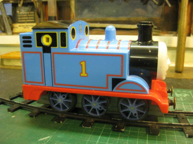
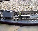
Over the years I have made quite a few battery powered 16mm scale locomotives. As I am about to start on another one I thought the forum might be interested to see some of my previous efforts. All have them have used inexpensive 1.5/3 volt 'Can' electric motors with a plastic worm and wheel drive to the axles.
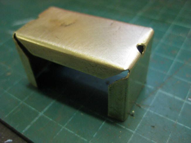
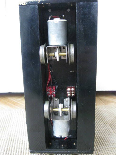
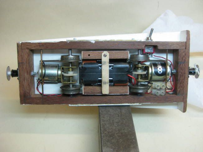
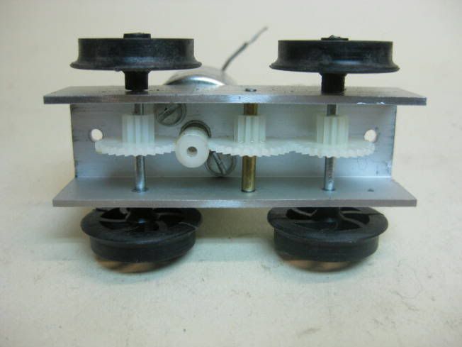
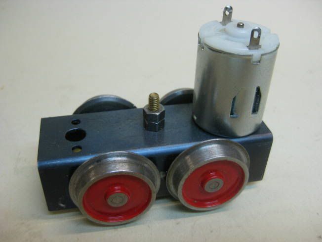
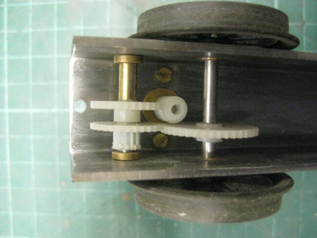
The first used brass or tin sheet bent up to hold the motor gears and axle. With K&S brass tube as gear spacers and Brandbright 1/8" steped bushes. This is a twin motor design where the motors can be run either in series or parallel as a simple speed control
This chassis is similar but has outside bearing so the motors are axle hung.
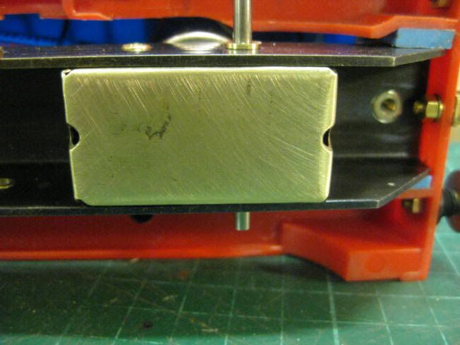
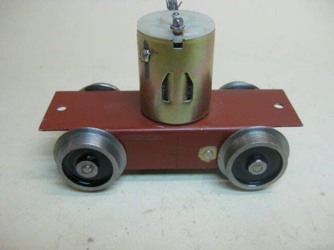
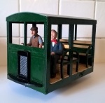
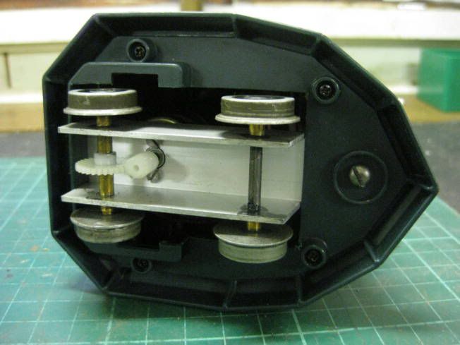
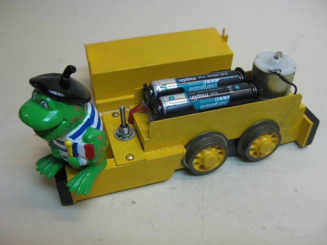
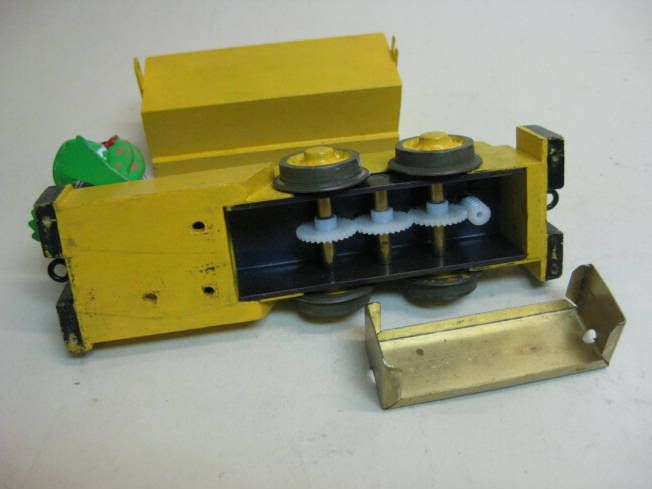
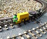
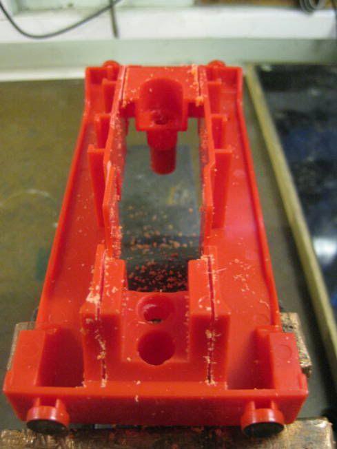
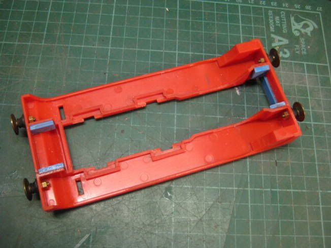
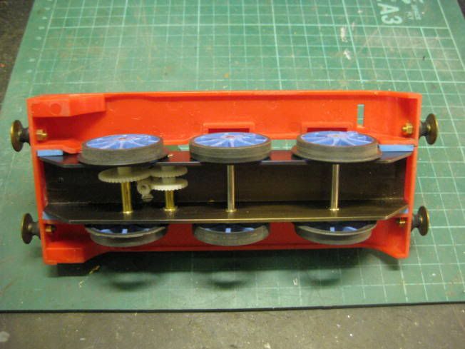
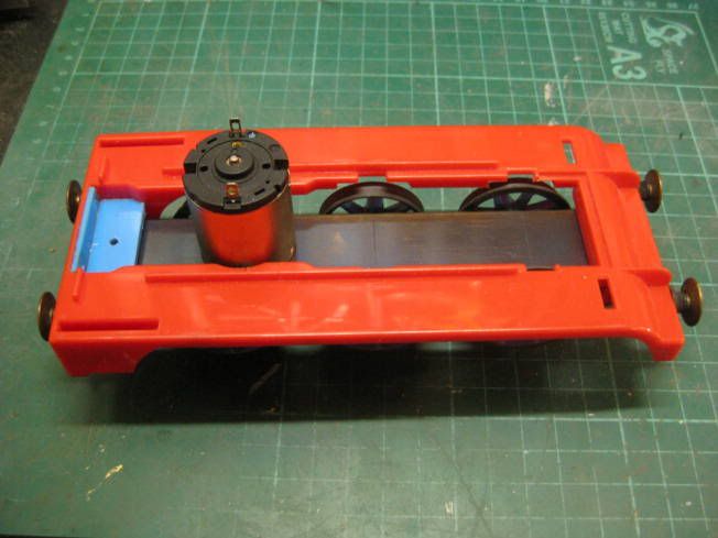
When IPE moved factories a few years ago a lot of their bits and pieces were sold off at the Llanfair show and along with other stuff a couple of their battery electric chassis were bought. The photograph shows one that was used on their Simplex 'Caravan' locomotive which has had brass bearings fitted which was part of the bits included in the stuff purchased.
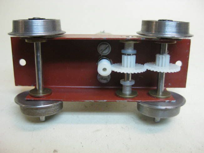
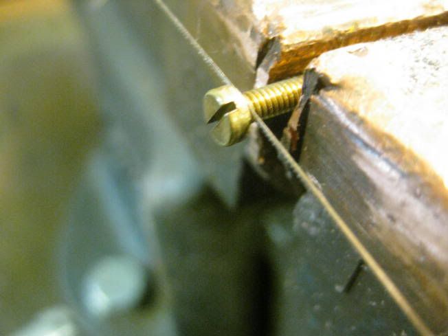
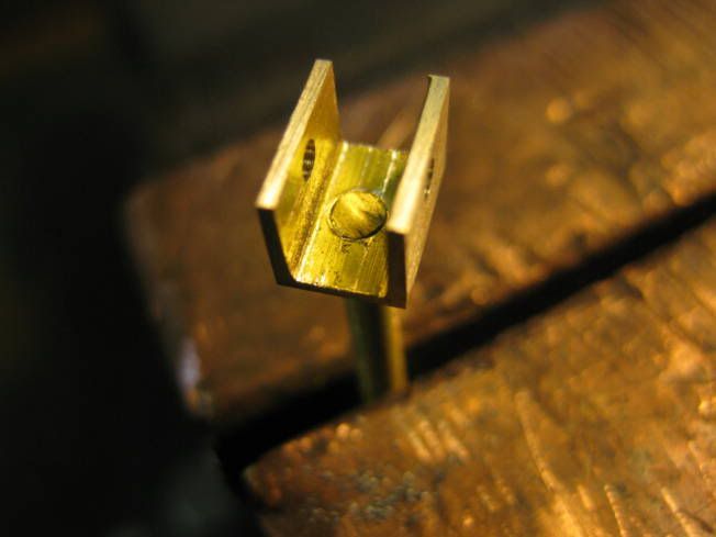
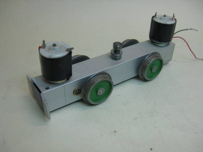
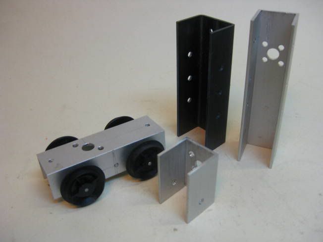
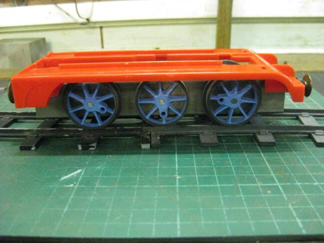
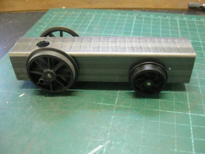
Having seen Ivan's neat construction further battery electric chassis made used his channel section idea. The channel used was either 20mm aluminium or 25mm square tube section steel which was made into channel. Both the aluminium and the steel were bought at B&Q. One of the first chassis made was very similar to IPE's product but 4WD and used aluminuim channel.
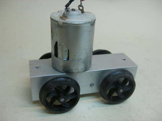
Another twin motor one using aluminium channel.
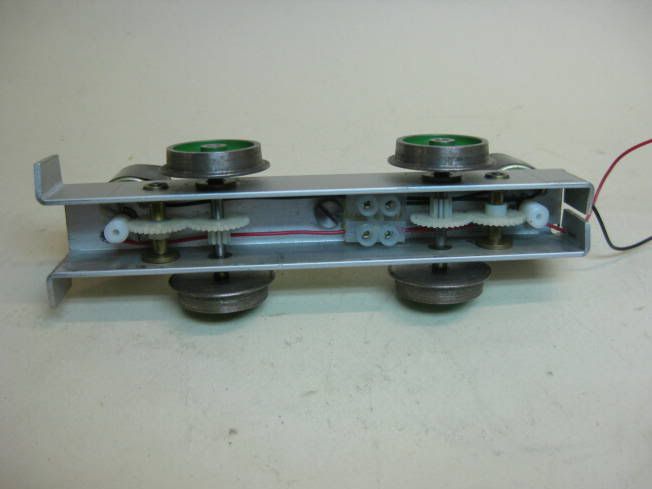
Another aluminium channel chassis using a sprokets and chain to give 4WD
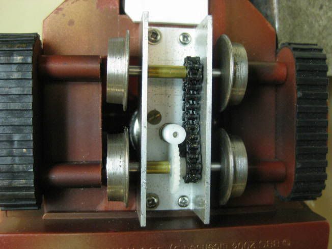
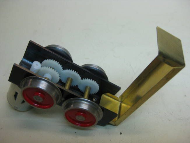
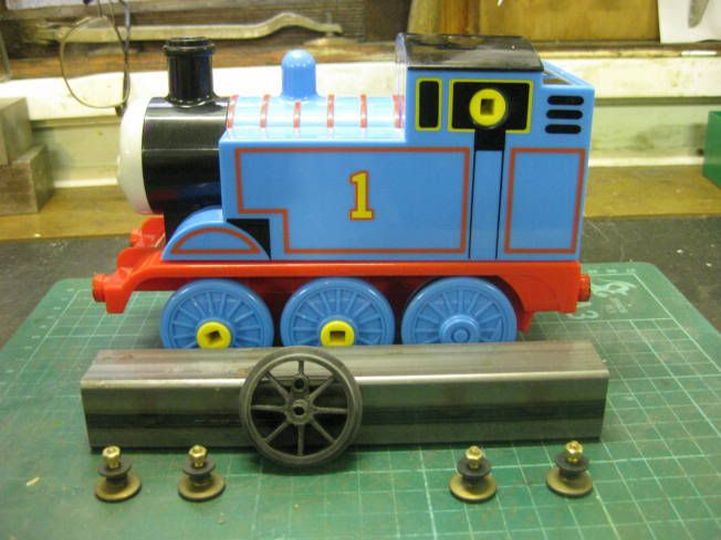
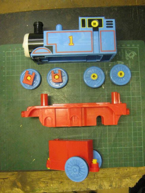
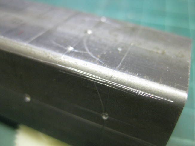
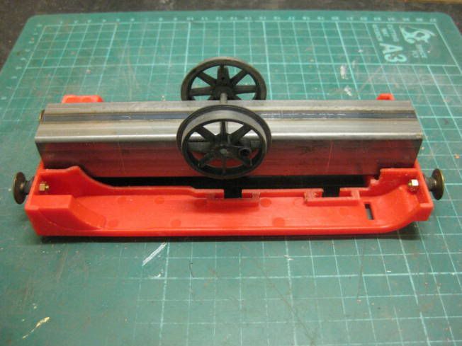
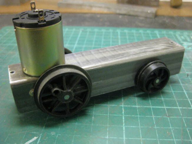
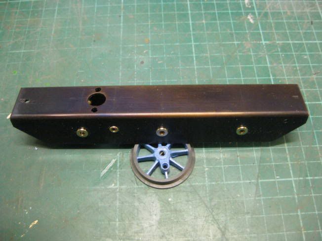
When a heavier more robust chassis was needed the 25mm steel square section tube is used. The photograph shows a power bogie that can be fitted with either one or two motors. This single motor version has 4WD and protection for the gears.
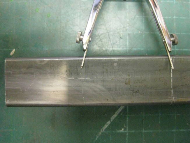
After many hours of running it has been found that the aluminium channel doesn't really need brass bearings fitted. A 25mm aluminium channel which was about 2mm thick would be ideal for making chassis. If the forum is interested I could take some photographs of the construction of the chassis just started and post them.
Regards Tony.


 .
.