Re: A Wickham trolley
Posted: Fri Apr 09, 2021 11:11 am
So far so good and much as I had expected, but now for the bits that I didn't quite know what to do with - the sockets, the fuse, the switch and the voltage regulator.
In my box of bits I found a small Voltage Reg module which was by chance exactly 15mm wide and fitted perfectly on top of the top frame spacer over the motor, held in place by piece of double sided tape.
The voltage regulator is essential because the battery is nominally 7.4v and the motor is only 3 volts. The original article suggested using a string of diodes to drop the voltage, but apart from being a messy waste of space, it simply doesn't seem the right way to go about it, plus of course the regulator will compensate for battery voltage dropping.
The battery balance charge plug on a short lead will wrap down the side of the gearbox frame out of the way inside the outer housing, so thats not a problem.
This leaves the main charge socket, switch and fuse needng homes. The Rx board is 35mm long and between the frame spacers under the battery pack there is a space about 53mm long, which leaves me with about 18mm spare, just enough for the socket mounted vertically. Half an hour later and I had printed an L-shaped replacement spacer with a hole in it for the socket. I had to bend the socket tags down level with it's body to leave room for the battery on top and this leaves a small gap behind the socket is just big enough for the auto reset fuse!
All that just leaves the on/off switch. Of course sometimes it's unavoidable, but I hate seeing switches visibly mounted on external frames, footplates, etc. In this case there isn't even that much luxury and I've been contemplating having to surface mount it and try to disguise it as a toolbox or something. The trouble with that is that it would have the switch mounted on the body not the underframe with all the electrics.
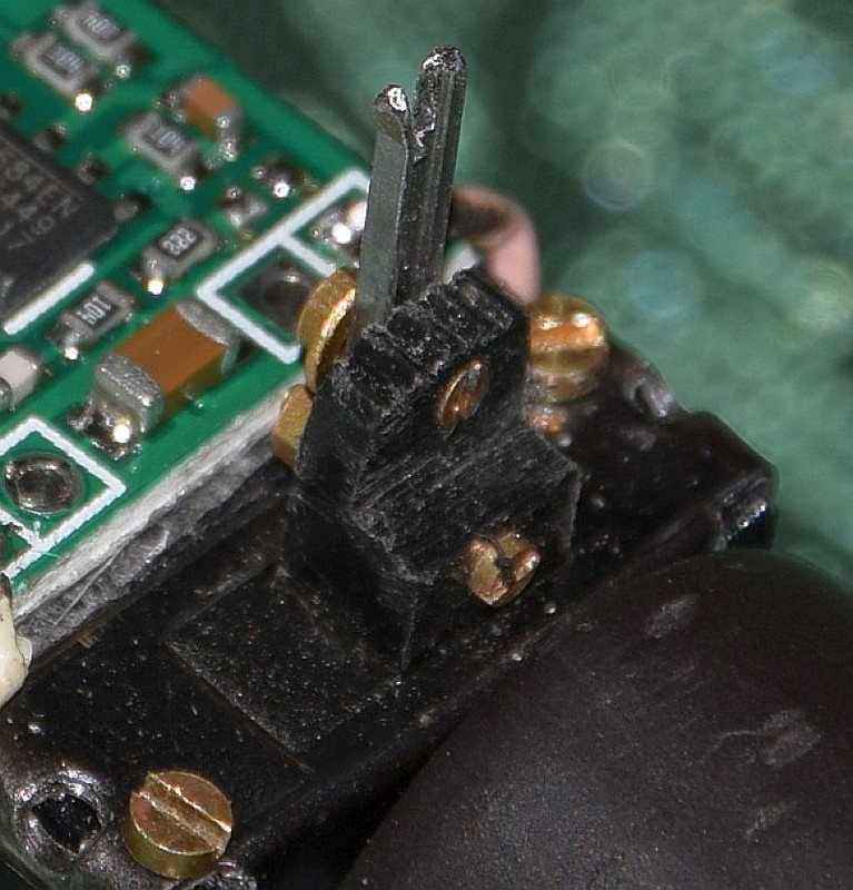
Then good fortune smiled on me again. In the photos, some of this early design of Trolley had a gap in the top boarding of the engine housing, just in front of the drivers seat. I'm not sure what it is for in the real thing, but there is a lever of some sort protruding up from it, gear lever perhaps? I had already left this gap when I printed the body parts and when I looked through this gap, after offering the works up underneath, low and behold there was a gap between the motor and the L-shaped spacer, which lined up almost perfectly with my top gap. Moreover, when I measured the actual space I found that a few strokes of a file could reduce the body of a slide switch slightly to fit between the frames. The switch knob was not quite lined up, but I sawed down from the top and reduced the width by about 50% so that it now slides in the gap. A little bit of work with a short piece of 4mm scale bullhead rail and a couple of 14BA nuts and bolts, gives me a 'knob extension' which allows the switch to function from above the body whilst being fixed to the works.
In my box of bits I found a small Voltage Reg module which was by chance exactly 15mm wide and fitted perfectly on top of the top frame spacer over the motor, held in place by piece of double sided tape.
The voltage regulator is essential because the battery is nominally 7.4v and the motor is only 3 volts. The original article suggested using a string of diodes to drop the voltage, but apart from being a messy waste of space, it simply doesn't seem the right way to go about it, plus of course the regulator will compensate for battery voltage dropping.
The battery balance charge plug on a short lead will wrap down the side of the gearbox frame out of the way inside the outer housing, so thats not a problem.
This leaves the main charge socket, switch and fuse needng homes. The Rx board is 35mm long and between the frame spacers under the battery pack there is a space about 53mm long, which leaves me with about 18mm spare, just enough for the socket mounted vertically. Half an hour later and I had printed an L-shaped replacement spacer with a hole in it for the socket. I had to bend the socket tags down level with it's body to leave room for the battery on top and this leaves a small gap behind the socket is just big enough for the auto reset fuse!
All that just leaves the on/off switch. Of course sometimes it's unavoidable, but I hate seeing switches visibly mounted on external frames, footplates, etc. In this case there isn't even that much luxury and I've been contemplating having to surface mount it and try to disguise it as a toolbox or something. The trouble with that is that it would have the switch mounted on the body not the underframe with all the electrics.
Then good fortune smiled on me again. In the photos, some of this early design of Trolley had a gap in the top boarding of the engine housing, just in front of the drivers seat. I'm not sure what it is for in the real thing, but there is a lever of some sort protruding up from it, gear lever perhaps? I had already left this gap when I printed the body parts and when I looked through this gap, after offering the works up underneath, low and behold there was a gap between the motor and the L-shaped spacer, which lined up almost perfectly with my top gap. Moreover, when I measured the actual space I found that a few strokes of a file could reduce the body of a slide switch slightly to fit between the frames. The switch knob was not quite lined up, but I sawed down from the top and reduced the width by about 50% so that it now slides in the gap. A little bit of work with a short piece of 4mm scale bullhead rail and a couple of 14BA nuts and bolts, gives me a 'knob extension' which allows the switch to function from above the body whilst being fixed to the works.