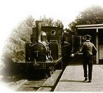
That track layout is specific to the way the Festiniog Railway marshalled its trains in the 1870's.
You need to know that goods wagons were placed next to the loco. Between the loco and the coaches. They were also in the habit of adding long rakes of empty slate wagons on the end of trains. Forget slate wagons for now. You also need to be reminded that this railway is at a constant gradient (1 in 80 if I remember correctly). That leads to this layout and the way Tan-y-Bwlch was operated.
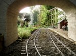
So looking at the last photo with the footbridge in the middle and the station house beyond it. The far track next to the mock wall up to the garden is the down line. The middle line closest to the viewpoint is the up-line, which crosses under the bridge and becomes the near outside line by the station building. So up trains drove into this up-line and the coaches remain below the crossover. The goods wagons inevitably are above the bridge and on the crossing. The train is split at the junction between goods and coaches, and the loco then draws the goods wagons forward over the top point, the point is changed, and the goods wagons are shunted into the middle road above the footbridge. There is a "scotch" locked in the rail which prevents the goods wagons rolling back down the slope and fouling the crossing. The goods wagons to be left at this station are the last goods wagons in the rake, and are uncoupled, and left here. The loco rejoins its coaches, and the goods wagons for higher up the line, and the coaches continue on their way. When the train has gone the scotch is unlocked, removed, and the goods wagons descend under gravity into the outer loop below the footbridge - which is where the goods shed is located. The goods shed has two doors, one uphill, and one downhill, so the goods wagons descend into the goods shed through the uphill door. When unloaded (or perhaps loaded with produce from the Estate which was very active in this period) they are ready to join a down train. So a down train is on the far track which does not go through the crossover. The loco is detached from the train, runs forward beyond the point and stops. The goods wagons descend under gravity, through the point, until they meet the loco. The loco and wagons are then backed onto the train, recouped, and sent away to Porthmadog.
That is my understanding of how this was worked and as such "explains" the track layout. Although I can't see why the same could not be achieved without the crossover - just using 3 parallel roads.
The reference for that peculiar layout is in "The "Festiniog Railway The Spooner Era and After" by Peter Johnson. It is also mentioned in Boydes book on the Festiniog - but the goods shed is in the wrong place in his diagram. That is what fooled me for a while.
Anyway I think you will understand why I had to build it like this - I look forward to seeing if I can actually shunt goods wagons in to the goods shed under gravity!
Trevor
The Railway in the Valley of the Mill
-
Trevor Thompson
- Trainee Driver

- Posts: 978
- Joined: Fri Oct 05, 2018 6:30 pm
- Location: South West Wales
-
Trevor Thompson
- Trainee Driver
- Posts: 978
- Joined: Fri Oct 05, 2018 6:30 pm
- Location: South West Wales
Re: The Railway in the Valley of the Mill
I have now laid the track bed all the way to the void. The last section involved a stone embankment which I plan to cover with soil and eventually grass. It is getting high enough, as the ground falls away to make me think about changing my technique for making the trackbed.
So here is the latest with both ends drawing up to the remaining half circle to be constructed over a fairly steep slope:
It looks like it is crying out to have an North American style wooden trestle viaduct. Not my first choice. The research I carried out looking at prototypes in the UK led me to Brunels Cornish viaducts, the Welsh river crossing viaducts at Barmouth and Loughor, and the slate mine one at Blaenau Ffestiniog.
The ones that are high and long are all wooden structures mounted on top of stone piers. The wooden supports radiate out from the stonework, to support the top deck.
I really don't want to have to cast concrete piers here. Providing a foundation which would stabilise a tall pier has put me off. Each pier would be different - some short and some tall - but no two the same. Making this accurately, on a curve, with a 1 in 80 slope, seems too difficult. I also want to have a result sooner than later, and I think casting piers would take a long time - and use a lot of wood for shuttering. I have worked out a way that I can set out the curve and slope and actually make fit if I do it this way:
So, much against my instincts it will be an North American style trestle viaduct.
How to set this out and make it accurately?
I am going to make it in stages, 3 trestles at a time, so I have made four sections of mock top deck and cut the ends at the correct angle to make them follow a 4ft 6inch curve when joined together. An extra length at the left allows it to be cantilevered of the last bit of concrete track bed. It can be seen in place in the photo. Two uprights clamped onto it allow me to set it at the correct slope and level it across the deck. So that lets me look down and see where the concrete foundations should be made. I made three sets of shuttering for the foundations and set then below the deck joints. The small concrete bases to support the bottom of each trestle can be seen in their shuttering on the right hand side of the photograph.
On the basis that each trestle will have the same profile, with the outer legs protruding at the same angle, and the longer it is the wider the base, I have made a template to create the trestles:
So while it is raining, and the concrete curing I can make three trestles. Since my temporary top deck is defining where the trestles will go I can measure their height from the concrete to the level of the trackbed. Just have to remember to take off the height of the real top deck and I know how long the trestle has to be.
The outline is in pencil. By marking the length of each trestle on the template I think I can then make each trestle to fit the specific place it is intended to fit into.
So off to make trestles!
Trevor
So here is the latest with both ends drawing up to the remaining half circle to be constructed over a fairly steep slope:
- IMG_1721.jpg (3.12 MiB) Viewed 3444 times
The ones that are high and long are all wooden structures mounted on top of stone piers. The wooden supports radiate out from the stonework, to support the top deck.
I really don't want to have to cast concrete piers here. Providing a foundation which would stabilise a tall pier has put me off. Each pier would be different - some short and some tall - but no two the same. Making this accurately, on a curve, with a 1 in 80 slope, seems too difficult. I also want to have a result sooner than later, and I think casting piers would take a long time - and use a lot of wood for shuttering. I have worked out a way that I can set out the curve and slope and actually make fit if I do it this way:
So, much against my instincts it will be an North American style trestle viaduct.
How to set this out and make it accurately?
I am going to make it in stages, 3 trestles at a time, so I have made four sections of mock top deck and cut the ends at the correct angle to make them follow a 4ft 6inch curve when joined together. An extra length at the left allows it to be cantilevered of the last bit of concrete track bed. It can be seen in place in the photo. Two uprights clamped onto it allow me to set it at the correct slope and level it across the deck. So that lets me look down and see where the concrete foundations should be made. I made three sets of shuttering for the foundations and set then below the deck joints. The small concrete bases to support the bottom of each trestle can be seen in their shuttering on the right hand side of the photograph.
On the basis that each trestle will have the same profile, with the outer legs protruding at the same angle, and the longer it is the wider the base, I have made a template to create the trestles:
So while it is raining, and the concrete curing I can make three trestles. Since my temporary top deck is defining where the trestles will go I can measure their height from the concrete to the level of the trackbed. Just have to remember to take off the height of the real top deck and I know how long the trestle has to be.
- IMG_1723.jpg (1.41 MiB) Viewed 3444 times
So off to make trestles!
Trevor
-
Trevor Thompson
- Trainee Driver
- Posts: 978
- Joined: Fri Oct 05, 2018 6:30 pm
- Location: South West Wales
Re: The Railway in the Valley of the Mill
The first three trestles have been made:
and this morning they have been fitted into position:
The template which defines the track bed is really useful. It allowed me to place the shuttering in roughly the right place, and when fitting the trestles allowed me to identify if they were the correct length, and in the correct position. One of them was too long - so I had to modify it but at least it was too long not too short.
I have the same amount of packing between the top of each trestle and the template so they must be the correct length. I am slowly adding the cross bracing between the trestles, limited by the number of small clamps that I have. Each trestle is glued onto the concrete using an expanding polyurethane glue. That should not only hold it in place but form a water proof layer between concrete and wood.
I think this is going to provide a strong lightweight method of getting around the loop. I know the wood will have a limited lifespan - but if the wooden sleepers I use are anything to go by it might last for quite a while. We will see! At least I can claim that it is a prototypical method of solving this problem, a temporary solution which can be replaced with something more permanent later.
The interesting part is going to be trying to make the two ends meet without a kink and without an abrupt difference in height. So far the plan is to add extra sections to the template when the ends get near enough for a template to span the gap.
Trevor
- IMG_1725.jpg (1.71 MiB) Viewed 3386 times
- IMG_1726.jpg (3.26 MiB) Viewed 3386 times
I have the same amount of packing between the top of each trestle and the template so they must be the correct length. I am slowly adding the cross bracing between the trestles, limited by the number of small clamps that I have. Each trestle is glued onto the concrete using an expanding polyurethane glue. That should not only hold it in place but form a water proof layer between concrete and wood.
I think this is going to provide a strong lightweight method of getting around the loop. I know the wood will have a limited lifespan - but if the wooden sleepers I use are anything to go by it might last for quite a while. We will see! At least I can claim that it is a prototypical method of solving this problem, a temporary solution which can be replaced with something more permanent later.
The interesting part is going to be trying to make the two ends meet without a kink and without an abrupt difference in height. So far the plan is to add extra sections to the template when the ends get near enough for a template to span the gap.
Trevor

Re: The Railway in the Valley of the Mill
That's going to be one heck of a big structure, Trevor. All the more complicated by being laid on a slope and on a curve. Very impressed with what you've done so far. Brunel would be proud of you ...... 
Rik
Rik
-
gregh
- Trainee Driver
- Posts: 571
- Joined: Sun Apr 01, 2018 5:44 am
- Location: Sydney, Australia
- Contact:
Re: The Railway in the Valley of the Mill
Thanks for the nicely detail description of your construction methods. I know how hard it is to lay out a 'circle in the air' - your method seems a very 'easy' method which should give a great result. I think your selection of a trestle was really the only way. Brunel's timber bridges, while looking beautiful, were for longer, straight spans
Greg from downunder.
The Sandstone & Termite's website: https://members.optusnet.com.au/satr/satr.htm
The Sandstone & Termite's website: https://members.optusnet.com.au/satr/satr.htm
-
Trevor Thompson
- Trainee Driver
- Posts: 978
- Joined: Fri Oct 05, 2018 6:30 pm
- Location: South West Wales
Re: The Railway in the Valley of the Mill
The plan is working so far. It is going to be a large structure as Rick said. Thanks for the kind comments Gregh, I agree that there is no other way of tackling this.
I have laid out the next section this morning and prepared the ground. It is fitting into the available space, and it hasn't disappeared down into the buildings. What I have built seems really strong and stable. I think it will take about another 12 trestles to complete it. Just hope it lines up in 3 dimensions with the track bed at the other end, but looks as though its going to.
This mornings progress:
Trevor
I have laid out the next section this morning and prepared the ground. It is fitting into the available space, and it hasn't disappeared down into the buildings. What I have built seems really strong and stable. I think it will take about another 12 trestles to complete it. Just hope it lines up in 3 dimensions with the track bed at the other end, but looks as though its going to.
This mornings progress:
- IMG_1731.jpg (3.7 MiB) Viewed 3517 times


Re: The Railway in the Valley of the Mill
Very niceTrevor Thompson wrote: ↑Sat Sep 11, 2021 5:14 pm The plan is working so far. It is going to be a large structure as Rick said. Thanks for the kind comments Gregh, I agree that there is no other way of tackling this.
I have laid out the next section this morning and prepared the ground. It is fitting into the available space, and it hasn't disappeared down into the buildings. What I have built seems really strong and stable. I think it will take about another 12 trestles to complete it. Just hope it lines up in 3 dimensions with the track bed at the other end, but looks as though its going to.
This mornings progress:
IMG_1731.jpg
Trevor
-
Old Man Aaron

- Trainee Driver
- Posts: 808
- Joined: Wed Oct 19, 2016 11:08 am
- Location: Sunshine Coast QLD, Australia
Re: The Railway in the Valley of the Mill
Gonna be a hell of a run, when the line's done. Beautiful.
Regards,
Aaron - Scum Class Works
Aaron - Scum Class Works
Re: The Railway in the Valley of the Mill
Have you seen Greg's curved trestle? It is indeed a sight to behold!Trevor Thompson wrote: ↑Sat Sep 11, 2021 5:14 pm . ..... Thanks for the kind comments Gregh, I agree that there is no other way of tackling this.
Trevor
Rik

Re: The Railway in the Valley of the Mill
That's going to look lovely when it's done - and with a superb natural backdrop too...
I love how in the most recent picture you can't see the lower end on the line, so it just looks as though the trestle's striking out on its own and could go on forever...
I love how in the most recent picture you can't see the lower end on the line, so it just looks as though the trestle's striking out on its own and could go on forever...
-
Trevor Thompson
- Trainee Driver
- Posts: 978
- Joined: Fri Oct 05, 2018 6:30 pm
- Location: South West Wales
Re: The Railway in the Valley of the Mill
No I haven’t but I will look for it now.ge_rik wrote: ↑Sun Sep 12, 2021 4:21 pmHave you seen Greg's curved trestle? It is indeed a sight to behold!Trevor Thompson wrote: ↑Sat Sep 11, 2021 5:14 pm . ..... Thanks for the kind comments Gregh, I agree that there is no other way of tackling this.
Trevor


Rik
Thanks for alerting me!
Trevor
-
Trevor Thompson
- Trainee Driver
- Posts: 978
- Joined: Fri Oct 05, 2018 6:30 pm
- Location: South West Wales
Re: The Railway in the Valley of the Mill
So thanks to Greg for inadvertently helping me to solve the problem of completing my curve!
-
Trevor Thompson
- Trainee Driver
- Posts: 978
- Joined: Fri Oct 05, 2018 6:30 pm
- Location: South West Wales
Re: The Railway in the Valley of the Mill
The second section of the viaduct is now complete:
So that is 7 trestles in place and all crossbraced, and the track "bed" glued on.
That has enabled me to look at how the two ends are going to join up. I have set up the template onto the last complete section and set up a straight plank from the other end - to see how near they are both in vertical height and in meeting horizontally:
You can see that as far as vertical height is concerned the two ends are at about the right height to actually meet. However as far as the two curved sections actually meeting it isn't quite right. I have set the straight plank so it is in line as straight track from the end of the curved bit. I have added 2 straight sections into the template as the sections nearest the last trestle, and where the two meet I have a 6 inch (150mm) gap - sideways.
Trevor
- IMG_1741.jpg (3.84 MiB) Viewed 3288 times
That has enabled me to look at how the two ends are going to join up. I have set up the template onto the last complete section and set up a straight plank from the other end - to see how near they are both in vertical height and in meeting horizontally:
- IMG_1743.jpg (3.95 MiB) Viewed 3288 times
Trevor
-
Trevor Thompson
- Trainee Driver
- Posts: 978
- Joined: Fri Oct 05, 2018 6:30 pm
- Location: South West Wales
Re: The Railway in the Valley of the Mill
Cutting the 6 inches of one of the straight lengths at the trestle end now makes them join!!!! 
So just to think about the gradients, most of the concrete part of this area of the line rises at 1:60. When I got to the trestle viaduct I calculated the vertical height again and estimated the track length - which suggested the gradient should ease to 1:80. Having built the trestle viaduct to 1:80 it seems that the remaining straight section where the plank is should be 1:60. So it meets up, and is as good as I was ever going to get it.
Just another 8 trestles to go.
Trevor
- IMG_1745.jpg (3.9 MiB) Viewed 3288 times
Just another 8 trestles to go.
Trevor
-
Peter Butler

- Driver

- Posts: 5245
- Joined: Sun Sep 09, 2012 10:33 pm
- Location: West Wales
Re: The Railway in the Valley of the Mill
That is looking superb Trevor, just remember the safety netting!
The best things in life are free.... so why am I doing this?
Re: The Railway in the Valley of the Mill
Well done. Hats off, I had enough of a problem with doing something similar with a simple deck boards curved semi circle ona gradient!
Philip
-
Trevor Thompson
- Trainee Driver
- Posts: 978
- Joined: Fri Oct 05, 2018 6:30 pm
- Location: South West Wales
Re: The Railway in the Valley of the Mill
Yes it is very pleasing that the ends actually look like they will meet!
As far as safety nets go, and Peter has a valid point as there is potentially a 12 ft drop here, I have something in mind.
Looking at prototypes I have noticed that a common way of providing a walkway involves some sleepers being longer than normal, and a walkway laid on both sides, with handrails fixed to the ends of the long sleepers.
So my cunning plan involves every other sleeper being long enough to carry a wooden walkway. On the metal bridge further down the line I used wooden slats left over from a venetian blind to form the walkways. The same seems appropriate here. Last time I glued wooden coffee stirrers on top but this time it is so long I am tempted to just fix the slats on their own. I was a thinking of holes in the end of these long sleepers to take handrail uprights (stansions), and thread a fairly heavy brass wire through them, perhaps 1.5mm diameter. I think the walkway and the handrails should act as a safety net.
I am currently glueing my track down with that polyurethane glue before which I use so much of, and I will do the same on the viaduct in particular.
Trevor
Re: The Railway in the Valley of the Mill
Not a viaduct, but this prevents trains taking a dip in my pond. Brass model boat stanchions on every 3rd extended sleeper, piano wire for the rails and stainless steel fine gauge mesh for the walkways. Lollipop sticks only lasted a couple of years. The check rails are largely cosmetic, but may be a good idea on a curved structure.
- 2020 May Refurb.jpg (6.3 MiB) Viewed 3253 times
Phil
Sporadic Garden Railer who's inconsistencies know no bounds
My Line - https://gardenrails.org/forum/viewtopic ... 41&t=11077
Sporadic Garden Railer who's inconsistencies know no bounds
My Line - https://gardenrails.org/forum/viewtopic ... 41&t=11077
-
Trevor Thompson
- Trainee Driver
- Posts: 978
- Joined: Fri Oct 05, 2018 6:30 pm
- Location: South West Wales
Re: The Railway in the Valley of the Mill
Thank you - that is really helpful. I like those ideas.
I’m going to look for the model boat stanchions - I was really not looking forward to turning up so many of them.
Trevor
I’m going to look for the model boat stanchions - I was really not looking forward to turning up so many of them.
Trevor
Re: The Railway in the Valley of the Mill
Try Cornwall Model Boats. Not the easiest site to navigate because they list things by brand, but if you dig for long enough there is an amazing selection of stuff available.
Philip
Who is online
Users browsing this forum: No registered users and 2 guests