Page 1 of 1
Charge socket wiring
Posted: Fri May 15, 2020 10:58 am
by Tom85
Hi everyone, I'm currently building 2 locos (a PDF Fowler kit, and a scratchbuilt Bagnall 2-4-0), both of which will be powered by nimh batteries. I'd like to be able to charge the batteries in situ and have bought some 2.1 DC charge sockets to incorporate into the locos.
I'm using the IP engineering manual speed controller kit for both locos. Can anyone with more electrical know-how than me tell me where i should wire the charging socket into the circuit? Here's the wiring diagram supplied by IP engineering with the speed control kit. The charge socket has 3 terminals. Many thanks!

Re: Charge socket wiring
Posted: Fri May 15, 2020 12:41 pm
by ge_rik
My suggestion would be as shown here, assuming that it comes with a DPDT switch for on/off as shown in the diagram.
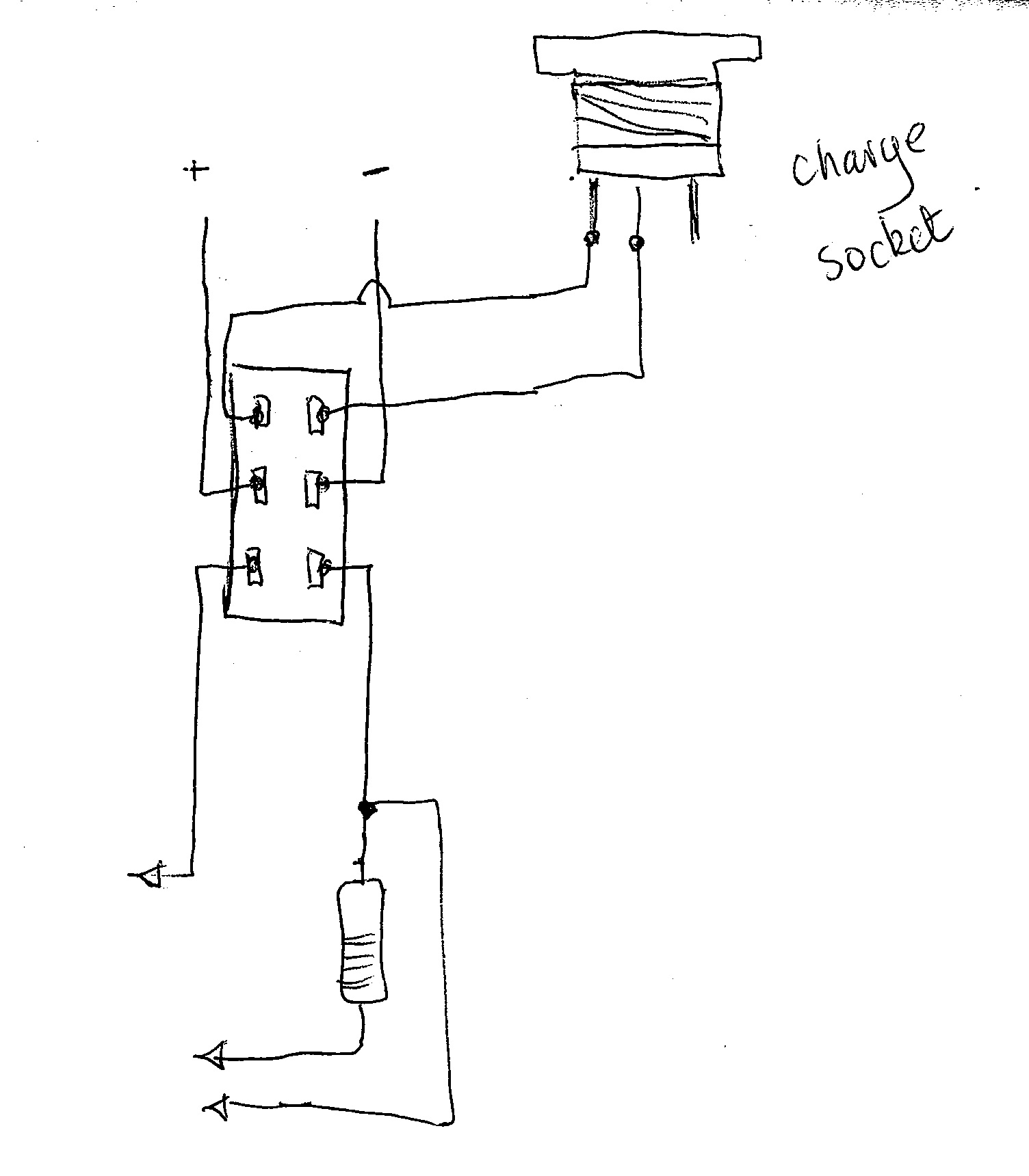
- charge socket.jpg (161.21 KiB) Viewed 3549 times
.
Rik
Re: Charge socket wiring
Posted: Fri May 15, 2020 3:05 pm
by Jimmyb
The three terminals are a conundrum for those that don't know, but one terminal goes to one input (the centre one I think) the other two, when the charging plug is not fitted connect to each other, and when the plug is fitted this connection is broke, and one connection goes to the charging socket, this is so in theory a DPDT centre off switch is not required (though I would always use one). You will require a meter of similar detector to determine which is which, with a plug inserted in the socket.
Re: Charge socket wiring
Posted: Fri May 15, 2020 5:34 pm
by ge_rik
If it's a standard DC socket, then the middle pin should be the neg connection. You should then be able to see which of the outer pins is riveted to the centre of the socket, which will be the pos connection. The other outer pin will be the switched neg output (ie connected to neg when no plug is inserted but open circuit (off) when a plug is inserted into the socket).
Hopefully that makes some sort of sense.
Rik
Re: Charge socket wiring
Posted: Fri May 15, 2020 10:10 pm
by Tom85
Thanks very much both! Will let you know how it goes. Cheers
Re: Charge socket wiring
Posted: Fri Dec 25, 2020 7:14 pm
by Phil.P
If you look at your charging socket from the rear (wiring side)..
Arrange it so the tags are left, right, and bottom..
Then:
The Right tag is Red (positive) - from the battery / charge - switch.
The Bottom tag is Black (negative) - from the battery.
The Left tag is the negative to your reversing switch / controller, etc. - I tend to use a 'geey' wire for this connection.
Being someone used to wiring, we call 'grey' 'slate'.
So to remember the above, we get :
Red - Right
Black - Bottom
sLate- Left
Works for me!
Phil. P