Does anyone know of a source for a drawing of the 0-8-0 and 2-8-2 DMs supplied to Sierra Leone Govt. Rlys. in the late 1950s by Hudswell? If so I would not mind seeing a copy, as I am 'revolving an idea.' The available photos on t'internet don't give much idea of size I am afraid.
On a related point - what's the chances of getting an eight coupled locomotive around a 5' radius bend?
Taa very much!
Peter in AZ
Sierra Leone Diesels
-
IrishPeter
- Driver

- Posts: 1400
- Joined: Wed Feb 23, 2011 3:24 am
- Location: 'Boro, VA
Sierra Leone Diesels
Traffic Pattern? What pattern? Spuds out; grain in, but cattle, sheep and passengers are a lot less predictable.
-
paullad1984

- Fireman

- Posts: 272
- Joined: Sat Mar 09, 2013 11:18 am
- Location: United Kingdom

Re: Sierra Leone Diesels
Probably not good, without making modifications of some sort. No flanges and wider treads on two driving axles would be the easiest to do, or maybe some form of side play on the driving axles.IrishPeter:119781 wrote: On a related point - what's the chances of getting an eight coupled locomotive around a 5' radius bend?
It's possible to draw it all out on paper, but my drafting skills aren't up to that, so I build a simple test model if I have doubts about the minimum radius capability of a planned new loco.
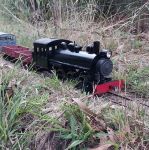
The attached pic. shows the test piece for a 2-6-2, made out of various ply offcuts from the wood scrap box. The test was necessary because I wanted flanges on all wheels and the original didn't have a trailing truck, just side play.

The front pony has the pivot in the right place as calculated by Baldry's Rule. the rear axle has side play only, what looks like a truck arm is just a rectangle of ply to stop the rear crosspiece from pivoting as it moves sideways.
The longitudinal piece is made the overall frame length of the model to give some idea of end overhang on curves.
The cross pieces have a 6mm step to simulate the wheel tread width and support the rig as it is slid along the track. The width of each cross piece depends on the points of intersection of the flanges and the rail, as this is the point where the flanges contact the rail on a curve and so limit the minimum curve that can be used.
Larger wheels need a wider cross piece, in this case the drivers are 45mm dia. and so the cross pieces are 18mm wide. The carrying wheels are 30mm dia. and the cross pieces are 12mm wide.
As it turned out the planned chassis will just squeeze around a 4' radius curve with all drivers flanged, but only with +/- 2.5mm sideplay on the trailing axle.
Regards,
Graeme
-
Tropic Blunder
- Trainee Fireman

- Posts: 189
- Joined: Sun Dec 06, 2015 4:02 am
- Location: Australia
- Contact:

-
Tropic Blunder
- Trainee Fireman
- Posts: 189
- Joined: Sun Dec 06, 2015 4:02 am
- Location: Australia
- Contact:
Who is online
Users browsing this forum: No registered users and 2 guests