Hi Dwayne,
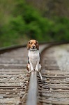
That rail bender is superb, it must make the job so much easier. Your geometry is really neat and the latest shots prove that very clearly. The whole railway looks good and it's really nice to see a train running on it.
By my reckoning your gradient works out at 1 in 27.
Keep the progress reports coming please!
Andrew
Norinoo Jct. Railway
-
Soar Valley Light

- Driver

- Posts: 1451
- Joined: Sun Dec 08, 2013 5:18 pm
- Location: North West Leicestershire

Thanks Andrew. A friend of mine made the railbender. It has proven to be an invaluable tool.
Just running the train around for a few minutes before dusk was fun. It allowed me the chance to see how operating sessions might transpire. Although I am building the layout with operations as a central theme, I hadn't put much thought into the actual process thus far as I simply concentrated on track building. The railway's customer base is still being mulled about in my mind as I hope to have some plausible sense of reason for trains once completely up and running.
Just running the train around for a few minutes before dusk was fun. It allowed me the chance to see how operating sessions might transpire. Although I am building the layout with operations as a central theme, I hadn't put much thought into the actual process thus far as I simply concentrated on track building. The railway's customer base is still being mulled about in my mind as I hope to have some plausible sense of reason for trains once completely up and running.


-
Soar Valley Light
- Driver
- Posts: 1451
- Joined: Sun Dec 08, 2013 5:18 pm
- Location: North West Leicestershire
Nice work again Dwayne.
How do you machine the rail down to form the switch blade? Do you put any 'set' (sideways joggle) in the stock rail to receive the blade?
I'm interested because I'm starting to think very seriously about my own turnout construction now. The angles, radii and length will dictate where I need to build the foundation so I need to get it right.
Andrew
"Smith! Why do you only come to work four days a week?
"'cause I can't manage on three gaffer!"
"'cause I can't manage on three gaffer!"
Thanks Andrew. I notch the stock rails to the rail web using nothing more than a small flat jewelers file. The stock rails are spiked down solid. I'll file the inside point railhead so wheel flanges don't pick them.
The most difficult aspect of building switches is that a third (or fourth) hand would come in handy when I begin the spiking process, starting with the frog and the tie it spikes down to as I use the same spike for the frog rail as I do the closure rails.
Another tip is that after I cut ties they all go into a bin with a lid and sprayed with water. This softens the ties to accept the nails I use as spikes. Ties not used stay in the covered bin where the humidity keeps them soft until the next spiking session. A nail set is handy for tapping in nails that encounter some resistance in the tie.
Here are a few photos of the current switch that I started yesterday and finished this evening.

For those who seem impressed by my work, thanks. But the reality is that they are anything but works of art. I post the photos to show that if I can build functional switches/points... then anyone can. I've got the basics down and my trains seem to run through them without any problems.
Anyways, a few close up photos of the frog and the points of the above switch.


Well, I think it's just that you don't see people laying their track by hand very often, and you seem to have hit upon a sleeper spacing, or something, that makes your track look very authentic.Dwayne:117090 wrote: For those who seem impressed by my work, thanks. But the reality is that they are anything but works of art. I post the photos to show that if I can build functional switches/points... then anyone can. I've got the basics down and my trains seem to run through them without any problems.
It's nice to see someone take the time to do it this way. Sometimes track needs a train on it in order to look nice, yours has that look that real narrow-gauge railways have, with an aesthetic appeal of its own even without the trains.
Thanks Keith. Achieving the narrow gauge look is what I was striving for and going to larger tie dimensions with this layout was an improvement in my opinion.
-----
Tonight I started work on the curved turnout for the passing siding at Hope.
First thing to do was determine the proper location for the switch.

Then cut out the section where the switch would go.

Do some test fitting and eyeballing for measurements before unspiking the existing rail.

And begin spiking rail to the ties.


That could be. I opted to increase tie length from 4.25" to 4.5". Along with their wider width the spacing of ties is about 2 feet (equal to the track gauge). The exception is that some of the ties of the switches are spaced at 1.5", particularly beneath the frog and the closure rails at the frog.LNR:117123 wrote:I think the extra sleeper(tie) length outside the rails is what accentuates the narrow gauge look, helped by the code 250 track. I believe many confuse restored tourist lines with the way track was laid in times past, with light rail and wide sleeper spacing.
As track work on the Norinoo Junction Railway continues the main objective is operations with the occasional run of the live steam engine. I envision the chance to do some switching at either Mags and/or Hope after work during weekdays and longer sessions on weekends when my busy schedule permits.
Schematically the NJRailway starts at Mags and terminates at Hope.
The end of track configuration at Mags should provide a couple of hours of switching opportunity.
At the Norinoo Junction switch a customer/freight house will be located on the mainline so that that switch can be used as a short siding (even though the main line continues towards Hope to make a loop for the benefit of running the live steam engine).
Continuing along there is the siding at Brendita where a still undetermined important customer will be located.
Just past Brendita is the abandoned siding and townsite of Inukshuk.
At Hope the planned passing loop will also have a siding coming off of it. Several customers will be located along the passing loop as well as the siding. Additionally those tracks will be able to be used as a 3-2-2 Inglenook puzzle for additional switching operations.
(schematic diagram below)

-
Soar Valley Light
- Driver
- Posts: 1451
- Joined: Sun Dec 08, 2013 5:18 pm
- Location: North West Leicestershire
Hi Dwayne,
Thanks for the detailed photos, I see much more clearly how you are building now. All the decisions you've made regarding spacing of timberwork make perfect sense and mirror 12" to the foot permanent way practise.
Your last post about operational arrangements was very interesting too. I'm in very much the same boat and planning to construct my line on very similar principles to ours. Like you, my main motivation is railway operation rather than locos. My line will be all steam but that is a secondary interest to operating a railway. I love the way your line will be shaped by the businesses that are developing along it.
Keep up the good work!
Andrew
"Smith! Why do you only come to work four days a week?
"'cause I can't manage on three gaffer!"
"'cause I can't manage on three gaffer!"
Thanks Andrew. The lack of operations on the previous layout is what bothered me the most about it and was the catalyst to start over. When James (LNR) suggested the passing siding at Mags, the option of having Mags being a point of operations in addition to Hope became the culmination of ideas.
I also drew inspiration from the Rik's Peckforton Light Railway as well as many other UK based layouts based on space limitations ya'll face. Something about the smaller layouts struck a cord with me along with how well many of these layouts blend in with the garden as opposed to having the garden somehow blend into the railroad. My goal is to have the railway "disappear" into my garden when it's all said and done.
I also drew inspiration from the Rik's Peckforton Light Railway as well as many other UK based layouts based on space limitations ya'll face. Something about the smaller layouts struck a cord with me along with how well many of these layouts blend in with the garden as opposed to having the garden somehow blend into the railroad. My goal is to have the railway "disappear" into my garden when it's all said and done.
If you don't mind me saying so, this has always seemed to me to be the difference between American and British garden railway practice. Americans typically seem to turn their gardens into big train sets, with the scenic elements sort of "plonked" into the middle of the lawn. It seems more typical in the UK to have the railway set into the background, which if you think about it is really what real railways are like.Dwayne:117133 wrote:Thanks Andrew. The lack of operations on the previous layout is what bothered me the most about it and was the catalyst to start over. When James (LNR) suggested the passing siding at Mags, the option of having Mags being a point of operations in addition to Hope became the culmination of ideas.
I also drew inspiration from the Rik's Peckforton Light Railway as well as many other UK based layouts based on space limitations ya'll face. Something about the smaller layouts struck a cord with me along with how well many of these layouts blend in with the garden as opposed to having the garden somehow blend into the railroad. My goal is to have the railway "disappear" into my garden when it's all said and done.
When I get around to building mine, I am going to have to have most of my track on a deck of some kind, because my "garden" doesn't really exist yet- it's just a flat gravel pad, and is rather small as well. I'm going to try to make my own track like you are doing- in fact your work has sealed my determination to do so- and I think I'm going to have to make my railway like a little seaside tramway or something. It's going to be a challenge to make it "blend in" with the scenery because the scenery will be entirely planted in boxes, with little viaducts connecting them (or something like that). Anyway, I think you're doing an very nice job indeed on your railway.
Did you make that rail-bender, or did you buy it? I need one!

Keith, the rail bender was made for me by a machinist I knew about seven years ago. We've since lost touch with each other unfortunately.
-----
KNO3, the ties are ripped from pressure treated fence pickets. The climate here in central Oklahoma tends to lean towards the dry side and when wood begins to rot, it's a long process. Having said that, as the plants I've planted begin to spread out and require routine watering, the potential for decay may become more of an issue. If this occurs, I'll simply have to do what the real railroads do... replace ties as they reach the end of their service life. Good excuse to have a MOW train.
Today I completed and installed the curved switch that will be located at the south end of the passing siding at Hope...


Next was to make the siding itself...

And then move on to the north end to install the switch I made a few days ago. I cut out a segment of the mainline and dropped the switch into place...

With those two switches in place all that remains is switch #3...

Switch #3 under construction which should be completed and installed tomorrow...

Who is online
Users browsing this forum: No registered users and 14 guests