AGNES / PERDITA

A place for discussing battery-electric locomotives, whether they're diesel, steam or even electric outline
MDLR

Post by MDLR » Fri Jul 30, 2010 3:14 pm

28th July

Image

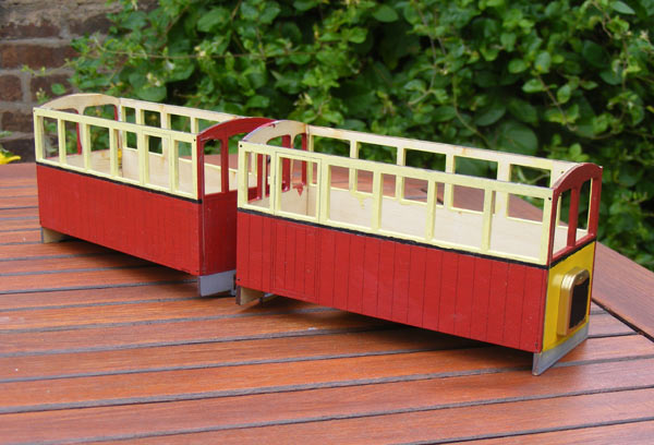
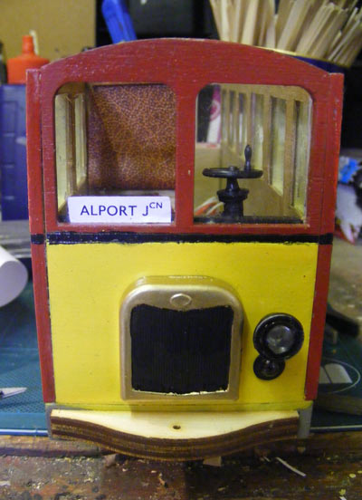
The final livery.........

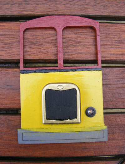
Off work – I’ve got a left knee that’s swollen up like a balloon and I can barely put weight on it, but I can sit down……….. I finally got all the exterior painting done, so now the sides and ends are ready for varnish. Looked out the headlights and got the interiors painted silver, ready to fit the LEDs. After a lot of very gentle drilling and opening out of holes 0.5mm at a time (to 6.5mm, if you really MUST know) I installed the bezels for the rear lamps and pushed the LEDs in from the back so these are ready for wiring up.
Image

29th July

<Facebook>
Brian is a fan of Acrylic Varnish – Become a fan
</Facebook>

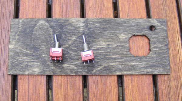
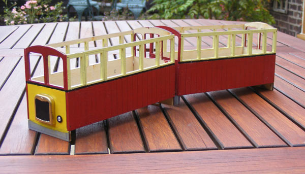
I actually varnished all the body panels last thing last night, so this morning, there they were, all nice and glossy and ready to assemble. Before that, I got out the two floors and drilled holes in them for the switches (6.5 mm again) – one single pole ON/OFF/ON switch for the directional lights (interior lights will work off the battery box switch) and one double-pole ditto for traction. I’m going to have to remember to switch them both in operation!
Image

Image

Image

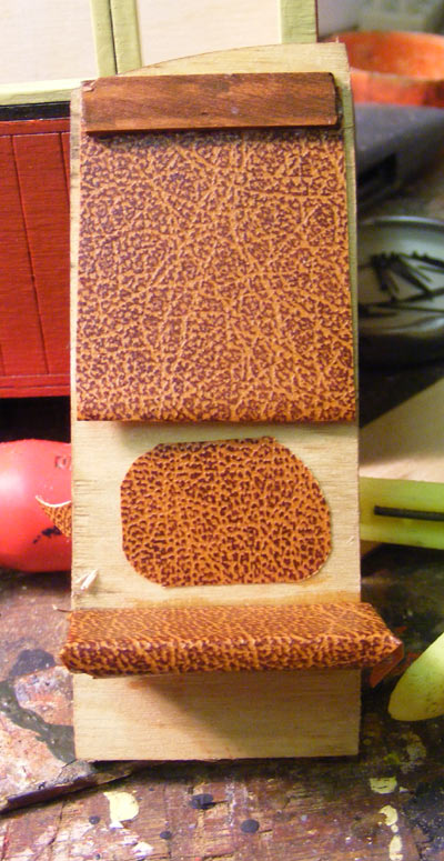
Once the cars were together, a number of anomalies reared their ugly little heads. On one side, both doors will be at the centre of the unit: on the other, they’ll be at the ends. This means that on one side of the unit, the name and number plates will be at the extreme ends – on the other side, they’ll be at the inner ends of each car, more-or-less next to each other. One end of the unit will drive from the left – the other end will drive from the right. Because I’ve opted for a half-width cab (I’ve cut down the full-width partitions, stained them and stained a piece of 1/8” square to act as a reinforcement on the cut edge) the seating arrangements have had to be altered. On the non-cab side I’ll be able to use the full-length seat Uncle Ivan so thoughtfully supplies, but behind the cab there’ll be a half-length seat behind the cab and a small seat behind the door. This means that there’s enough seating material left to make a Drivers’ seat. Most of the seats have been covered in the self-adhesive brown Rexine I bought for the job, which doesn’t seem to be as sticky as the green velour I bought for the Buffet Car, which means I’ve had to overlap it more.
Last edited by MDLR on Tue Nov 30, 2010 8:33 pm, edited 1 time in total.

User avatar
90733
Driver
Driver
Posts: 1955
Joined: Wed Dec 16, 2009 6:17 pm
Location: West Yorkshire
Contact:

Post by 90733 » Fri Jul 30, 2010 4:01 pm

Very Nice, your given me ideas now :roll: :D looking forward to seeing them finished.
Thanks
Jack

MDLR

Post by MDLR » Fri Jul 30, 2010 4:59 pm

30th July (again)

Second Spasm – Fun With Self-Adhesive Rexine

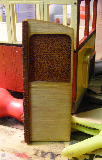
Having got the previous jobs written up, I went back to the workshop and finished covering the seats. I also made up the blinds for the back of the Driver’s cabs – an idea pinched from old buses and first-generation DMU’s. After fitting these (and representations of the boxes they were supposed to roll up into) I fitted the Driver’s seats. Next job? Lining panels!


Image

A cab bulkhead from the saloon side...............

Image

.......... and from the Driver's side!
Last edited by MDLR on Tue Nov 30, 2010 8:33 pm, edited 2 times in total.

User avatar
90733
Driver
Driver
Posts: 1955
Joined: Wed Dec 16, 2009 6:17 pm
Location: West Yorkshire
Contact:

Post by 90733 » Fri Jul 30, 2010 5:21 pm

Cool, looking good, you've tempted me to getting one, maybe at elsecar (i want to do one in my local bus colurs :D), looking forward to them finished, they look really awsome :D
Thanks
Jack

MDLR

Post by MDLR » Fri Jul 30, 2010 5:29 pm

Thanks for that. In actual fact, tarting them up isn't difficult - all you need is some imagination, some Cambrian Mouldings bits-and-pieces and a reasonable amount of materials like 0.8mm ply for the lining panels and coffee stirrers for all sorts of useful bits!

The hardest thing is imagining how you're going to alter them, working out the details as you go along (only sat down and looked at the seating today, fr'instance) and getting all the bits you need together, which is why I bought these at Stoneleigh but didn't start building them until earlier this month.

User avatar
90733
Driver
Driver
Posts: 1955
Joined: Wed Dec 16, 2009 6:17 pm
Location: West Yorkshire
Contact:

Post by 90733 » Fri Jul 30, 2010 5:40 pm

Ok, I will take that tip on board :D
Thanks
Jack

Narrow Minded

Post by Narrow Minded » Sat Jul 31, 2010 3:54 am

Looking very neat Brian - I like 'em!

Quick question, what paint have you used on the rad frames? It looks excellent!

MDLR

Post by MDLR » Sat Jul 31, 2010 12:42 pm

Narrow Minded wrote:Quick question, what paint have you used on the rad frames? It looks excellent!
I've actually used a can of Plasticote Brass finish spray paint. I'm not a fan of the stuff (I've heard too many horror stories about it going 'orribly wrong) but it's fine for this particular specialised application. The rads were sprayed with Plastic Primer spray paint first, just in case..........
Last edited by MDLR on Sat Jul 31, 2010 12:57 pm, edited 1 time in total.

MDLR

Post by MDLR » Sat Jul 31, 2010 12:42 pm

31st July

It’s odd how ideas suddenly occur……………. I’ve been debating about the motors Uncle Ivan supplies for the railbus (and other kits). His method of “laser a hole in the floor which the motor pushes into” is simple and works well, but in the case of the railbus you end up with a whacking great motor sticking up in the interior somewhere, which is one reason why it got swopped from the driving end to the inner end of each car. Even there, there would have been little or no room between the seats for (imaginary) passengers to get round it (or around the wooden case I was going to build around it).

I was mulling all of this over in my mind just after I woke up, when I had an “Eureka!” moment. I suddenly remembered that you can get flat (well, flattish) 3 volt motors – Brian Clarke often used them in Saltford Models kits – and they’re not expensive! One of these could sit under the floor and be glued into position: perhaps not flat – there might need to be some sort of shim to tilt the motor so the gears mesh nicely, or the motor might need to be packed with some thin ply to achieve the same effect, but it shouldn’t be too difficult to end up with a motor totally out of the body, and I have the skills to be able to do it!

Having got back from Derby with LEDs for headlights and interior lighting, I dug out my Squires catalogue and found the motors, which are going to cost me a bank-account-breaking SEVENTY-FIVE PENCE EACH! A call to them got them whizzing on their way, so early next week I’ll be able to look at this in rather more detail. Meantime, there’s still plenty to do…………

Narrow Minded

Post by Narrow Minded » Sat Jul 31, 2010 4:56 pm

Thanks for the "heads up" on the brass spray Brian, I'll get some and give it a try :D

I wouldn't glue the motors directly to the railcar - wouldn't maintenance & possible replacement be made easier if you mount them onto thin ply, then screw / bolt this to the underframe?
(It's what I've done on the "Scratchbodge Railcar" :D )

MDLR

Post by MDLR » Sat Jul 31, 2010 6:11 pm

Narrow Minded wrote:I wouldn't glue the motors directly to the railcar - wouldn't maintenance & possible replacement be made easier if you mount them onto thin ply, then screw / bolt this to the underframe? (It's what I've done on the "Scratchbodge Railcar" :D )
It always seemed to work OK for Brian Clarke, and the motors are only 75p each, so "destructive maintenance" would be quite permissible in my view!

Narrow Minded

Post by Narrow Minded » Sat Jul 31, 2010 6:38 pm

"destructive maintenance" would be quite permissible in my view!
At 75p a throw, I wasn't thinking of the motor! - I was concerned for the railcar :? !!!!

MDLR

Post by MDLR » Sat Jul 31, 2010 9:57 pm

Second Spasm……………..

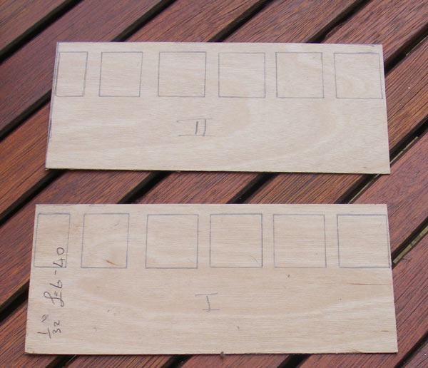
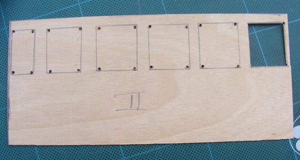
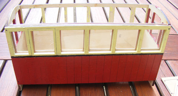
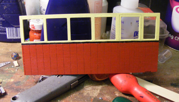
…………… which started out by making the internal lining panels for the sides of each railcar, from 1/32” ply I keep for the job. I've learnt from doing the Buffet Car………. Each panel is firstly cut to fit closely inside each side. Then, with a SHARP pencil I draw around each window and drill a hole inside each corner. These (in theory, at least) act as “stoppers” and stop the knife carrying on and slicing through the fragile window pillars. This doesn't always work: certainly not at the ends, where the internal pillars would only be about 1mm thick. All the cutting out is done with a Stanley knife with a new, sharp, blade: when I did the Buffet Car I used a scalpel and apart from damn near slicing my fingers to pieces, the pressure required on a slim handle to make a cut was ENORMOUS!

Image
Sides drawn out................

Image
............... holes drilled and cutting started...........

Image
................ and fitting in place with the glazing!

Once they were done, I attempted to cut out all the glazing. Unfortunately, the Wickes Acrylic Glass I bought for the job acts just like glass, and cracked and shattered where I didn't want it to. Fortunately, it's a big sheet…………….

I also added the bars that the glazing will sit on, to stop it sliding down and disappearing between the two layers of ply, and got the sides stained Light Oak – I'm going to glue all in place when I've finished writing this.

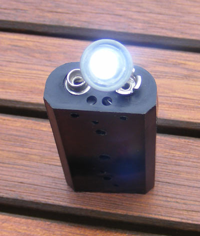
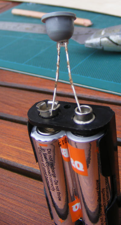
I've also assembled and painted the two front headlights from Cambrian Mouldings, having first drilled two small holes in the back of each one and epoxied a 3mm white LED in each one. They work a treat!

Image

The headlamp on test - in bright sunlight, let me add!

Image
This shows the depth of the headlight.
Last edited by MDLR on Tue Nov 30, 2010 8:35 pm, edited 1 time in total.

MDLR

Post by MDLR » Sun Aug 01, 2010 6:22 pm

1st August

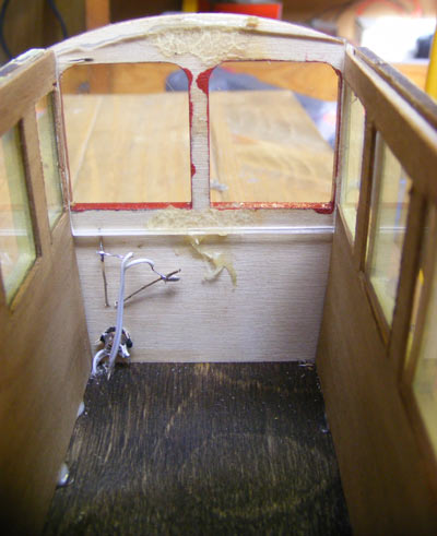
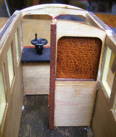
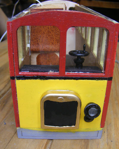
Only a small amount of progress today, and only on one car. The end glazing was fitted on the Driver's end of the car, the control desk was cut down (because now it needs to be smaller, because of the added glazing and lining) and stained and painted. The headlight was fitted and both headlight and tail lamp wired and tested (because they're going to be boxed in by the control desk). I broke the Cambrian Mouldings brake handles out of store and assembled and painted them, and drilled out the top of the control desk 5.5 mm to take the shaft of the brake column. Finally, the control desk was fixed in place and the half-bulkhead which creates the Driver's cab was glued in place. I was going to fit the seats, but I'm increasingly unhappy with the nonstickyness of the (alleged) self-adhesive rexine. It doesn't appear to like to stick to wood, so it's going to have to be secured in place with Evo-stik before the seats can be fitted.

Image
Lights wired and glazing fitted...........

Image
............ control desk and half bulkhead fitted...........

Image
............ and the view from the front end.
Last edited by MDLR on Tue Nov 30, 2010 8:36 pm, edited 1 time in total.

MDLR

Post by MDLR » Sun Aug 01, 2010 6:24 pm

Narrow Minded wrote:
"destructive maintenance" would be quite permissible in my view!
At 75p a throw, I wasn't thinking of the motor! - I was concerned for the railcar :? !!!!
I'll probably use something like Evo-stick to hold the motor in place - it can be made to "unstick" in a non-destructive way!

MDLR

Post by MDLR » Wed Aug 04, 2010 9:57 pm

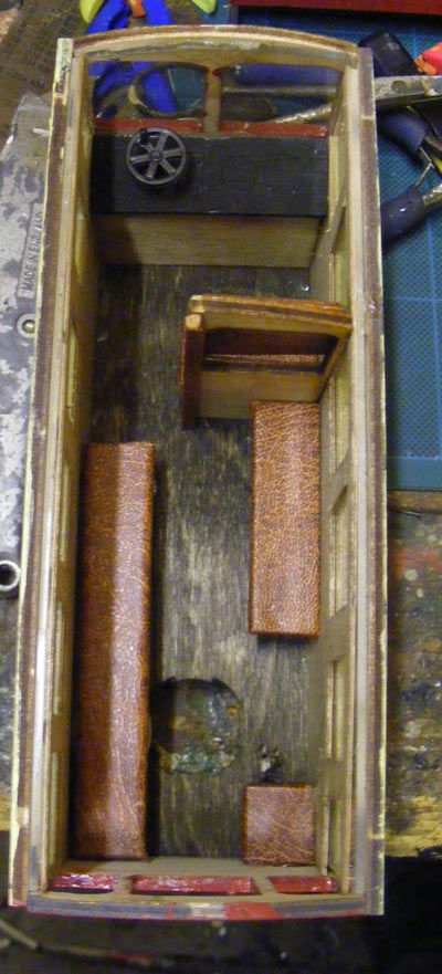
Image
Firstly, a view of the interior with the seats fitted (tho' one's not stuck down yet - access to switch).

4th August

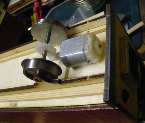
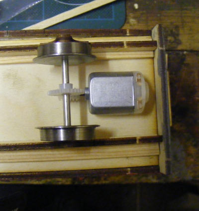
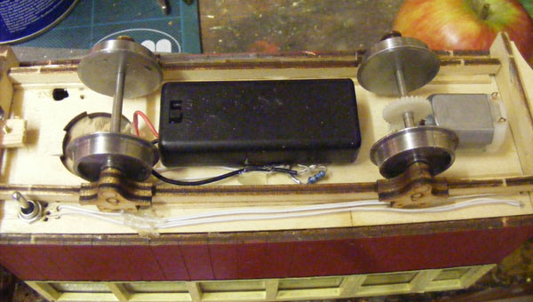
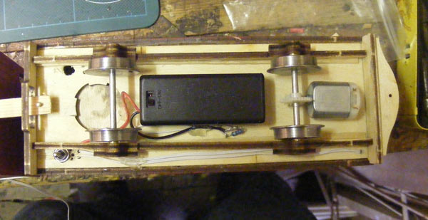
The new motors arrived from Squires today and though I'd been out all day for a non-railway function and was fairly knackered, I HAD to see how they were going to fit. Having fitted the gear to the axle and the worm to the motor, I offered everything up, roughly. To start with, the motor would have needed to be cocked up on end quite a bit to get the worm and the gear to mesh – in fact, the motor would have ended up perilously close to rail level. Then, I had an inspiration. Instead of tilting the motor to reach the gear, why not move the gear? Nothing could be simpler – a strip of wood between solebar and floor would make the cars ride a fraction higher, but will allow the motor to sit flat – in fact it may need slight packing with thin ply – Simples!

Image
The gears meshing perfectly.............

Image
............ and the motor sitting flat.
Last edited by MDLR on Tue Nov 30, 2010 8:37 pm, edited 1 time in total.

MDLR

Post by MDLR » Sun Aug 15, 2010 7:07 pm

15th August

“The Wheels on the (Rail)Bus go Round & Round…….”

In which a coupling is achieved, cherished ideas are abandoned, the perils of kit-bashing rear their ugly head and the MDLR has a Terence Cuneo Moment.

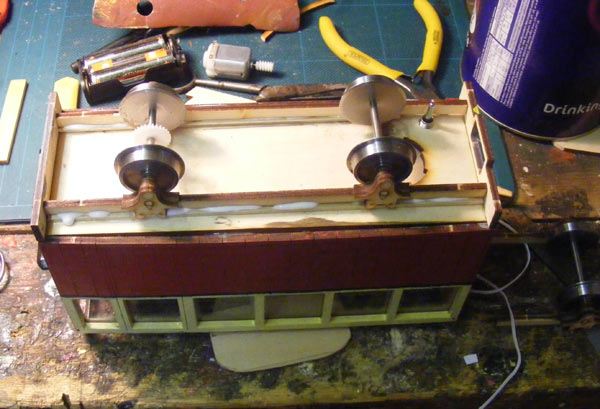
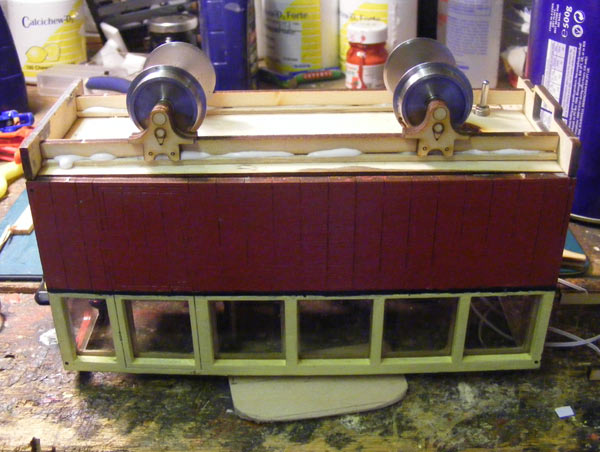
An early start today, after No 2 Son’s birthday bash last night. The extra lengths of wood on which the solebars will sit were sourced and fitted – not without difficulties, as wiring and switches tended to get in the way.

Image


Image


Whilst the glue on these was going off, the second set of solebars, bearings and axleboxes got assembled, as did the second driving axle. Once this was done, the MDLR had a Terence Cuneo Moment as “A Railbus is Wheeled” – all went together well. The second car followed in due course, following which a coupling was fabricated.


Image


Image

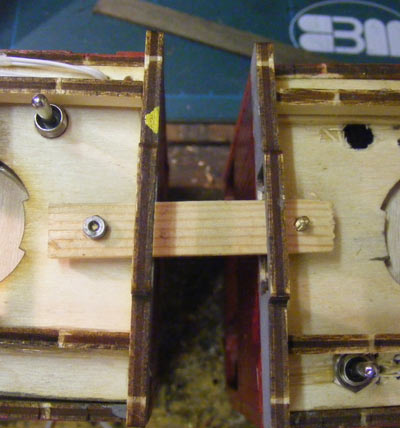
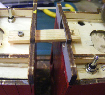
This is nothing more complicated than a pair of 8BA nuts and bolts, fitted through the floor at the rear end of each car, head end up. One of these carries a length of wood (with the nut superglued in place on the end of the bolt) – the other bolt is secured by a nut immediately below the floor. This gives a coupling which is easy to undo and reassemble, but means that the two cars will be able to travel side-by-side, taking up much less room than would otherwise be the case.

I’ve had to discard a couple of things that I was going to add to the set. I’d bought a set of horns (sheep and trespassers on the track for the warning of) but was disappointed by the results when they were assembled – the “trumpets” at the business end did not flare as well as I would have liked them to, and as they were to have been mounted in the ends, rather than on the roof, I didn’t consider them to be good enough, so out they went.

I’d also wanted to add destination boxes and displays and had already made up a “destination blind” with a few names on (once I’d remembered how to do white-on-black lettering on the computer) but found there wouldn’t have been room to incorporate these as I would have wanted. The fall-back position is to try Underground-style black on white destination plates in the driving end windows of each car – I’ve just printed these off and will try them when I go back to the workshop.

(a few minutes later)

They work – or at least they WILL work when I succeed in cutting them out neat and straight – thank goodness they’re the cheapest component of the whole build!


Image

I’ve also just fitted the “bumpers” which pass for buffer/couplings on the EeZee range, having glued the two layers of ply together earlier in the day. Here, another Peril of Kitbashing raised its head – I can’t put a coupling hook in either end because it fouls the new radiators which are thicker than the ply ones Uncle Ivan supplies! Never mind: they were never going to haul anything, anyway!


Image


Image

The motors glued in position - notice the wiring!
Last edited by MDLR on Tue Nov 30, 2010 8:39 pm, edited 1 time in total.

MDLR

Post by MDLR » Sun Aug 15, 2010 10:21 pm

Postscript:

I've just been out to the workshop and put a battery across each motor. They both worked OK after a little "persuasion" to start rotating, but the wheels went round at one hell of a rate: I get the feeling that the run from Youlgrave to Alport Junction may just be a quick one!

G'night!

MDLR

Post by MDLR » Mon Aug 16, 2010 9:12 pm

This morning I had a thought.................... If I run the batteries in parallel, instead of series, I should get a slower speed with a bit more OMPH - I'll only be using dry batteries, so the dire warnings about running rechargeables in parallel won't apply..........

I'll try it tomorrow night.............

MDLR

Post by MDLR » Sat Aug 21, 2010 7:15 pm

21st August

Today started yesterday, when I called into Potts to pick up some heatshrink to put round all the wires which pass between the two cars. Shame I didn’t pick up a couple of battery boxes, too………….

Today started (after another trip to Derby for battery boxes – the parking cost more than the boxes) with making up and installing the traction wiring. This was DEAD easy, because the switch which is the heart of the whole installation was out on the bench, so attaching and soldering all the wiring to it was an absolute cinch. I DO wish I’d done the lighting the same way…………

In due course, the switch was thrown and one motor operated in the right direction. THEN I tested and set the second motor’s connection, so both motors and sets of wheels went round in the SAME direction – most important, this! I needed to “tune” the motors by moving them slightly – the Evostick the motors were fixed down with let me do this. Turns out the gears were a LITTLE too tight and binding – twisting the motors slightly altered things from “bound solid” and making the usual grinding noises I associate with IP Engineering gears to silky smooth and almost silent!

After this, the wiring was all secured in place and I started in on the lighting. Now both cars are permanently connected together by the wiring for lighting and traction, so life’s become a little more challenging. Also, the lighting switch has been fitted, so had to be removed to attach the rest of the wiring to it. At the same time, I had to add an unswitched supply (apart from the switch on the battery box) for the saloon lighting, which is obviously not direction dependent. The wiring and lights in the “T” car were completed, as were the positive connections for the head and tail lamps, but when a wire snapped off just after I’d re-fitted the lighting switch I decided to take a break.

Post Reply

Who is online

Users browsing this forum: No registered users and 17 guests