Page 2 of 3
Re: Using OpenSCAD to produce drawings for 3D Printing
Posted: Sat Jan 01, 2022 4:05 pm
by -steves-
In Tinkercad for curved words I just use this, it's built in and simple to use.
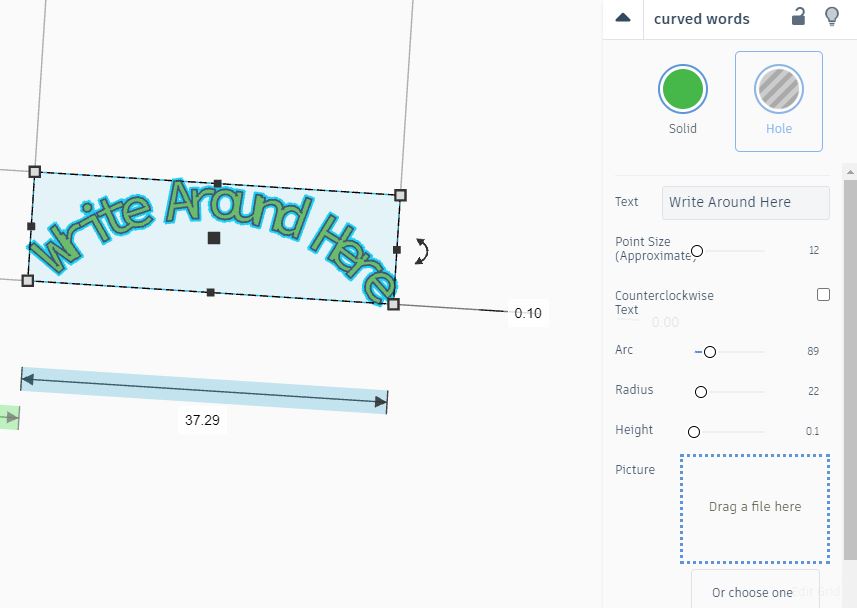
- delete.JPG (46.1 KiB) Viewed 5911 times
Re: Using OpenSCAD to produce drawings for 3D Printing
Posted: Sat Jan 01, 2022 4:54 pm
by SimonWood
ge_rik wrote: ↑Sat Jan 01, 2022 1:30 pm
Have you figured out a way of getting the flare at the base of a loco dome or chimney with OpenSCAD? It's one of the trickiest things to do in TinkerCAD and I've still not yet mastered it.
This is a great question. But not an easy one! Especially as I've never made a dome virtually or physically. I've had a look at the way you did it in TinkerCAD (cutting into a disc with a Taurus) and I guess physically you'd do it on a lathe (and a mill?) which seems like a good excuse to look at OpenSCAD's rotate_extrude() which is sort of like a virtual lathe... although the outcome is really just going to be the same as what you did in TinkerCAD, nothing more.
But out of curiosity...
If I draw a square and cut a circle out of it I get the shape I'm after (this is the 2D equivalent to cutting the torus out of the disc).
Code: Select all
difference(){
    square([3,3]);
    translate([0,3,0])
        circle(3);
}
$fn=100;

Now I rotate_extrude() it
Code: Select all
rotate_extrude()
    translate([-10,0,0])
            difference(){
                square([3,3]);
                translate([0,3,0])
                    circle(3);
            }
$fn=100;

And then if I want I can stick a dome inside it.
Code: Select all
dome();
module dome() {
cylinder(10,7,7);
translate([0,0,10])
    sphere(7);
flare();
}
module flare() {
rotate_extrude()
    translate([-10,0,0])
            difference(){
                square([3,3]);
                translate([0,3,0])
                    circle(3);
            }
}
$fn=100;

Still left with the problem of wrapping it round the boiler curve though...
-steves- wrote: ↑Sat Jan 01, 2022 4:05 pm
In Tinkercad for curved words I just use this, it's built in and simple to use.
Well that could have saved me a lot of work! (Although I'd have learned a lot less...) I looked for something like that - and couldn't find it - and indeed I still can't find it!
Re: Using OpenSCAD to produce drawings for 3D Printing
Posted: Sun Jan 02, 2022 9:36 am
by -steves-
The dome looks fantastic, however it's only good for a flat boiler. The dome for a round boiler needs the flare to change inline with the size of the curve of the boiler.
If you can do the code for that, it would be extremely useful, especially for those of us who struggle with any type of programming

Re: Using OpenSCAD to produce drawings for 3D Printing
Posted: Sun Jan 02, 2022 10:01 am
by SimonWood
-steves- wrote: ↑Sun Jan 02, 2022 9:36 am
The dome looks fantastic, however it's only good for a flat boiler. The dome for a round boiler needs the flare to change inline with the size of the curve of the boiler.
If you can do the code for that, it would be extremely useful, especially for those of us who struggle with any type of programming
This definitely has the feel of a 3 pipe problem…
I think there may be ways to do it… Googling suggests I need to understand how it handles minkowski() addition - I don’t - and there may be less computationally intensive ways to do it, but I probably need other OpenSCAD transformations and keywords I don’t know about. Which is why I’m enjoying the puzzle (especially as I have no need to print a dome!) I found an online book
Mastering OpenSCAD which is excellent (I’ve already identified errors in my techniques, and discovered things e.g. submodules that could make my ‘code’ much neater).
Re: Using OpenSCAD to produce drawings for 3D Printing
Posted: Sun Jan 02, 2022 10:28 am
by philipy
SimonWood wrote: ↑Sun Jan 02, 2022 10:01 am
-steves- wrote: ↑Sun Jan 02, 2022 9:36 am
The dome looks fantastic, however it's only good for a flat boiler. The dome for a round boiler needs the flare to change inline with the size of the curve of the boiler.
If you can do the code for that, it would be extremely useful, especially for those of us who struggle with any type of programming
This definitely has the feel of a 3 pipe problem…
I think there may be ways to do it… Googling suggests I need to understand how it handles minkowski() addition - I don’t - and there may be less computationally intensive ways to do it, but I probably need other OpenSCAD transformations and keywords I don’t know about. Which is why I’m enjoying the puzzle (especially as I have no need to print a dome!) I found an online book
Mastering OpenSCAD which is excellent (I’ve already identified errors in my techniques, and discovered things e.g. submodules that could make my ‘code’ much neater).
Cor blimey...my brain 'urts just reading wot you've rit, let alone trying to understand it!
Hats off to you though Simon.

Re: Using OpenSCAD to produce drawings for 3D Printing
Posted: Sun Jan 02, 2022 10:29 am
by SimonWood
This doesn't help with the dome problem... but I did find, in Mastering OpenSCAD, both the mirror transformation and a neat trick with a for loop that helps with symmetrical objects - such as my headboard above.
Take for example the cylinders I used for the cutouts in the headboard. I can take this piece of code, which basically involves a copy and paste job on the cylinder with 1 parameter changed for its reflected counterpart:
Code: Select all
//  How thick the board on which the lettering is placed should be
backboard_depth=2;
//  How high the letters should be
font_size=6;
//  The thickness of the letters above the board
lettering_depth=1;
//  The radius of arc forming the outer edge of the headboard
outer_radius=50;
//  How big the border around the edge of the board should be
border_width=1;
backboard_height=3*font_size+2*border_width;

rotate(-120/2)
    translate([0,outer_radius,-1])
        cylinder(backboard_depth+lettering_depth+2,backboard_height/2,backboard_height/2);
rotate(120/2)
    translate([0,outer_radius,-1])
        cylinder(backboard_depth+lettering_depth+2,backboard_height/2,backboard_height/2);

I can just use one instance of the code - and because if you give mirror() the zero vector as the direction to mirror in, it won't mirror - just use a for loop from 0 to 1 to draw both the original and the reflected copy:
Code: Select all
//  How thick the board on which the lettering is placed should be
backboard_depth=2;
//  How high the letters should be
font_size=6;
//  The thickness of the letters above the board
lettering_depth=1;
//  The radius of arc forming the outer edge of the headboard
outer_radius=50;
//  How big the border around the edge of the board should be
border_width=1;
backboard_height=3*font_size+2*border_width;

for (i=[0:1])
    mirror( [i, 0, 0] )
        rotate(120/2)
            translate([0,outer_radius,-1])
                cylinder(backboard_depth+lettering_depth+2,backboard_height/2,backboard_height/2);

Shorter, neater, and easier to maintain.
Re: Using OpenSCAD to produce drawings for 3D Printing
Posted: Sun Jan 02, 2022 2:51 pm
by ge_rik
SimonWood wrote: ↑Sun Jan 02, 2022 10:01 am
I found an online book
Mastering OpenSCAD which is excellent (I’ve already identified errors in my techniques, and discovered things e.g. submodules that could make my ‘code’ much neater).
As Philip says - it looks like quite a steep initial learning curve. I skimmed through the 'Basics' section and got brain meltdown about half way through. No doubt, if I put my mind to it with a specific outcome in sight, I might be able to make some progress. My trouble is that I'm a bit impatient and want to start seeing results quickly. I suspect I'd have to do a fair amount of basic stuff before I could get to the stage of drawing a simple half decent shape.
Rik
Re: Using OpenSCAD to produce drawings for 3D Printing
Posted: Sun Jan 02, 2022 4:06 pm
by SimonWood
philipy wrote: ↑Sun Jan 02, 2022 10:28 am
Hats off to you though Simon.
Thank you - incidentally, rotate_extrude() would be an excellent way of creating a hat to 3D print

Let's come back to this:
-steves- wrote: ↑Sun Jan 02, 2022 9:36 am
The dome looks fantastic, however it's only good for a flat boiler. The dome for a round boiler needs the flare to change inline with the size of the curve of the boiler.
If you can do the code for that, it would be extremely useful, especially for those of us who struggle with any type of programming
Mastering OpenSCAD, excellent though it is, keeps teaching me new things that I think might be helpful with this... and then they turn out not to be. Mind you, I'm only 6 chapters in. Still an impatient corner of my brain wants to find a solution already, and I've started wondering if my approach isn't running against the grain of what OpenSCAD is good at. I've been thinking of transforming the 3D mesh, using some kind of fillet, a bit like Metalmuncher demonstrated in Fusion 360. But it seems to me the strength of OpenSCAD is being able to create a piece of geometry and then reuse it - with different parameters as needed.
So I started thinking about creating the flare in segments, changing the geometry each time to fit the boiler. E.g. take the 2D shape and just extrude it through a few degrees, then change it and extrude a few more. Making it smooth is then just a question of adding in enough steps. Steps can be a parameter so you can choose however many you want before you render.

This shows how it looks with a deliberate low number of steps (36) so you can see the changes.

With 360 steps it looks a lot more smooth. It does take an
awfully long time to render. ~40 minutes on my ageing Intel MacBook Pro. So much for not being computationally intensive.

There's bound to still be a much better way to do this.
Here's the code - the parameters are the number of steps, the width of the actual flare, the full radius of the dome/chimney (to the outer edge of the flare), and the radius of the boiler it will sit on.
Code: Select all
steps=360;
fwidth=3;
fradius=10;
boiler_radius=25;
function h(angle) = boiler_radius*(1-cos(asin(fradius*sin(angle/steps)/boiler_radius)));
function x(h)=h+pow(h,2)/(2*fwidth);
for (i=[0:steps]) {
   rotate(360*i/steps)
        rotate_extrude(angle=360/steps)
            translate([-fradius,0,0])
                    difference(){
                        translate([0,-h(360*i),0])
                            square([fwidth,fwidth+h(360*i)]);
                        translate([-x(h(360*i)),fwidth,0])
                            circle(fwidth+x(h(360*i)));
                        if(sin(360*i/steps)!=0)
                            translate([fradius,-boiler_radius,0])
                              scale([1/sin(360*i/steps),1,1])
                                    circle(boiler_radius);
                    }
}
$fn=100;
This is just a proof of concept. I haven't given any thought to how to print it - but probably the best way would be to add this code to the boiler and chimney/dome and print them as one piece. Failing that it would need some sort of collar to strengthen the edges, I'd think.
Re: Using OpenSCAD to produce drawings for 3D Printing
Posted: Sun Jan 02, 2022 4:34 pm
by philipy
ge_rik wrote: ↑Sun Jan 02, 2022 2:51 pm
My trouble is that I'm a bit impatient and want to start seeing results quickly. I suspect I'd have to do a fair amount of basic stuff before I could get to the stage of drawing a simple half decent shape.
Exactly my thoughts as well. That was how I got my head around Sketchup and probably why I can't get on with Tinker.
Re: Using OpenSCAD to produce drawings for 3D Printing
Posted: Sun Jan 02, 2022 5:35 pm
by ge_rik
Wow! That looks excellent!! Even with the rendering time, it's a lot better than I could achieve with TinkerCAD.
Rik
Re: Using OpenSCAD to produce drawings for 3D Printing
Posted: Sun Jan 02, 2022 6:57 pm
by -steves-
ge_rik wrote: ↑Sun Jan 02, 2022 5:35 pm
Wow! That looks excellent!! Even with the rendering time, it's a lot better than I could achieve with TinkerCAD.
Rik
I also have an old (7 years old and not high spec) laptop and it took less than 10 mins to render, so no issues there, it gives a great finish and easy to change, liking it so far
Re: Using OpenSCAD to produce drawings for 3D Printing
Posted: Sun Jan 02, 2022 7:17 pm
by SimonWood
ge_rik wrote: ↑Sun Jan 02, 2022 5:35 pm
Wow! That looks excellent!! Even with the rendering time, it's a lot better than I could achieve with TinkerCAD.
-steves- wrote: ↑Sun Jan 02, 2022 6:57 pm
I also have an old (7 years old and not high spec) laptop and it took less than 10 mins to render, so no issues there, it gives a great finish and easy to change, liking it so far
Good stuff, let me know if you attempt to print it!
Interesting my machine was so slow rendering even though it is slightly younger! I'm due a new one, so we'll see if OpenSCAD can render any quicker with an M1 chip...
Re: Using OpenSCAD to produce drawings for 3D Printing
Posted: Sun Jan 02, 2022 7:48 pm
by -steves-
SimonWood wrote: ↑Sun Jan 02, 2022 7:17 pm
ge_rik wrote: ↑Sun Jan 02, 2022 5:35 pm
Wow! That looks excellent!! Even with the rendering time, it's a lot better than I could achieve with TinkerCAD.
-steves- wrote: ↑Sun Jan 02, 2022 6:57 pm
I also have an old (7 years old and not high spec) laptop and it took less than 10 mins to render, so no issues there, it gives a great finish and easy to change, liking it so far
Good stuff, let me know if you attempt to print it!
Interesting my machine was so slow rendering even though it is slightly younger! I'm due a new one, so we'll see if OpenSCAD can render any quicker with an M1 chip...
I won't get chance to print it for a few days, but I will do, plus I will add the rest of the dome to the top in Tinkercad, once printed I will post it up.
My laptop is a Gen 1 i5, the first of the i5 chips, these days in comparison its a snail and is also due for an upgrade but I just can't afford it right now. I do have 8GB of RAM but actually need 32GB, lol. What I could do with a gen 10 i5, i7 or even i9!
Re: Using OpenSCAD to produce drawings for 3D Printing
Posted: Mon Jan 03, 2022 5:13 pm
by IanT
Interesting to find this thread starting up again.
For 2D CAD, I used TurboCAD for over 20 years but it wasn't much use when I finally acquired a 3D printer. A fellow G3 Society member suggested OpenSCAD and I found it was a simple way to get into 3D printing useful items of a fairly simple nature. I certainly liked the idea that 'designs' could be shared using just a text file - and by changing base variables, one design could be very simply resized or modified...
However, SCAD wasn't suitable for my engineering drawing requirement and wasn't going to replace my ageing TC 2D. Coming to 3D CAD late (2020) I found Solid Edge Community Edition and although it took more effort to learn than SCAD had, it's my go-to CAD system these days (it's free to download btw).
Meanwhile, some other G3S members have really dived deeper into SCAD and you may like to look at the G3 Forum where John C has been posting printable LNER carriage parts and more recently a water tower and early GPO phone box. Worth a look if you are interested in using SCAD for model railway related work. Being SCAD, I suspect they can be easily rescaled...
You'll find the telephone box here if interested....
https://g3forum.org.uk/index.php?topic= ... n#msg18464
Regards,
IanT
Re: Using OpenSCAD to produce drawings for 3D Printing
Posted: Mon Jan 03, 2022 7:43 pm
by SimonWood
IanT wrote: ↑Mon Jan 03, 2022 5:13 pm
I certainly liked the idea that 'designs' could be shared using just a text file - and by changing base variables, one design could be very simply resized or modified...
Yes, I really like this too.
I found Solid Edge Community Edition and although it took more effort to learn than SCAD had, it's my go-to CAD system these days (it's free to download btw).
Thanks for the tip! Only runs on Windows though - however that's probably for the best, I have little enough time to spend learning OpenSCAD without getting distracted by another CAD system...
Meanwhile, some other G3S members have really dived deeper into SCAD and you may like to look at the G3 Forum where John C has been posting printable LNER carriage parts and more recently a water tower and early GPO phone box. Worth a look if you are interested in using SCAD for model railway related work. Being SCAD, I suspect they can be easily rescaled...
You'll find the telephone box here if interested....
https://g3forum.org.uk/index.php?topic= ... n#msg18464
That's fantastic - I will take a look at those when I have a moment, I'm sure they can be rescaled so I might well have a go at printing the phone box - and more than that, to learn from the SCAD techniques used. Thank you.
Re: Using OpenSCAD to produce drawings for 3D Printing
Posted: Wed Jan 05, 2022 1:28 pm
by -steves-
Simon
How would you go about something like this? I can't even think of where to start, even in Tinkercad

I have had success with your domes and flares. I can now print any dome I like with minimal changes, I can't thank you enough for that
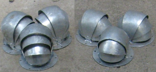
- Untitled.jpg (41.96 KiB) Viewed 6047 times
Re: Using OpenSCAD to produce drawings for 3D Printing
Posted: Wed Jan 05, 2022 6:48 pm
by metalmuncher
-steves- wrote: ↑Wed Jan 05, 2022 1:28 pm
Simon
How would you go about something like this? I can't even think of where to start, even in Tinkercad
I have had success with your domes and flares. I can now print any dome I like with minimal changes, I can't thank you enough for that
Untitled.jpg
I've had a bit of a go a that one. Just three "orange segment" shapes stuck together.
Not quite perfectly proportioned, maybe a bit of unequal scaling of the shells would make it better. I also didn't bother making the shells thin, depending on print scale such thin structures might not be easily printable, but the thin wall could be added relatively easily.
Code: Select all
$fn=64;

module ShellShape(width, straightlen, angle){
    rotate([90,90+angle/2,0])
        rotate_extrude(angle=angle)
            translate([-straightlen,-0,0])
                union(){
                    translate([0,-width/2,0])
                        square([straightlen,width]);
                    difference(){
                        circle(d=width);
                        translate([0,-width/2,0])
                            square([width/2,width]);
                    }
                }
};

union(){
    cylinder(d=11, h=0.5);
    ShellShape(8  ,3  ,60);
    ShellShape(7.8,2.5,120);
    ShellShape(7.4,2  ,160);
}
Re: Using OpenSCAD to produce drawings for 3D Printing
Posted: Wed Jan 05, 2022 9:36 pm
by SimonWood
-steves- wrote: ↑Wed Jan 05, 2022 1:28 pm
I have had success with your domes and flares. I can now print any dome I like with minimal changes, I can't thank you enough for that
Excellent! I'm still finding OpenSCAD fascinating, and enjoying the new uses it can be put to...
metalmuncher wrote: ↑Wed Jan 05, 2022 6:48 pm
-steves- wrote: ↑Wed Jan 05, 2022 1:28 pm
How would you go about something like this? I can't even think of where to start, even in Tinkercad
I've had a bit of a go a that one. Just three "orange segment" shapes stuck together.
Not quite perfectly proportioned, maybe a bit of unequal scaling of the shells would make it better. I also didn't bother making the shells thin, depending on print scale such thin structures might not be easily printable, but the thin wall could be added relatively easily.
Oh wow, this is great. I just stared at Steve's pics and scratched my head.
One thing I noticed is that the pivot point in the shells is not at the absolute tip of the 'segments'. So I had a fiddle adding in bluntness factor. I don't think it's helped much, it's made it more complicated and made the model worse at the same time! I had to add in a factor to make sure it disproportionately affected the 'top' shell since 'blunting' the shells with very large angles doesn't make much sense. Having looked up Ash's Patent Carriage Ventilators (I wasn't familiar with them) it looks to me like it's necessary to model the inner shells in two parts, bringing them closer together along the x-axis to give that almost parabolic cross-section in the x-z plane. But I'm too tired to do any more fiddling tonight!

Code: Select all
topShellAngle = 50; // [20:5:80]
secondShellAngle = 110;  // [80:5:140]
thirdShellangle = 160;   // [140:5:180]
bluntness = 0; // [0:0.5:5]
// Decrements in the radius of each shell
redrad = 0.2; // [0.1:0.1:0.5]
angles = [topShellAngle,secondShellAngle,thirdShellangle,180];
module ShellShape(width, straightlen, angle, bluntness){
    pf=bluntness*pow((1-angle/180),2);
    difference() {
        translate([0,0,-pf])
            rotate([90,90+angle/2,0])
                rotate_extrude(angle=angle)
                    translate([-straightlen-pf,-0,0])
                        union(){
                            translate([0,-width/2,0])
                                square([straightlen+pf,width]);
                            difference(){
                                circle(d=width);
                                translate([0,-width/2,0])
                                    square([width/2,width]);
                            }
                        }
            translate([-straightlen-pf-width/2-1,-width/2-1,-pf])
                cube([2*(straightlen+pf)+width+2,width+2,pf]);
    }
};
union(){
    cylinder(d=11, h=0.5);
    for (i=[0:3]) {
        ShellShape(8-redrad*i,3-0.5*i,angles[i],bluntness);
    }
}

$fn=64;
Re: Using OpenSCAD to produce drawings for 3D Printing
Posted: Thu Jan 06, 2022 9:10 am
by -steves-
OMG!

How do you guys do this? I must admit I tried reading through the code to see how to make it bigger / smaller and I just don't have a clue, completely lost me on this one, but very well done
Re: Using OpenSCAD to produce drawings for 3D Printing
Posted: Thu Jan 06, 2022 9:15 am
by philipy
-steves- wrote: ↑Thu Jan 06, 2022 9:10 am
OMG!
How do you guys do this? I must admit I tried reading through the code to see how to make it bigger / smaller and I just don't have a clue, completely lost me on this one, but very well done
Glad it's not just me.


I
think I could see how to do this in Sketchup. I'd have a go but I'm a bit tied up with the contractors loco atm.