Styrene sheet moulding - Quintus build - FINISHED

Doesn't sound daft at all, it's the obvious comment. The only problem is that there was no sign of curl before I heated it and I have no idea which way up it was or which way round I cut it from the big sheet, so if I try again there is a 50-50 chance of repeating it!MDLR:114562 wrote:This might sound daft, but would it have worked better if the sheet was the other way up, so you could mould WITH the tendency to curve, instead of against it?
Philip

HIPS sheet always turns into a potato chip when heated past the softening point if it isn't restrained. As far as I know, it is made by extrusion and then finished by rolling to get a shiny surface, or a textured one like Evergreen sheet. You can feel the directional difference in the properties if you bend a piece of sheet in your hands. It bends easier in the extrusion direction than at right angles to it. ie. it is stiffer along the extrusion than across it.philipy:114560 wrote:Well, the first attempt at hot moulding was spectacularly unsuccessful!
The styrene sheet I used must have some sort of built-in curl which was flattened when the sheet was rolled, because as soon as it started to soften it also started to curl up and inwards! It's a pity really because it has nicely draped over the curves.
You probably got it a bit too hot as well, but the frame I described is important to restrain the sheet from curling up when hot. HIPS sheet is clamped in a frame for the same reason when vac forming.
The transition temperature for HIPS is quoted as being around 105C. Note it is plastic sheet temp. not air temp. The oven will need to be a bit hotter than that, as air is a lousy heat transfer medium, but as soon as the sheet starts to sag, it is ready to form.
A small sample will distort in the same way as the whole sheet, so you can test a coupon a couple of inches across to work out what the whole sheet will do. If you mark it, you can then orient later pieces so the stresses in the sheet work in your favour.
My first attempt wasn't much better. As with most things, practice makes perfect...........
Only you can decide that. The question to ask yourself is are you building a scale model of Quintus at some particular time in it's history, or are you making a MW class E special for your railway. If the latter, then go for the appearance that you prefer.philipy:114560 wrote:Since the sheeting and flap are obviously subsequent mods, I'm in two minds about doing away with them on both sides.
Regards,
Graeme
Quick update...
I decided that it since I had taken Peter's suggestion and had already made a laminated tank shell, it would probably be quicker, and more economic in material terms, to carry on with that, rather than have several more attempts at moulding to get one that was acceptable.
It took me almost exactly 2 hours to shape the tank, starting from the simple box with internally blocked out corners, and I reckon it could easily have taken the same time to get the moulding method right.
So, for a one-off, I don't think there is much to be gained either way. Of course once the moulding method was nailed down, it would then be pretty fast to make several identical units.
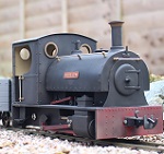
However, overall the loco is progressing fairly well, I think, as the photo shows ( Ignore the cotton bud its just there to prop up the back end of the boiler!). At the moment the footplate, cab, tank and boiler, and smokebox are still 4 separate items.

Edited to add: Oops, just noticed that the cab is back to front!
I decided that it since I had taken Peter's suggestion and had already made a laminated tank shell, it would probably be quicker, and more economic in material terms, to carry on with that, rather than have several more attempts at moulding to get one that was acceptable.
It took me almost exactly 2 hours to shape the tank, starting from the simple box with internally blocked out corners, and I reckon it could easily have taken the same time to get the moulding method right.
So, for a one-off, I don't think there is much to be gained either way. Of course once the moulding method was nailed down, it would then be pretty fast to make several identical units.
However, overall the loco is progressing fairly well, I think, as the photo shows ( Ignore the cotton bud its just there to prop up the back end of the boiler!). At the moment the footplate, cab, tank and boiler, and smokebox are still 4 separate items.
Edited to add: Oops, just noticed that the cab is back to front!
Last edited by philipy on Fri Dec 04, 2015 6:01 pm, edited 1 time in total.
Philip
-
Peter Butler

- Driver

- Posts: 5291
- Joined: Sun Sep 09, 2012 10:33 pm
- Location: West Wales
This has been an interesting journey and the comparisons make it useful for others to make their own decision. Your laminated tank certainly looks good and appears to be straight (no distortions) and evenly shaped both sides. Well done and thanks for the progress report.
The best things in life are free.... so why am I doing this?
Following on from the earlier posts about the best way to form a MW saddle tank, I thought I'd do a bit of an update on the loco build. For a couple of reasons I've decided that I'm not building "Quintus", but I am building another member of the class, as modified by the Elderbury & District Light Railway to suit their particular needs. However, in keeping with the spirit of Quintus, she will eventually be called Octavius, being No.8 in the E&D numbering series.
The build is progressing slowly and although the body doesn't appear to have changed much externally in the past 2 months, along the way I have:
1) Learned to program the Deltang Rx 65b to give me the guards whistle and loco whistle from a MyLocoSound card ( Many thanks to Rik for his blogs and PM's).
2) I use the Tx in 'centre-off ' mode so I have modified the Deltang Tx by replacing the direction change switch by two push buttons for the whistles.

3) I have modified the MLS soundcard by removing their standard huge green screw-terminal sets, and simply soldering the connections to the pcb, to give a significantly lower profile to the unit.
4) I have installed a false ceiling under the cab roof and built in a hidden compartment which holds both the Deltang Rx and the modified soundcard.


5) The GRS chassis was about 14mm shorter than the Quintus drawings require, so I made a new, extended, rear chassis spacer and this in turn also allows me to get a 50mm diam speaker between the frames under the cab floor.

6) Modified the tank/boiler assembly so that the smokebox, boiler bottom, cab and footplate are now one rigid unit and the tank lifts off to give access to the battery. I decided this was necessary so the battery can be removed for charging. It is a big Li-Poly and all the warnings say to remove for charging because of the risk of fire, plus if it does get warm it may not do the styrene body much good!
7) I've made a start on the firebox. This will be screwed in eventually and will hold the auto-resettable fuse and various plug/sockets to allow the electrical bits and pieces to be removed individually if necessary.

More updates to come, as and when.
The build is progressing slowly and although the body doesn't appear to have changed much externally in the past 2 months, along the way I have:
1) Learned to program the Deltang Rx 65b to give me the guards whistle and loco whistle from a MyLocoSound card ( Many thanks to Rik for his blogs and PM's).
2) I use the Tx in 'centre-off ' mode so I have modified the Deltang Tx by replacing the direction change switch by two push buttons for the whistles.
3) I have modified the MLS soundcard by removing their standard huge green screw-terminal sets, and simply soldering the connections to the pcb, to give a significantly lower profile to the unit.
4) I have installed a false ceiling under the cab roof and built in a hidden compartment which holds both the Deltang Rx and the modified soundcard.
5) The GRS chassis was about 14mm shorter than the Quintus drawings require, so I made a new, extended, rear chassis spacer and this in turn also allows me to get a 50mm diam speaker between the frames under the cab floor.
6) Modified the tank/boiler assembly so that the smokebox, boiler bottom, cab and footplate are now one rigid unit and the tank lifts off to give access to the battery. I decided this was necessary so the battery can be removed for charging. It is a big Li-Poly and all the warnings say to remove for charging because of the risk of fire, plus if it does get warm it may not do the styrene body much good!
7) I've made a start on the firebox. This will be screwed in eventually and will hold the auto-resettable fuse and various plug/sockets to allow the electrical bits and pieces to be removed individually if necessary.
More updates to come, as and when.
Philip
-
-steves-
- Administrator

- Posts: 2445
- Joined: Thu Jul 28, 2011 1:50 pm
- Location: Cambridge & Peterborough
Not sure how much you have used li-po's, but I will say, NEVER fully charge it and then don't use it. Even if its just for a day, make sure its between 40% and 65% charged, anything else can cause major swelling of the pack or depending on temp of then charged and when stored, it can actually over charge whilst standing and just go up in flames, these things create their own oxygen and don't need any help is making a major mess fast. Seen a few packs go up at the RC flying field over the years and I have a box fell of swollen ones which I need to throw away asap. A good friend of mine no longer has a garage because of them and lost around 20K worth of large radio controlled planes in the process. I love em for high current drain applications (like RC planes and cars), but correct storage charge is essential, also never charge them anywhere you don't mind being burnt, just in case, it might not happen, never done it to me, but it DOES happen. Personally sticking to LI-FE and Li-Lo's for RC trains now as much less risk with those and you don't need the current draw that a Li-Po provides ;)
Other than that word of warning for everyone, the loco looks great so far, doing a grand job :D
P.S. Always balance charge these packs and regularly check the individual cell voltages before and after a charge, just to make sure one isn't going off, if one does start misbehaving, drain the pack, stick it in salt water over night, cut the wires off it and bin it.
The buck stops here .......
Ditton Meadow Light Railway (DMLR)
Member of Peterborough and District Association
http://peterborough.16mm.org.uk/
Ditton Meadow Light Railway (DMLR)
Member of Peterborough and District Association
http://peterborough.16mm.org.uk/
Steve,
Thanks for the advice, I don't have a lot of experience with these things. I did read as much as poss before going ahead, but personal experience is always valuable.
Yep, I have a balance charger and have spoken to a tech adviser at Hobbyking ( who suppled both battery and charger) so am aware of the storage and self-combustion issues.
Thanks again.
Philip
-
-steves-
- Administrator
- Posts: 2445
- Joined: Thu Jul 28, 2011 1:50 pm
- Location: Cambridge & Peterborough
Excellent, then I am sure it will be great. The balance charger might show you the voltage status of each cell during charge, on most balance chargers with a display you simply "press one of the buttons" and it will change between overall charge status of the pack to individual cell voltage, very handy.philipy:116072 wrote:Steve,
Thanks for the advice, I don't have a lot of experience with these things. I did read as much as poss before going ahead, but personal experience is always valuable.
Yep, I have a balance charger and have spoken to a tech adviser at Hobbyking ( who suppled both battery and charger) so am aware of the storage and self-combustion issues.
Thanks again.
Personally over the years I have never had one go up, so they aren't all that bad and I have abused them, lots. It doesn't take abuse for them to pop, just bad luck I think, but if one is hissing, do not pick it up or try to move it, it will seriously burn.
I am pleased HobbyKing were helpful, they have always had good customer service for me too.
Sorry, I digress, cracking on with the build sir.
The buck stops here .......
Ditton Meadow Light Railway (DMLR)
Member of Peterborough and District Association
http://peterborough.16mm.org.uk/
Ditton Meadow Light Railway (DMLR)
Member of Peterborough and District Association
http://peterborough.16mm.org.uk/
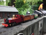
It's been a long time coming but finally the body has been outshopped in works grey!
I still need to do some work to the GRS chassis - trimming down those massive cylinders and valve chests to something closer to the prototype and adding a second dummy slidebar, for certain.
Plus, ideally removing the balance weights from the cranks, has anyone any experience of doing that?

I still need to do some work to the GRS chassis - trimming down those massive cylinders and valve chests to something closer to the prototype and adding a second dummy slidebar, for certain.
Plus, ideally removing the balance weights from the cranks, has anyone any experience of doing that?
Philip

-
Peter Butler
- Driver
- Posts: 5291
- Joined: Sun Sep 09, 2012 10:33 pm
- Location: West Wales
I totally agree, that is an excellent model, well thought out and constructed. I do like to see them in works grey before the final coat when all of the component parts are given the same degree of importance, which is probably why the cylinders etc stand out more at this stage.
The best things in life are free.... so why am I doing this?
Thanks for the comments, guys.
Graham, I may well paint them as you suggest, to start with at least, but I'm inclined to take a Dremel slitting disc to them, longer term.
Grant, thanks.
Peter, you may be right that the colour difference make the cylinders stand out, but they are definitely oversized for this loco and the MW doesn't have the big square valve chests either. I'm thinking they need taking down to the same diameter as the end plate. Even then they will be a bit big but I can live with them at that size.
Philip
Rik,ge_rik:117601 wrote:Wow!! She sure is looking good, Philip.
Can I just ask where you source your pipework fittings? Did you scratchbuild them, bash them or buy them? They're the finishing touch which certainly brings the model to life.
Rik
A bit of all of those options, the expression "bodgeling" springs to mind!
Most of the basic pipework is brass or nickel silver wire/rod. The flat sections, i.e, reversing rod etc, are nickel silver. Most of it is stock, some dating back 20 odd years to my active 4mil days! A few bits were purchased from Eileens Emporium.
After that its a matter of adding bits and pieces of brass and styrene tube etc, so that things look about right, working from the drawings in SMT and the photo's.
As a f'rinstance, the lubricators in front of the smokebox:
These started with a small piece of white ABS tube for the body, then drill a small transverse hole right through and insert a length of ABS rod right through and glue it.
Cut a small ring of ABS tube and fit it onto a small flat head brass pin ( inherited from my dad in a box of junk!), give it a good soak of "Plasticweld" which rounds the edges.
Then cut the brass pin down to a suitable length and insert into the top end of the original tube.
Next get a piece of brass wire of a suitable diameter for the bottom feed tube and drill up from the bottom of the main body to cut through the cross piece.
Squirt a little drop of superglue into the body and insert the wire, once it has set, bend the wire to shape.
Then trim the cross piece to length both sides and glue on a very small piece of plasticard rod, to act as the handle of the valve.
Took about an hour to make two of them, including some bits that dropped on the floor and weren't worth searching for!
The handrail knobs are D-shaped brass wire ( e-bay) squeezed round the the handrail rod.
Rod, wire, tube and small washers can be transformed into all sorts of things with a bit of imagination!
Philip
I suspected as much - they are a credit to the work which went into them. I do enjoy hearing about the ingenuity of fellow modellers - especially when it comes to fine detailing.philipy:117611 wrote: Rik,
A bit of all of those options, the expression "bodgeling" springs to mind!
Most of the basic pipework is brass or nickel silver wire/rod. The flat sections, i.e, reversing rod etc, are nickel silver. Most of it is stock, some dating back 20 odd years to my active 4mil days! A few bits were purchased from Eileens Emporium.
After that its a matter of adding bits and pieces of brass and styrene tube etc, so that things look about right, working from the drawings in SMT and the photo's.
As a f'rinstance, the lubricators in front of the smokebox:
These started with a small piece of white ABS tube for the body, then drill a small transverse hole right through and insert a length of ABS rod right through and glue it.
Cut a small ring of ABS tube and fit it onto a small flat head brass pin ( inherited from my dad in a box of junk!), give it a good soak of "Plasticweld" which rounds the edges.
Then cut the brass pin down to a suitable length and insert into the top end of the original tube.
Next get a piece of brass wire of a suitable diameter for the bottom feed tube and drill up from the bottom of the main body to cut through the cross piece.
Squirt a little drop of superglue into the body and insert the wire, once it has set, bend the wire to shape.
Then trim the cross piece to length both sides and glue on a very small piece of plasticard rod, to act as the handle of the valve.
Took about an hour to make two of them, including some bits that dropped on the floor and weren't worth searching for!
The handrail knobs are D-shaped brass wire ( e-bay) squeezed round the the handrail rod.
Rod, wire, tube and small washers can be transformed into all sorts of things with a bit of imagination!
I'm afraid my fingers become thumbs when I try doing the fiddly bits - but I'm willing to have another go after reading your descriptions.
Rik
Who is online
Users browsing this forum: No registered users and 1 guest