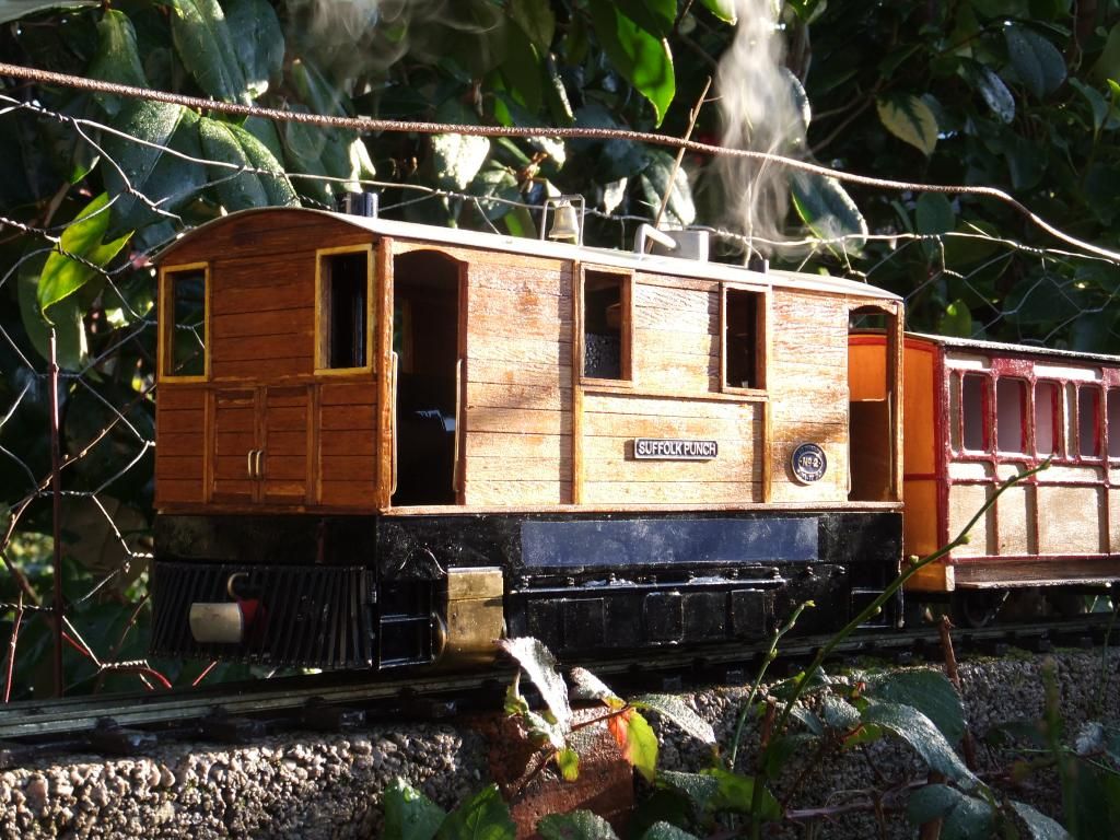

I have been meaning to do this for a while, but here it is. I wanted to post about my first 'built' or 'bashed' locomotive Suffolk Punch. I originally posted about this model on the Mamod forum here:
http://modelsteam.myfreeforum.org/ftopi ... -asc-0.php
I have dissected the thread to include the relevant build information, although this will be a lengthy post or two. For that I apologise, but I want to record my goings on here too.
Below are the posts from the other forum:
Tue May 21, 2013 10:15 pm
I know these trams aren't exactly everyone's cup of tea, but I really like them.
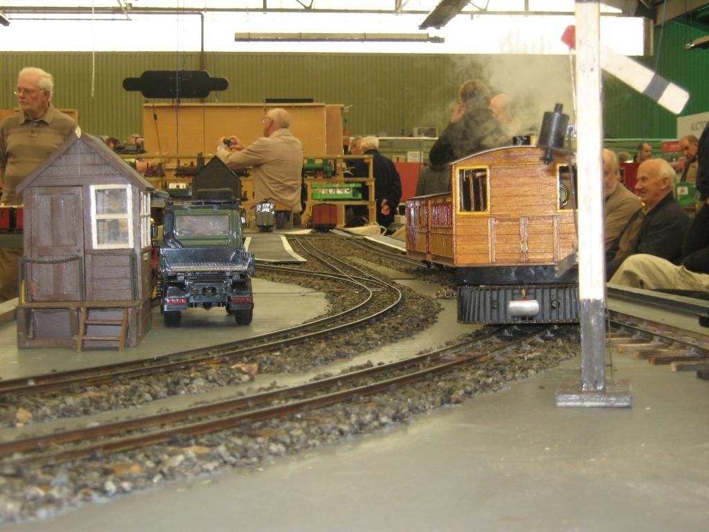
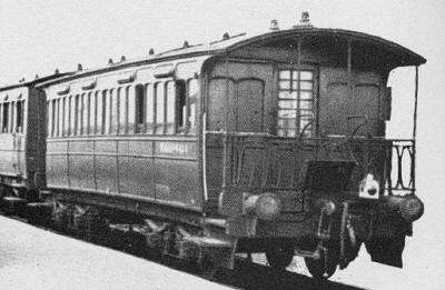
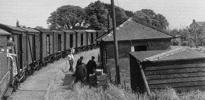
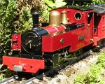
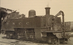
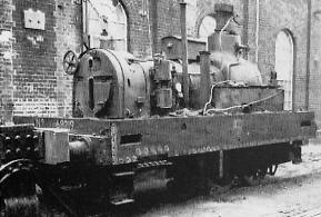
Below is a J70 Tram that ran on the Wisbech & Upwell tramway. This one in particular (68222) is what I want to build mine like as a tribute to its existence, last one left standing.
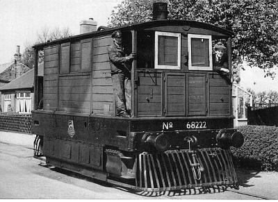
I suppose my love of these engines were brought on by my childhood years, brought up watching 'Thomas the tank engine'. Toby was my favourite engine, just because he was different. Anyway fast forward 25-28 years and here I am putting together my own 'Toby'. A little research taught me that none of these engines exist any more and that when they did they had a somewhat 'fruitful' life on the Wisbech and Upwell route.
Having read the LNER website, see here http://www.lner.info/co/GER/wisbech/, I found myself really quite interested in the history of these unusual yet different engines.
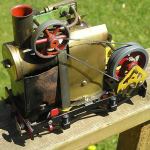
So back to now. I decided that I wanted a Tram. How was I going to build one and what parts was I going to throw at it? I initially thought about using a Mamod setup, 0-4-0, oscillating cylinders and build to a strict budget. I have never built a loco before, so I decided to keep things as painless as possible.
My mock up rig with Mamod side frames, spare roundhouse boiler and a couple of sheets of card. This was very unstable.
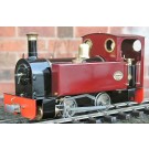
But then having done a little testing and research I found that this was definitely not the way to go. Mamod locos have their faults, believe me I own probably about 10 or so and I also had to overcome the standard gauge problem. I am lucky enough to own a roundhouse 'Billy' loco, bought circa 1996. This is radio controlled and gas fired and is multiple levels of refinement better than a Mamod. So a little searching brought me back onto the roundhouse website and before I knew it I had ordered a 'Lady Anne' chassis kit as a base to get on with.
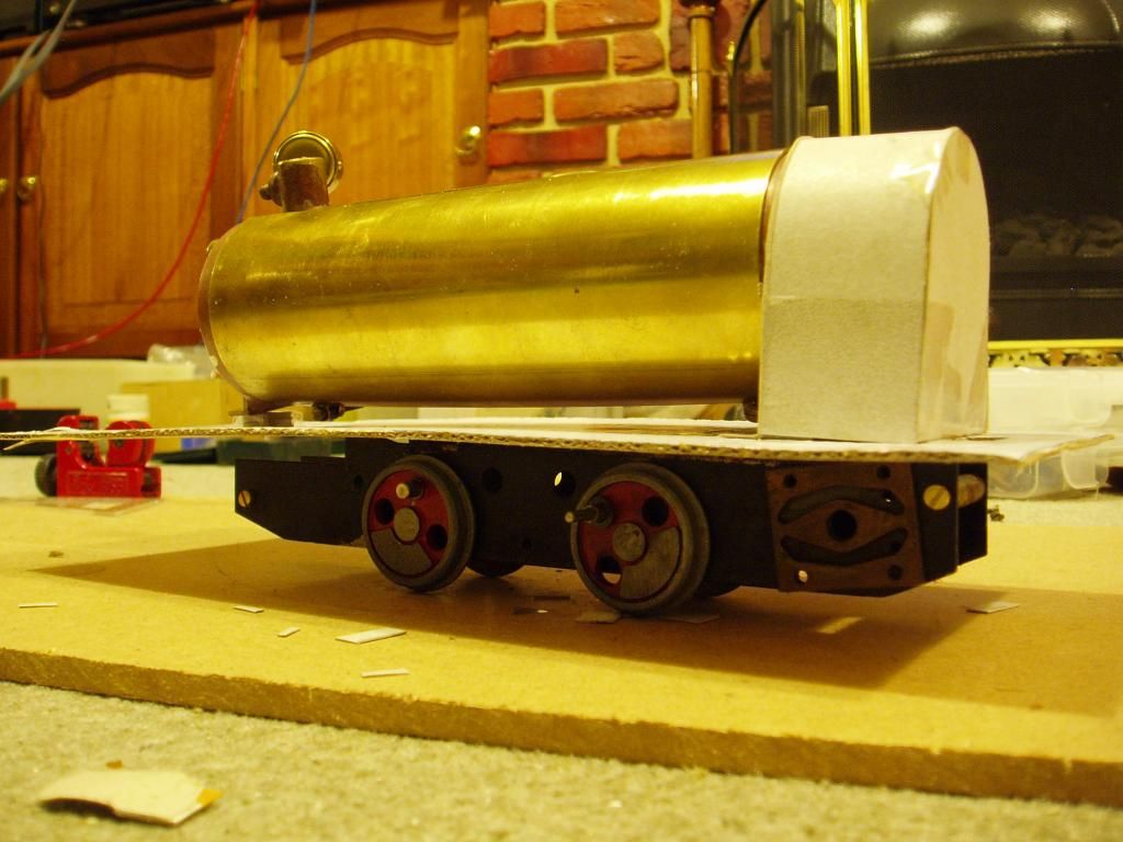
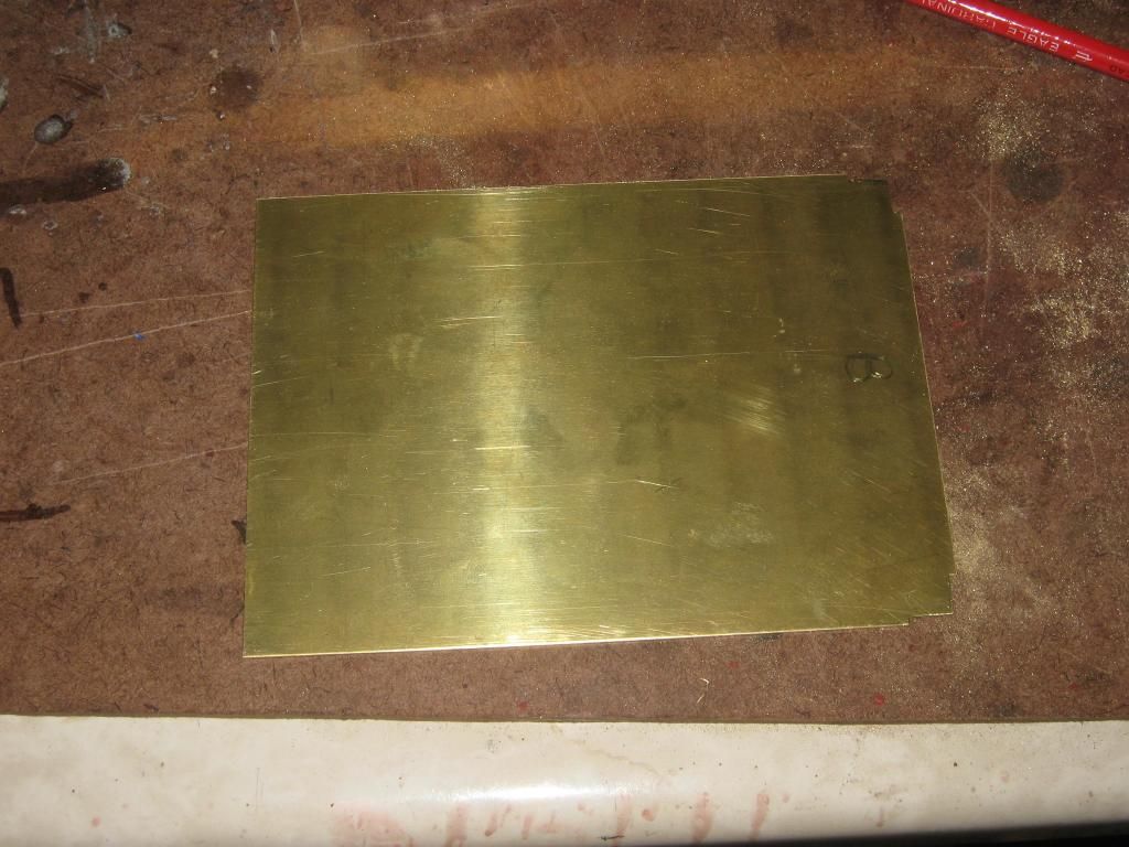
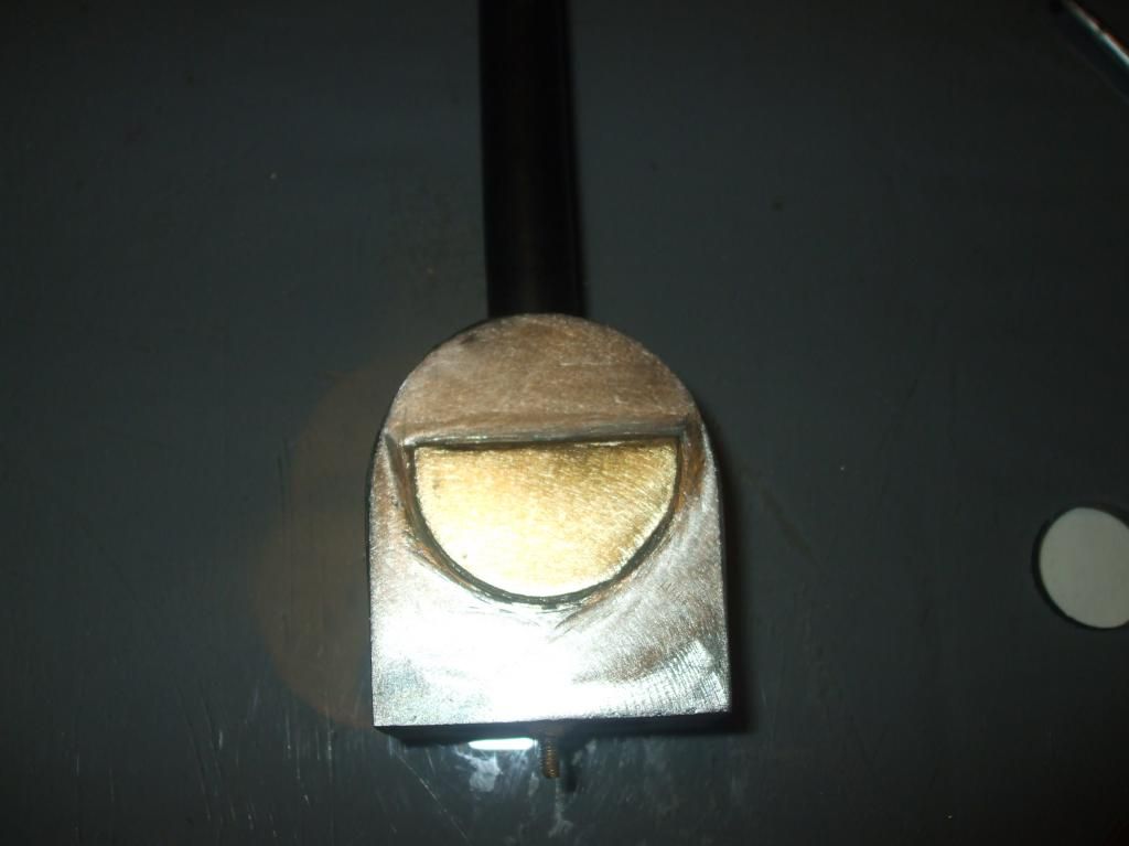
Whilst the chassis kit was in the post I started making the smoke box. I knew what height the boiler was going to sit and I knew how I was going to mount on the chassis kit (all in my head). So I stared with this. Cut from mild steel sheet (18 gauge) and silver soldered together.
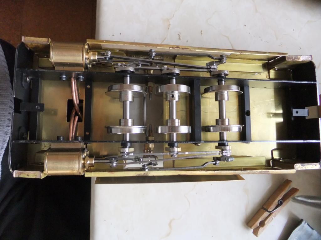
Then the chassis kit arrived and I started with this,
And ended eventually with this
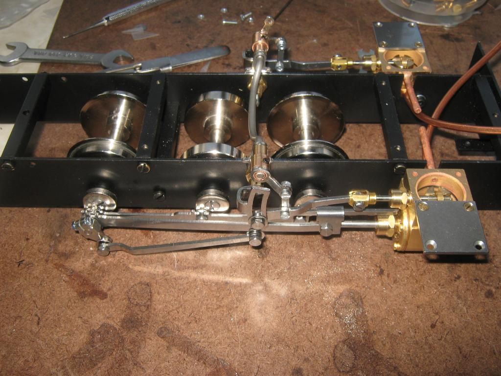
I am a little unsure if I have the valve gear set correctly, so I will have a bit more of a play once I have built the body. I will post some of that tomorrow.
Wed May 22, 2013 5:52 pm
Thanks for the kind replies and loose nut 45, thanks for that link! It just goes to show that the trams are gone but not forgotten.
Well, a small update. I had to make a decision on what sort of scale to built this tram. I decided to not model the whole thing on a perfect scale but to match the common size of 32mm rolling stock so that coaches and vans would not look undersized behind it, like some narrow gauge locos dwarf their wagons. Just so it looks right to me.

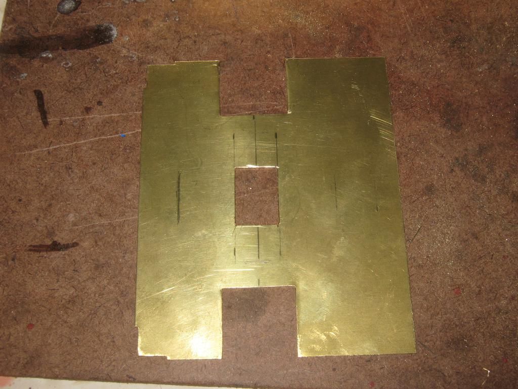
I stared with the floor pan side of things. Make a tub and fix the top into it. I apologise for the poor soldering, I have not done alot of it. :?
The sides
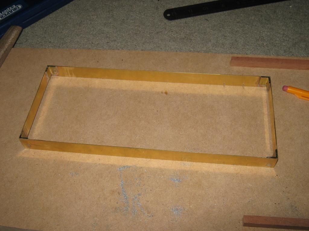
Sitting on the frame
A small cut out required for the valve chest.
I may pop rivet the corners together too or add some rivet detail later on, what do you guys think?
I'll get on to fitting the actual floor of the tub a little later when I have uploaded the photos.
Wed May 22, 2013 9:47 pm
Anyway, I have been up to a little more this evening. See below:
Rear floor pan
Front floor pan
Almost complete floor tub
And add some angle
I think that will be all for this evening. :)
Thanks for the encouraging comments and advice guys. I will have a think on the rivet detail in more time.
Fri May 24, 2013 7:28 pm
A small update...
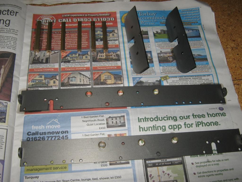
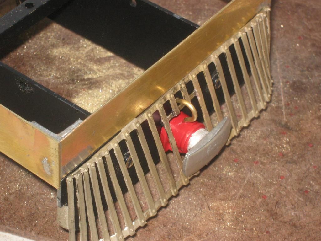
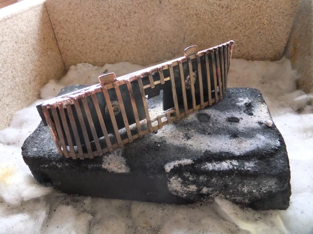
I have dug out a pair of cow catchers that I bought for this project some time ago and evidently they need modifying to accept the centre buffer.
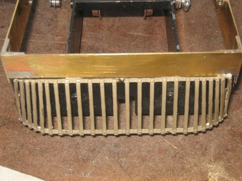
They did however require alot of bending and messing about to get them to fit this well on the buffer beam.
A little cutting and soldering I ended up with what I have below. I used the material that I cut out to fill in the horizontal stiffeners.
I also made some steps to fit below the doorways for my new crew to climb and enter this engine. Made out of some hand bent brass sheet and a little solder. I really like soldering, kinda therapeutic when all goes well. Again I apologise for the mess. :? I know they aren't perfectly straight, but I think it adds to the character of being knocked about and used.
I'll start on the side plates/wheel covers a little later. :)
Tue May 28, 2013 11:48 am
Time for a quick update. Over the weekend I did have a bit of a break from the tram and brightened up a Mamod SL4 'PRINCESS OF WALES' loco that I bought on the 'bay about a year ago. She was in a sorry state and I think I have done an ok job in bringing her back to a happier condition. I may post my work a little later.
Anyway, back to the task in hand. :)
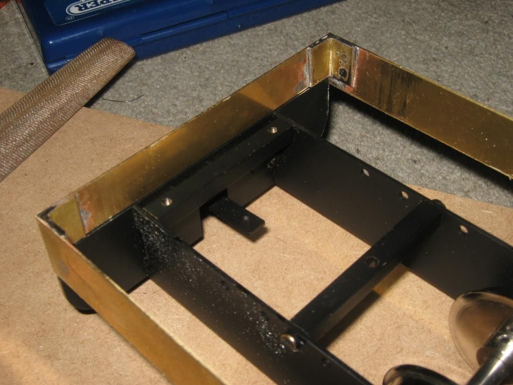
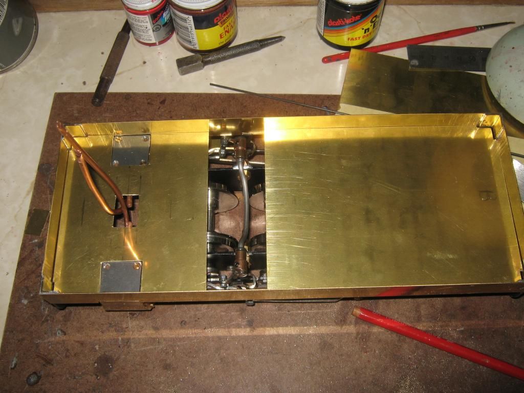
I decided to crack on with the side plates and access panels. As previously mentioned by another member to have them opening so the mechanics are visible. I pondered for quite some time for a practical and relatively simple design to build with the skills I have.
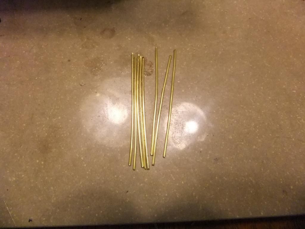
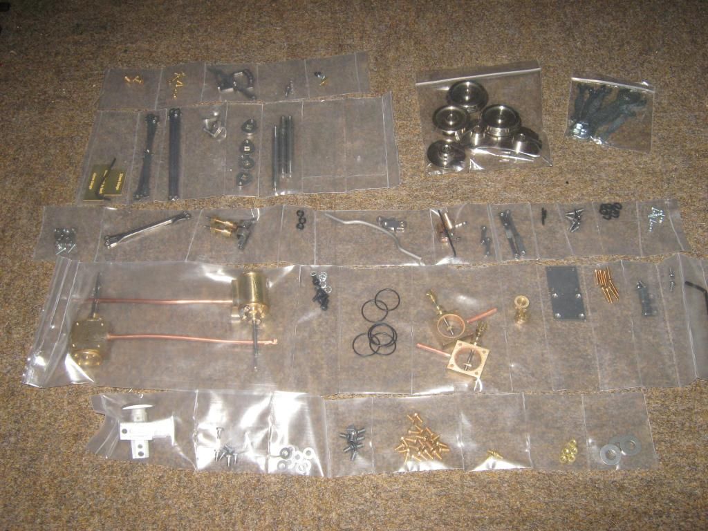
The order of parts
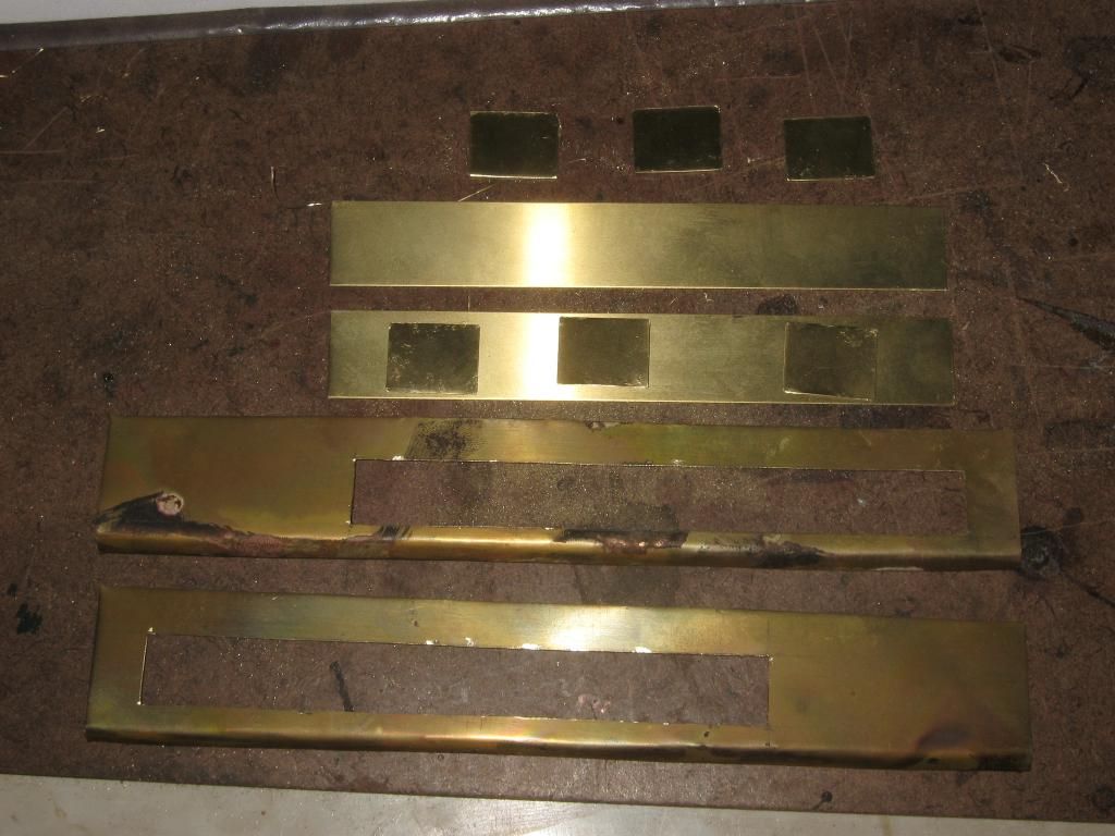
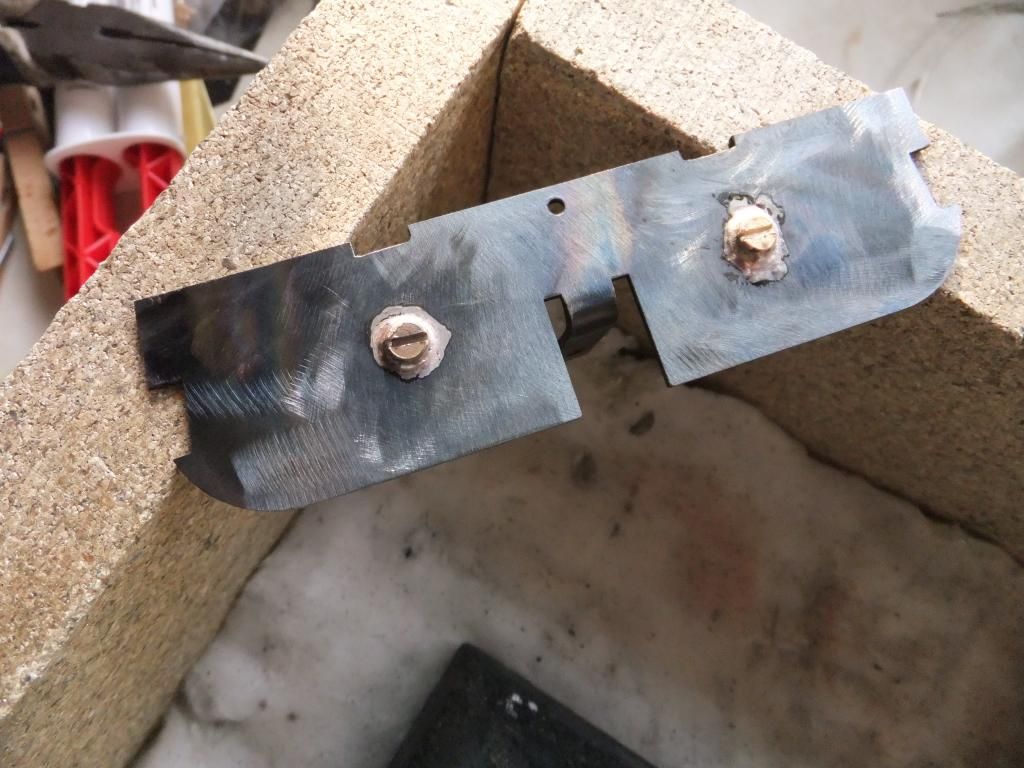
The bottom lip of the side panels I bent inwards and folded the edge and soldered for some added strength.
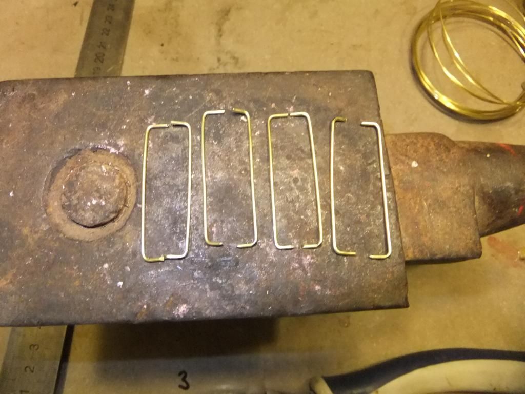
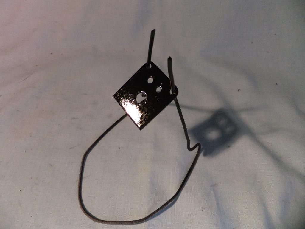
I then spent a little time at my local hobby shop looking at various model aircraft hinges and other parts to try and make these flaps functional. I could not find anything that would do the job well enough so I used some brass tube and piano wire and made these.
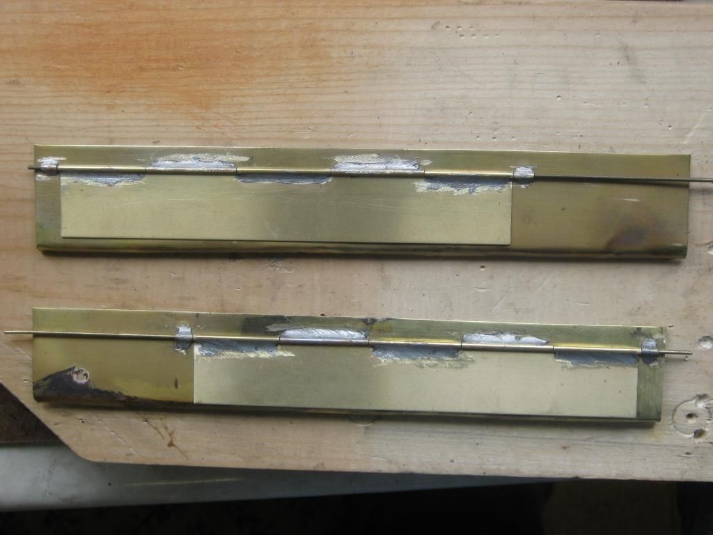
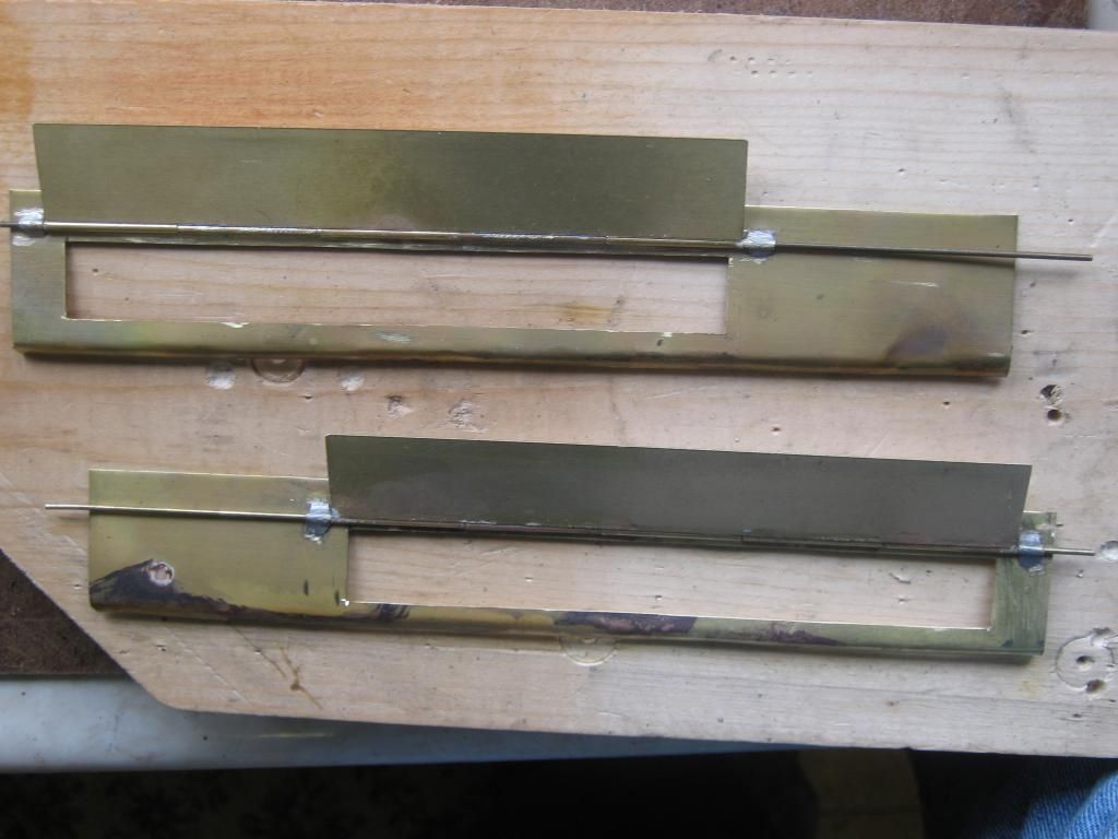
I don't think the home made hinges are too obtrusive, I figured that the smaller access panels would have to be cosmetic and either glued or soldered in place.
Wed May 29, 2013 8:32 pm
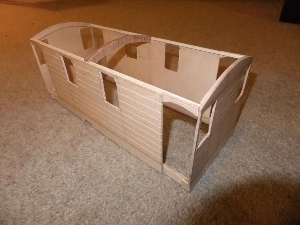
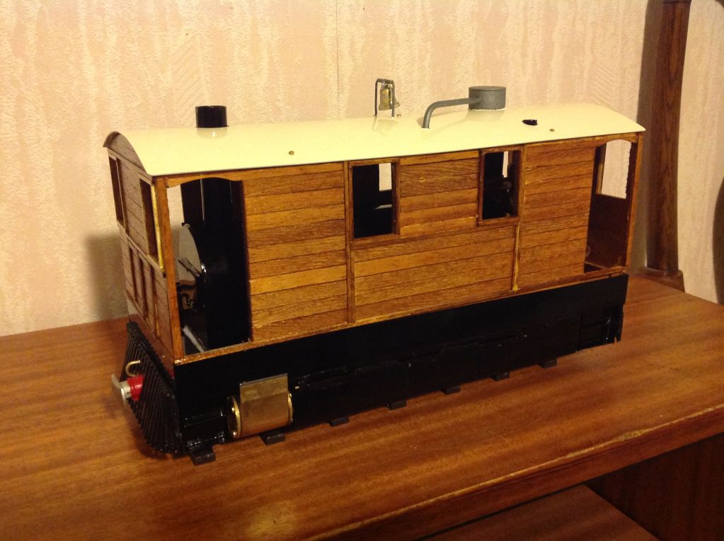
Today I did some woodwork and some more metalwork. I have finally come up with the size that I think looks right on my loco. It does match in nicely with existing coaches and rolling stock.
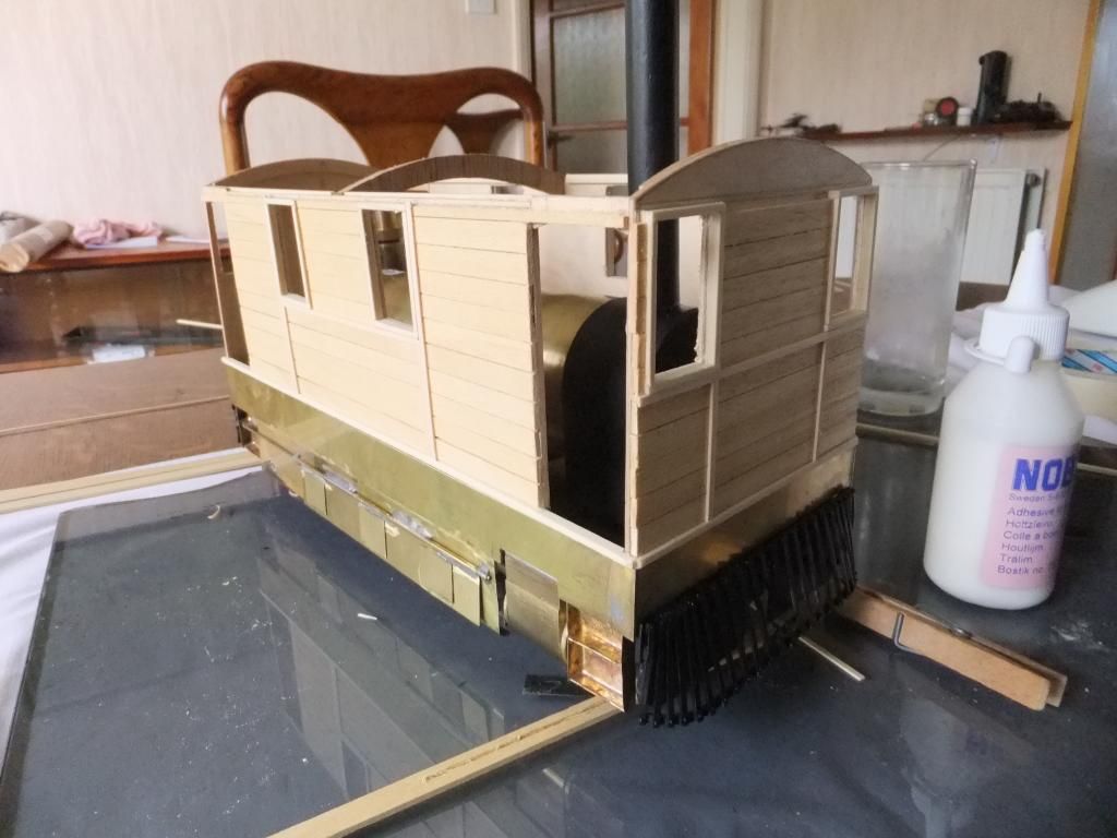
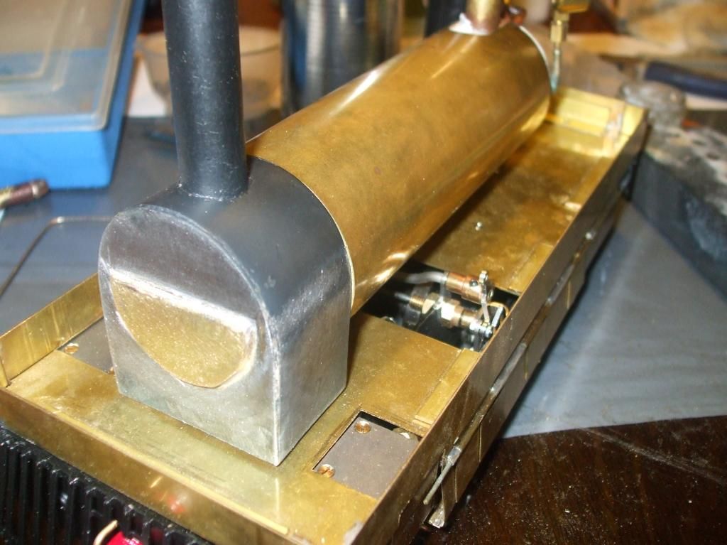
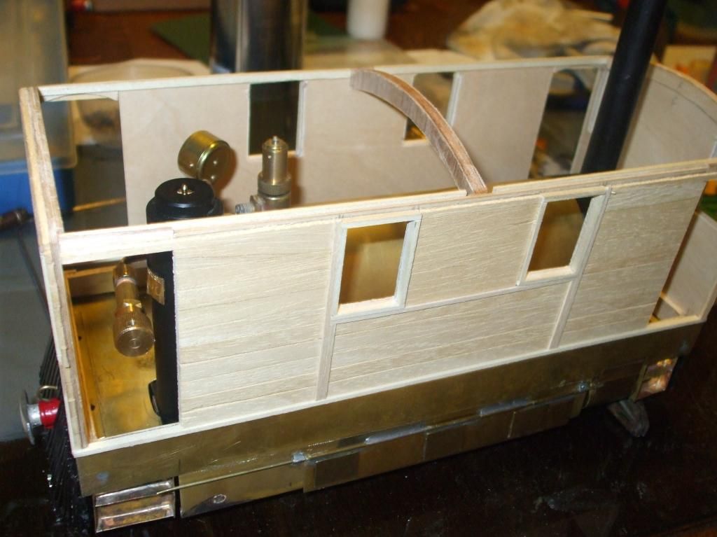
Here is the upper body in sections, mid trial assembly.
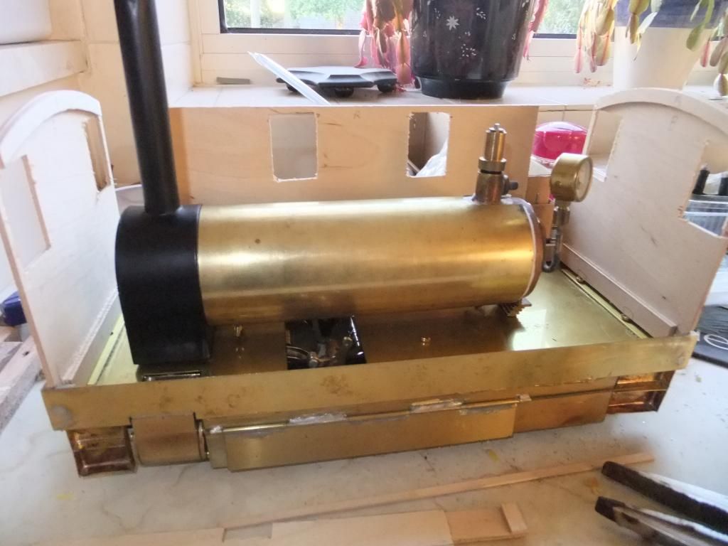
It gives me, for the first time, the idea of how much room I have. Not much room at the front end for dummy controls. :?
Keith, I did as we both said. Had the false inspection doors on the main inspection door.
I also soldered on and finished these off.
and fitted the cab steps and side plates
So this evening, I have these. :)
I also went along to my local model shop, picked up some strips of wood for the detail and for cladding of the ply. I just scoured and drew on the final details to give me an idea of sizes/scales.
I hope you guys like. I am quite pleased so far. My first built loco is being born. :P
Fri May 31, 2013 8:06 pm
Thanks for your opinions guys. I do feel something should be done and Keith, yes it does bug me immensely and I had intended to fit the lower rail between cow catcher and side plate. Before Pauly posted his very valid point I was going to whip out the blow torch and pull them back off again.
But...... If it really means it, I would rather sacrifice the look in favour of trouble free running. That would annoy me more I think.
I have looked at the construction and I can leave the buffer beams until the end. They merely unbolt from the chassis frames.
I really, really do want to change them but I know that if I experience fouling on the rail as a result of lowering the cow catchers I will hate myself even more.
I really wish I had paid more attention upon trial fitments and had come across this problem before. Oh well, lesson learned.
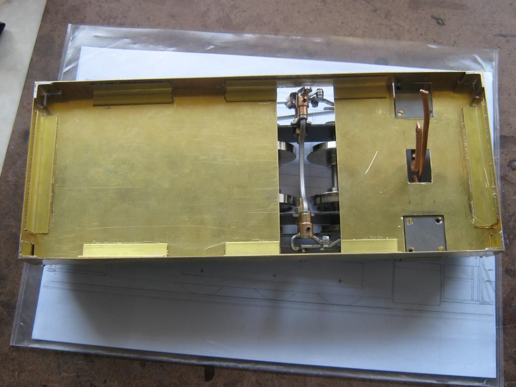
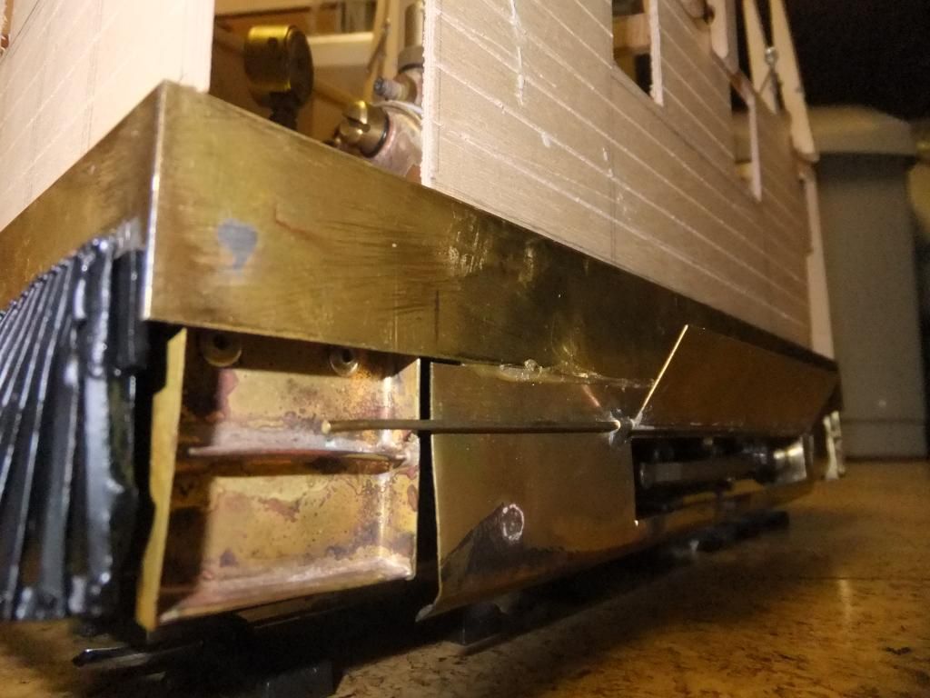
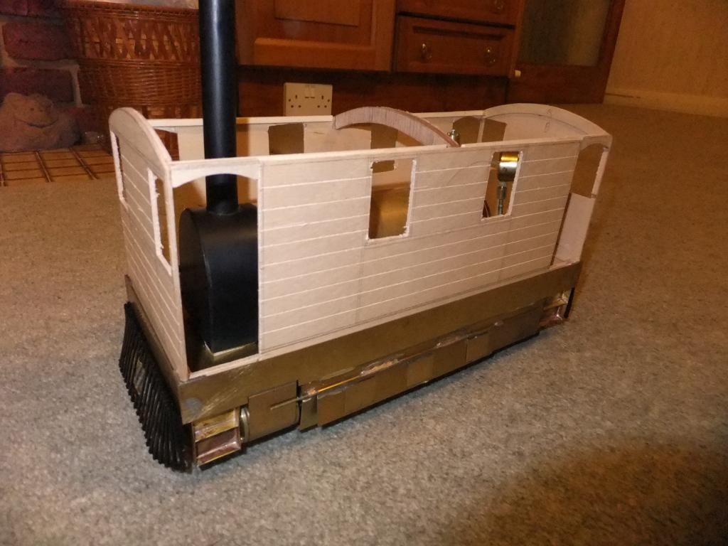
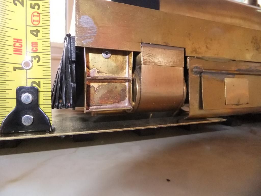
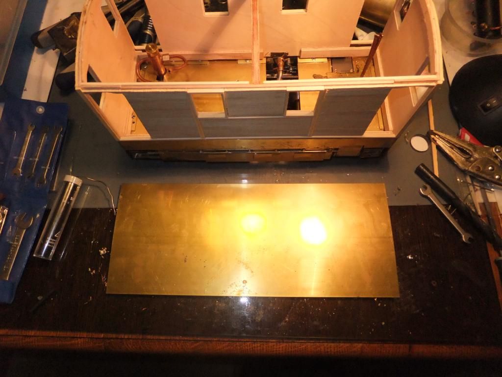
Having typed all that, I have just put the loco on the rails and rested a sheet of brass on the rails. As Keith put, I cannot do anything about the cylinders... that said I will have to work and compromise around them.
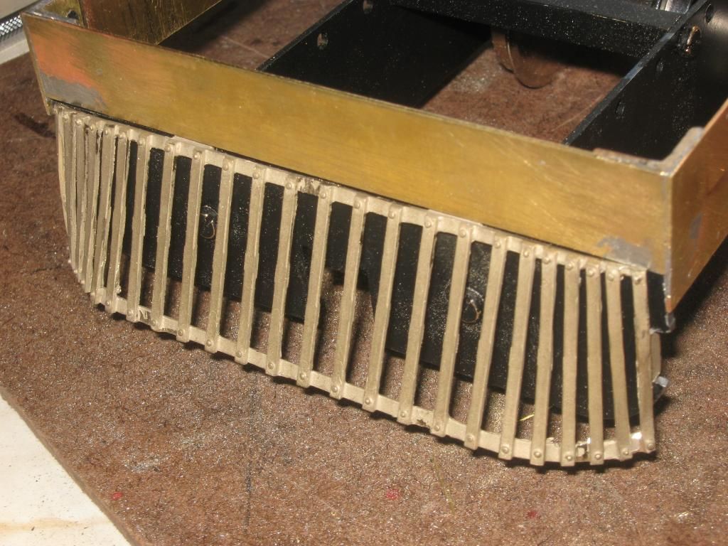
Looking at the photo below, the 'catcher is 8mm +/- above rail height, the side plates on the other hand just kiss the brass sheet. I think it is the side plates that are too low. If I raised them then the overall look would be better and I would have some clearance and a bit of tolerance with the rail. I would have to loose the joiner between the 'catcher and the side plate, not such a big deal? Any input guys?
Sat Jun 01, 2013 9:42 pm
Well I did it. Pulled off the side plates and trimmed and tightened up the bend on the bottom.
How is this for a line up?
They are probably a little lower than I would like but I had to compromise with the mechanics of the side rods. I want a lip along the bottom for rigidity but I cannot raise them too much otherwise I will fowl the motion.
This problem has been a mass of compromises. Everything just about clears everything else. But its done. :D
OCD pains fading, I can sleep soundly tonight!

Sun Jun 02, 2013 8:06 am
Thanks for the support guys. I had been cracking on with the wooden body, altering the side plates whilst glue was drying. I am a little further on than the pictures, but you get the general idea.
Perhaps I'll post the latest pictures a little later on today.
Now onto the next question, I read on the LNER site that the BR coloured J70 trams were black frames and black wooden body. I wanted to really number and colour this tram as if it were still in the GER days. So that means black frames and brown wooden body.
I have found some conflicting information as to 68222's original numbering. The BR database will have you believe that the GER numbered this loco as '128'. See here
But the LNER website says that the older Y6 trams were numbered from 125 to 131, see here
I see that some Y6 trams were withdrawn when the J70 trams were introduced, 128 included, so I wonder if the GER used the recently redundant numbers to number the newer J70's? Can anyone shed any light?
I know is a little sad, but I want to number this loco correctly. :roll:
Mon Jun 03, 2013 10:30 pm
Thanks for the explanation on kit bashing. I am glad I chose the RH Lady Anne to base on, it seems to be a good model to run anyway. I would like one some day. I just hope that my ugly tram can do the prestige chassis and boiler justice!
I only have a small update I'm afraid. I am getting sick of this cladding and detail work right now, I didn't like woodwork at school and I still don't. Give me some metal to work with any day.
I'm going to put the body to one side and work on the smoke box and possibly get started on the lines and servo locations for the r/c.
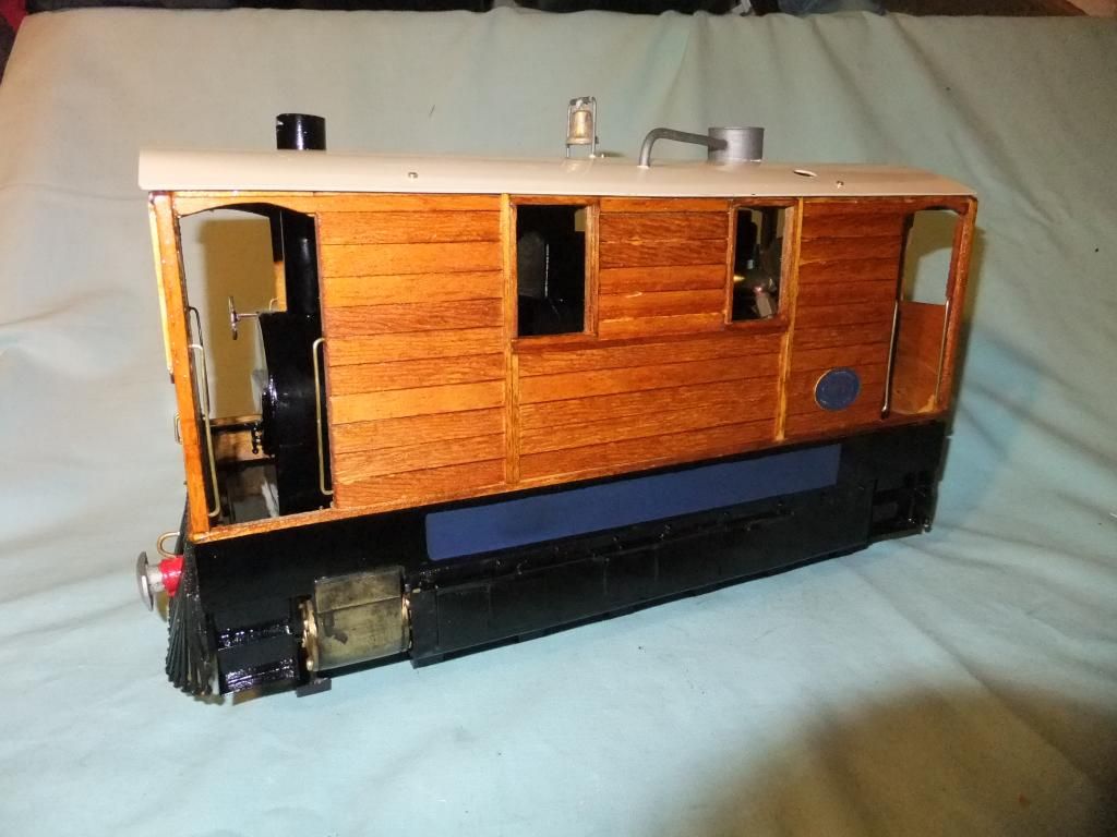
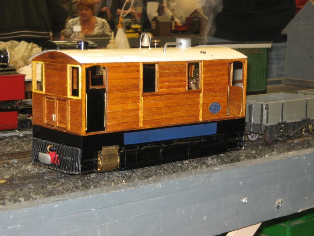
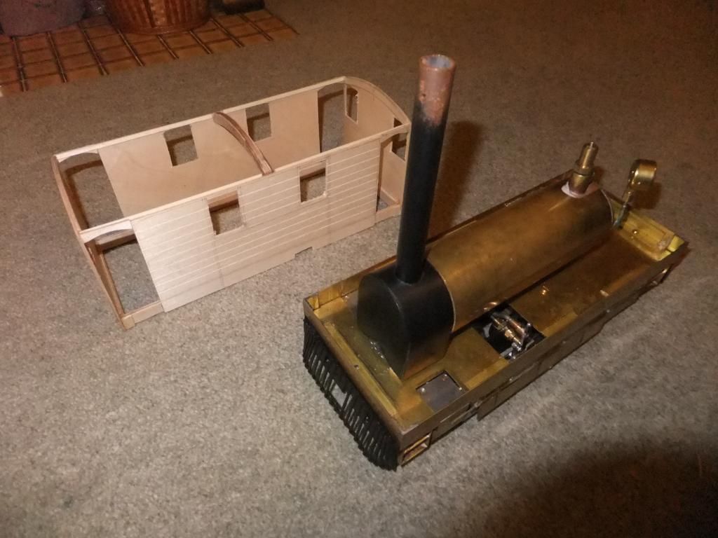
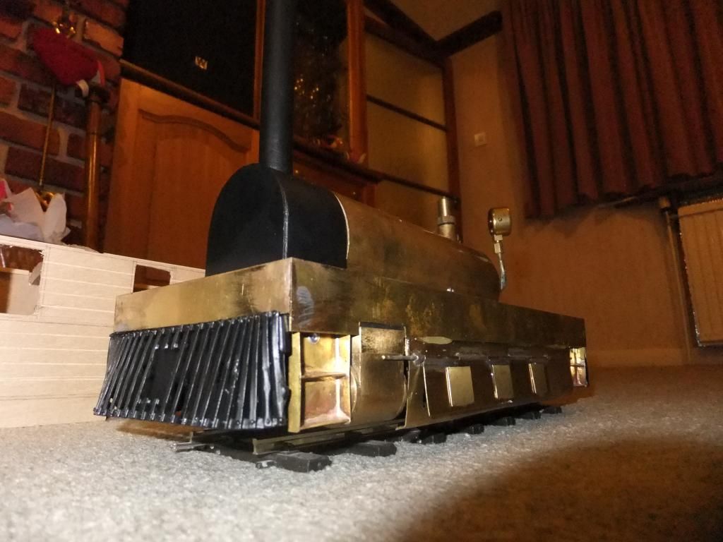
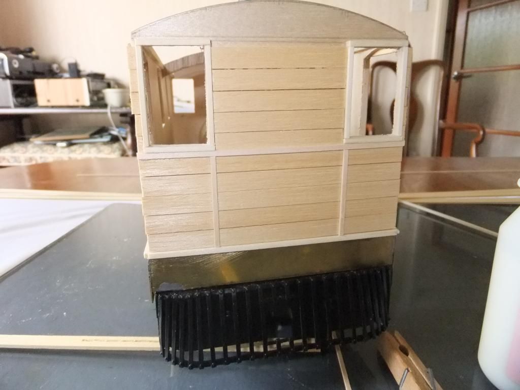
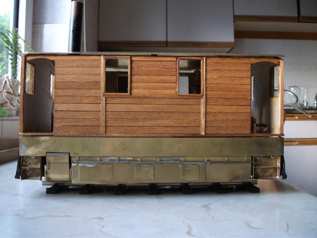
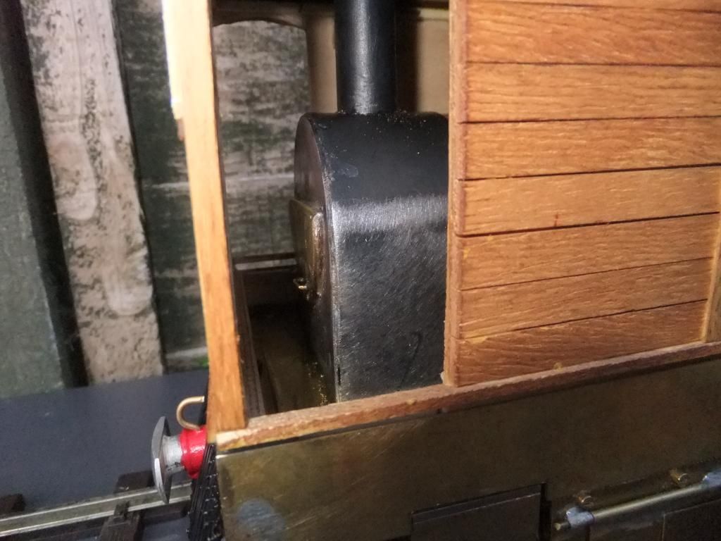
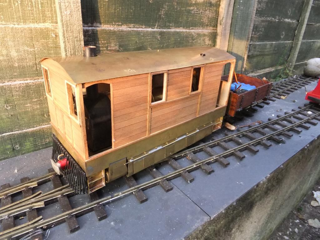
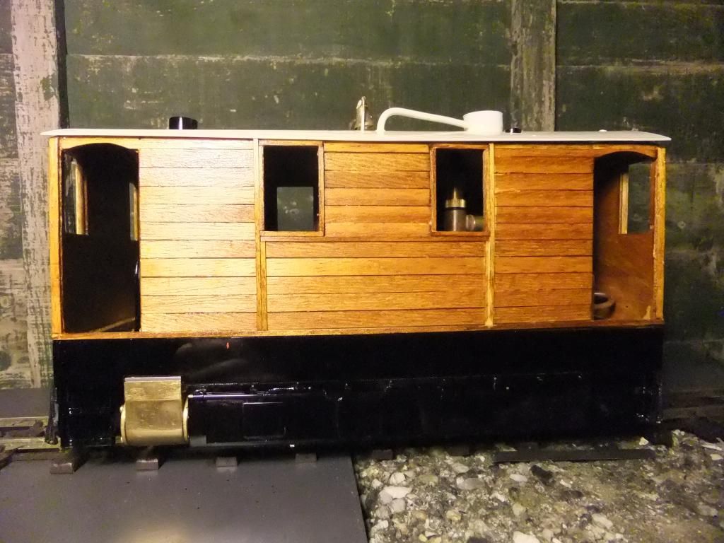
Here is the body. As Keith mentioned in a previous post, and I noticed too, there are a pair of doors adjacent to the smoke box. I added a pair of fake ones to resemble. I popped the buffer in just for good measure too.
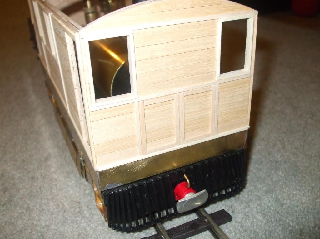
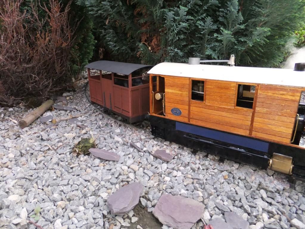
Here is the loco paired with a Brandbright 4 plank wagon. I think it looks like the truck of choice.
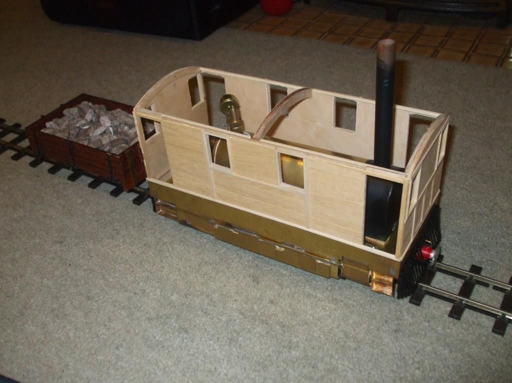
Not too bad for size...
I did find an ok picture showing the J70 with the body and plates off. I can see the controls at the front end! Would you say this has one of those half round smoke box doors? It is difficult to tell.
Tue Jun 04, 2013 6:43 am
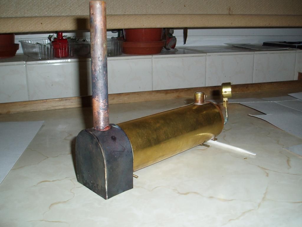
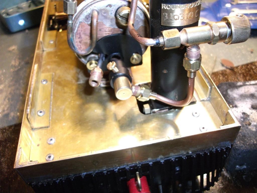
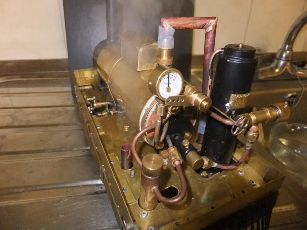
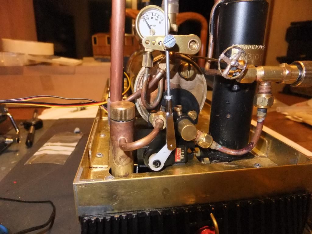
Ahh yes, the black two oval thing does look closer to the buffer beam. I can see that now. It is slightly off centre to the smoke box door. The smaller of the two pipes is the return from the roof for the safety valve blow off. This was diverted to the water tank, also seen here, to dull the sound of that going off. Yes a Westinghouse pump too!
What the larger pipe is for, I don't know. Possibly the exhaust for the safety valve, to the roof?
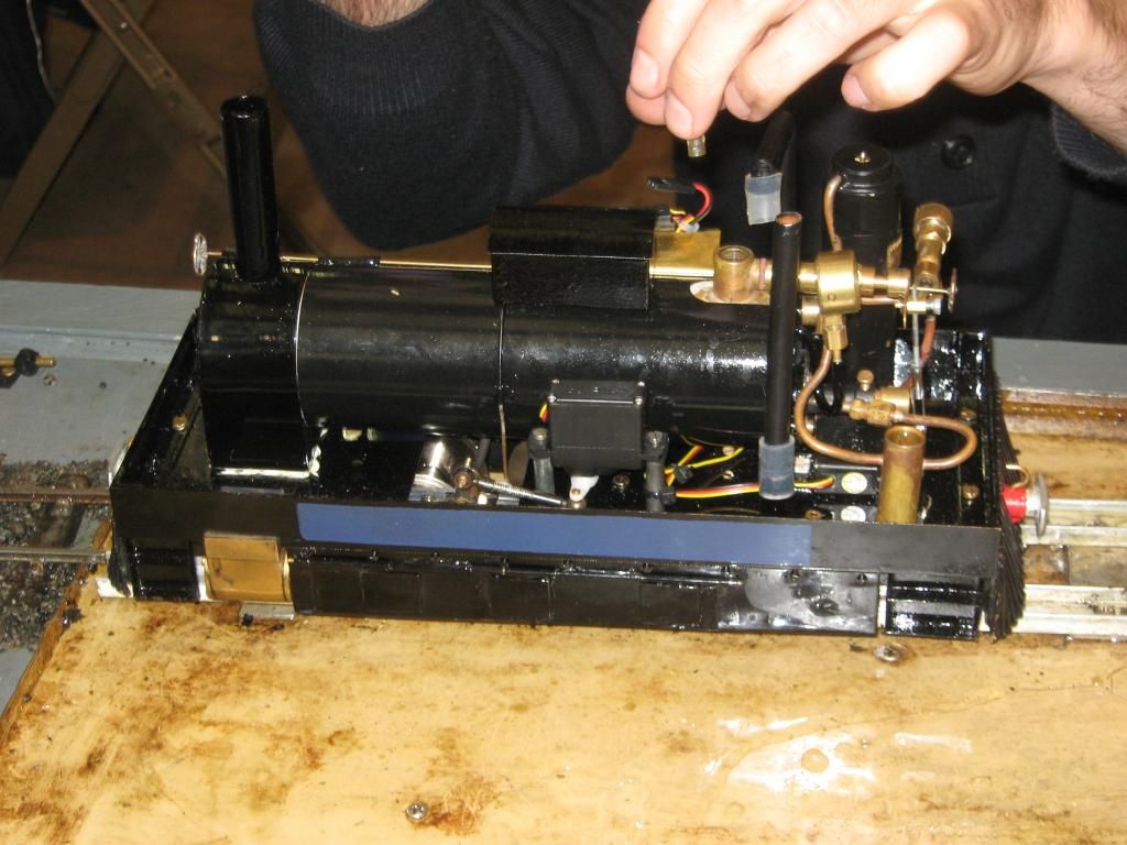
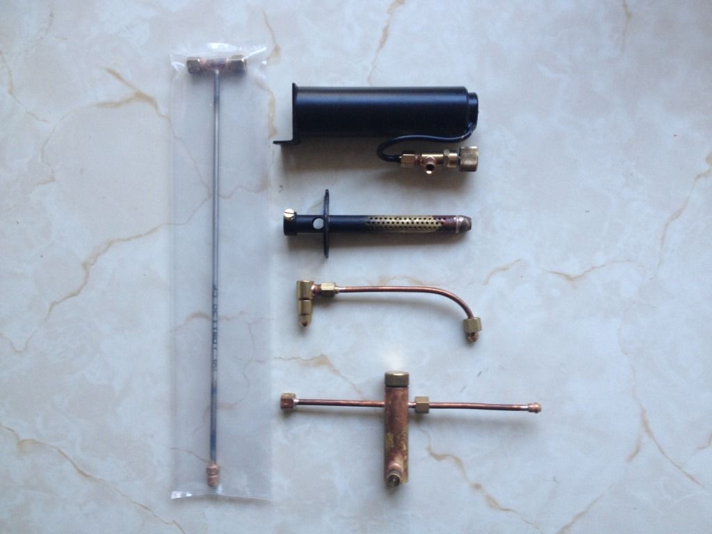
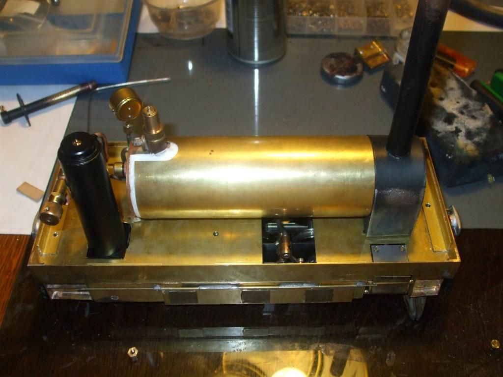
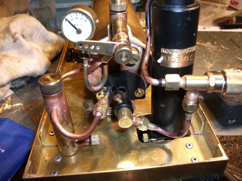
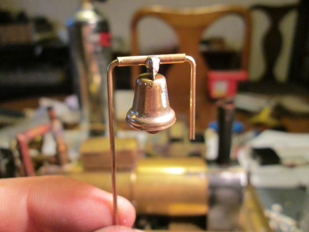
I do have the remaining parts to steam her, see below. I also found this little bell around the neck of one of my daughters toys, she has kindly donated it to this project. It does look about the right size too!
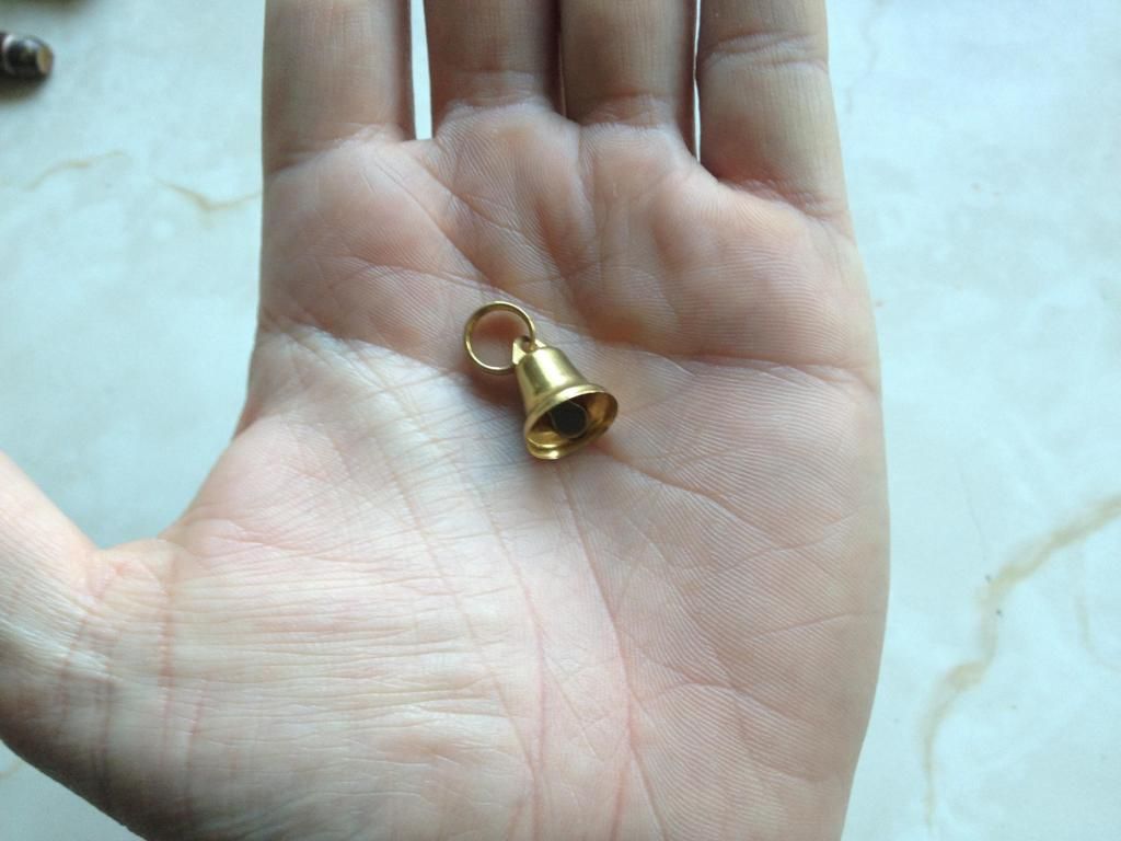
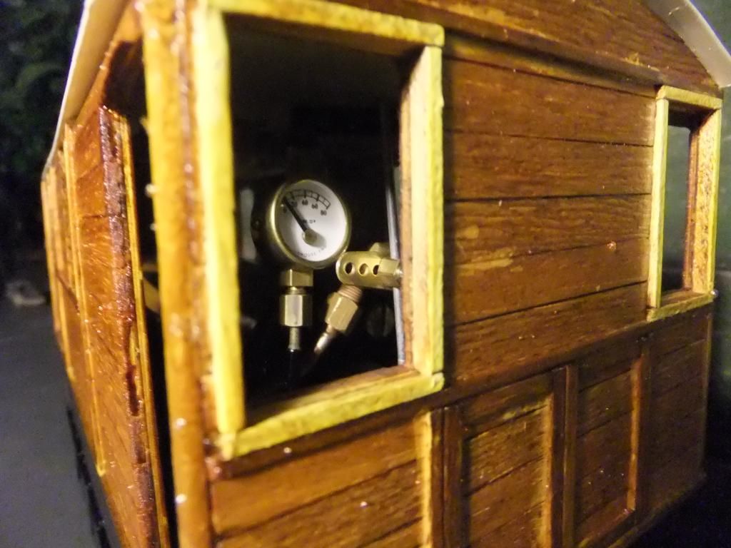
If you notice I already have a pressure gauge on the boiler.
Tue Jun 04, 2013 10:50 pm
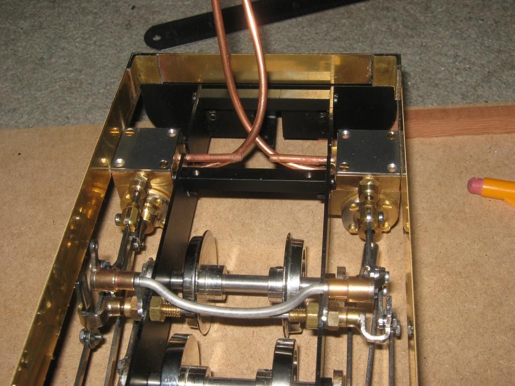
Ok then Guys, I hit a bit of a milestone this evening. I decided to run the chassis up on compressed air. I stripped down the loco back to the chassis and checked, double checked & triple checked my valve and crank timings. They seem to be correct visually, but I am not happy with something. The video says it all. As Pauly said, I put a few drops of light oil into the valve chests and into the cylinder holes to try and preserve the o rings on the pistons.
This is genuinely the first time these wheels had moved under their own power. I am sorry for the poor filming, I was working one handed. Also I must apologise for the poor throttle responce throughout the clip. I only have an air blower that will regulate air flow and the response is very sensitive on the trigger. I did my best.
<object width="800" height="450"><param name="movie" value="//www.youtube.com/v/pibvm7rJpK8?version=3 ... ram><param name="allowFullScreen" value="true"></param><param name="allowscriptaccess" value="always"></param><embed src="//www.youtube.com/v/pibvm7rJpK8?version=3&hl=en_GB" type="application/x-shockwave-flash" width="800" height="450" allowscriptaccess="always" allowfullscreen="true"></embed></object>
The two things I am concerned about after running is the reluctance to go in reverse as well as forwards and the sideways wobble. My Billy doesn't do that, I just don't know where to look to change something. Maybe it is because it is all a little stiff?
Oh, Keith you can just see my Billy locomotive off to one side watching over the progress on the rolling road. Really I had him there to reference crank angles. :)
Thu Jun 06, 2013 11:04 pm
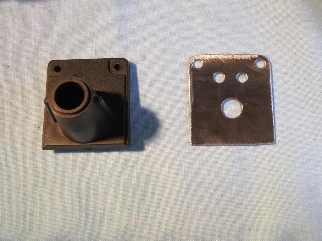
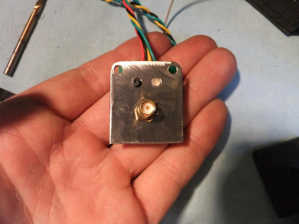
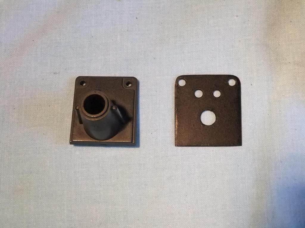
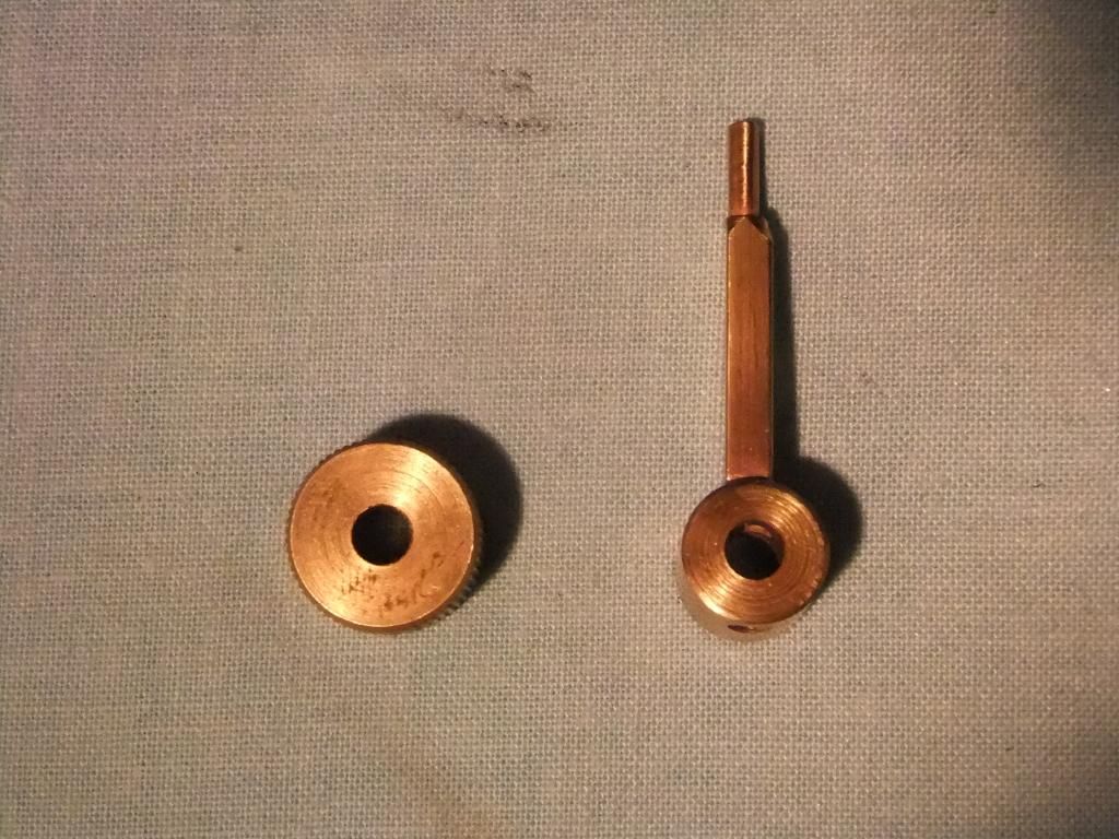
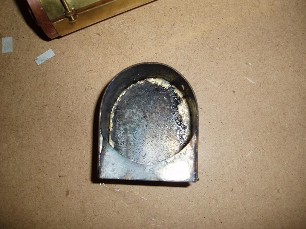
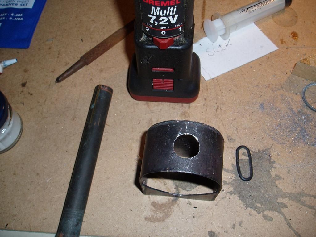
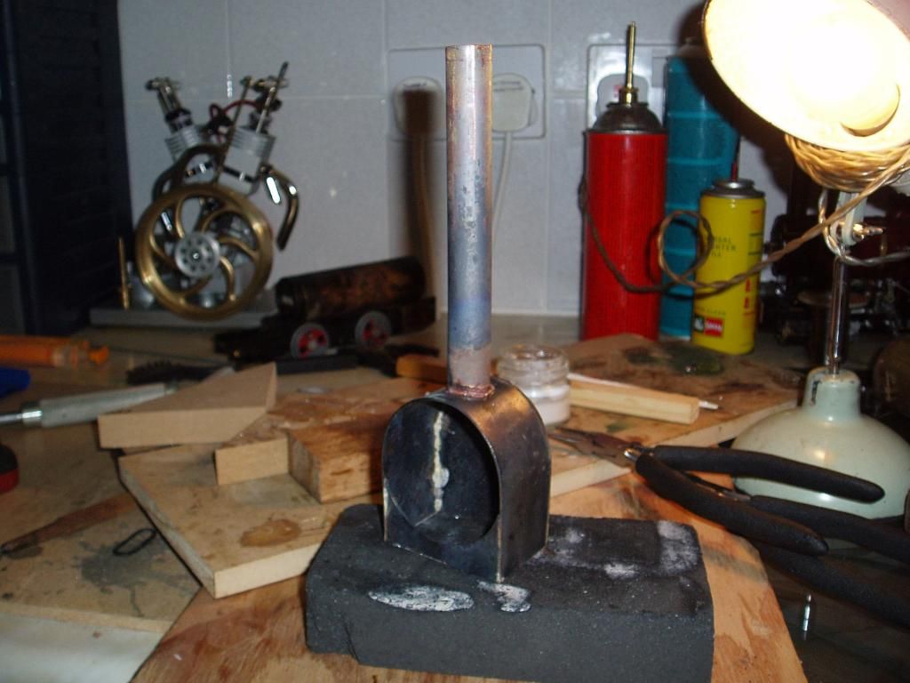
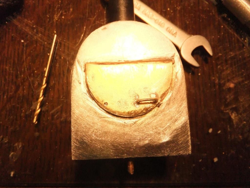
Ok, so I did a couple of things to the smoke box this evening and also fitted the gas tank. For the cab door on the smoke box I was lucky enough to find a large washer with a small hole in the middle and cut it down.
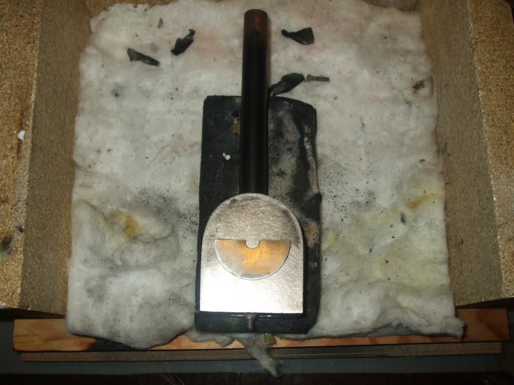
Soldered on
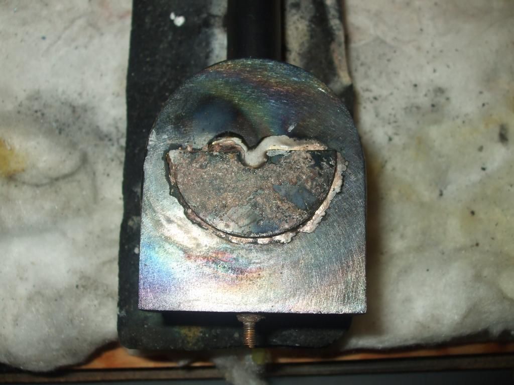
I then cut a brass cover to thicken it up a bit and to cover the remainder of the hole and soldered on
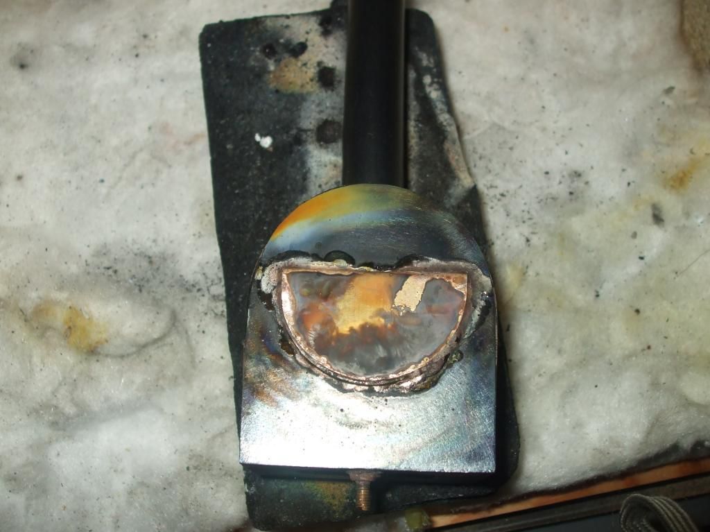
I then sanded that down and tidied up my rough soldering
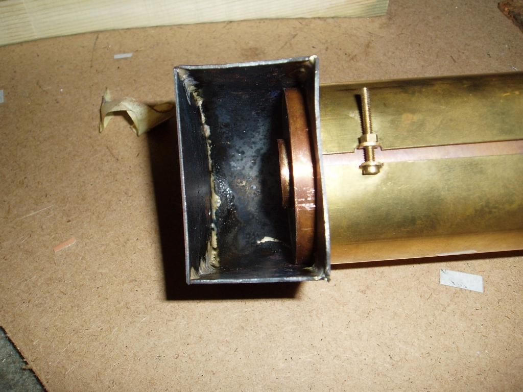
Fitted
And now I have a gas tank
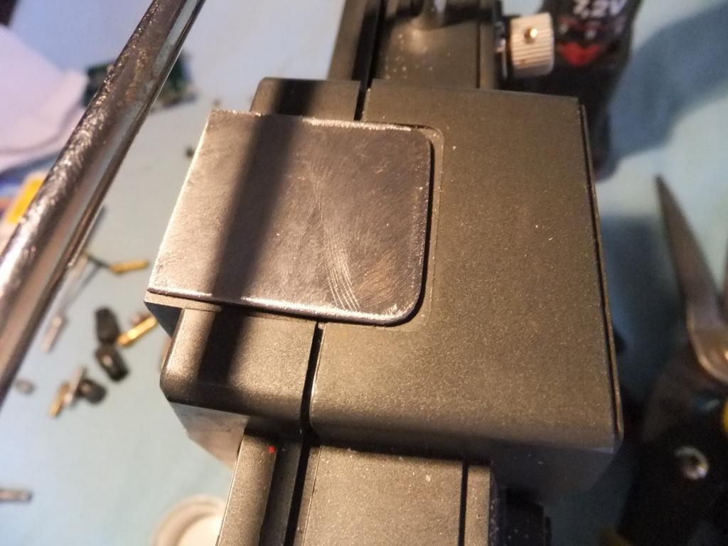
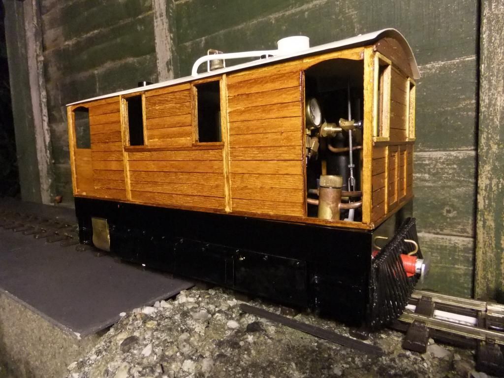
Body on. I thought it would be best to have the gas regulator poking out of the door for easy access. I know how much I alter my 'Billy' one when the loco warms up.
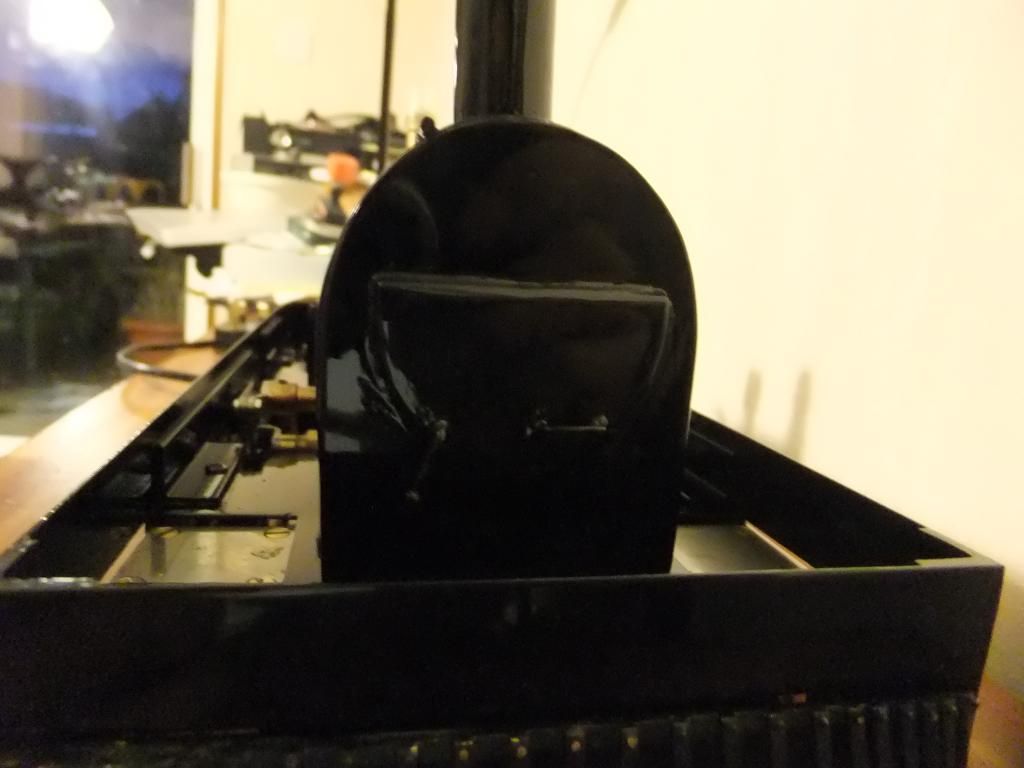
Looking through one of the front window holes
From above
Mon Jun 10, 2013 10:42 pm
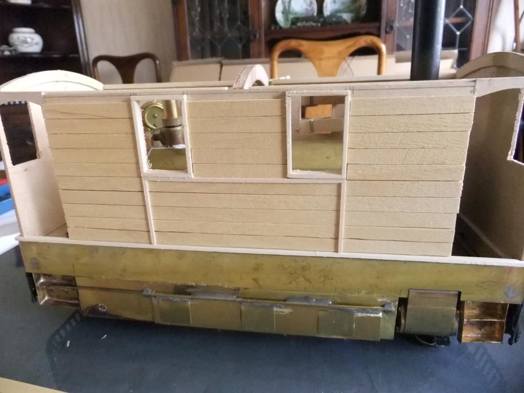
Ok then chaps, I had an hour of so to kill this evening so I got cracking with a bit more of the tram.
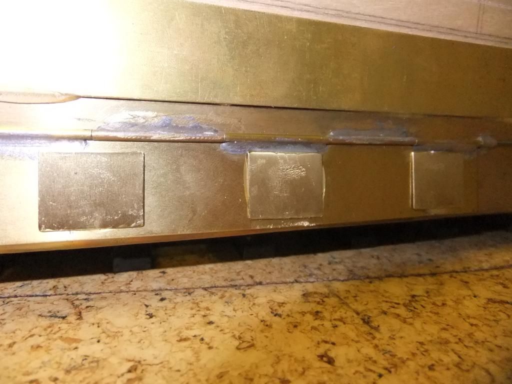
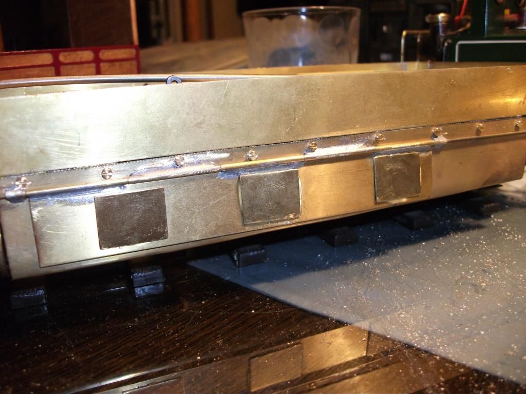
I had managed to get hold of some nice small brass nuts and bolts. I figured that these would serve a practical solution to some of my rivet detail problem. They do look a little ghastly at the moment, but for the purposes of this build they will do. As Keith said, I am into the idea of detail not full blown anal rivet counting (no dis respect intended, I'm just too impatient for that). I am going to add more detail onto the sides of the tub, smoke box and boiler but not just yet.
Here are my new practical solution for holding on the side plates and to add some detail. They were purposely put on a little out of line and wonky to try and build in some character.
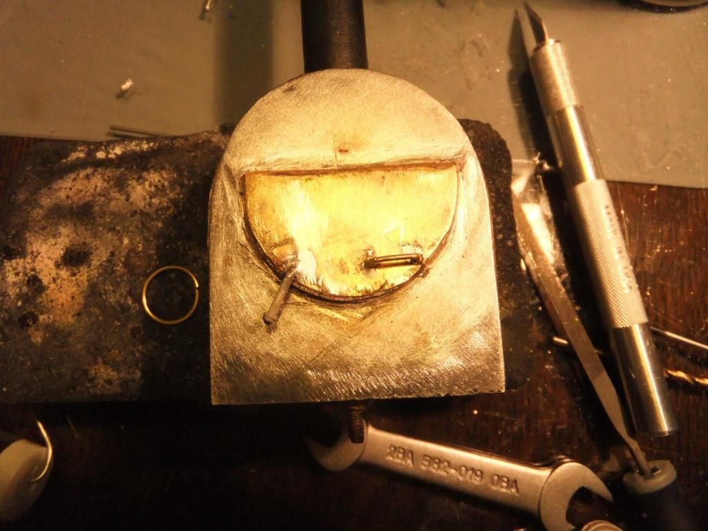
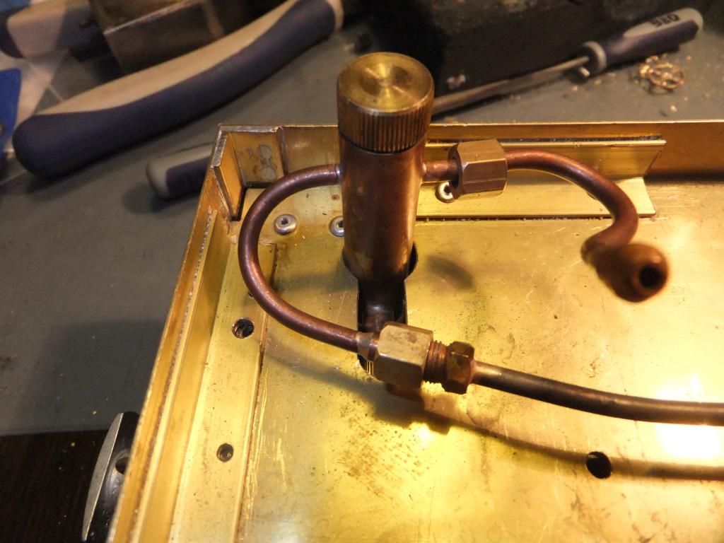
So then I thought I'd get on with getting this tram ready for its first steam up. I made some pipework for the gas tank to jet.
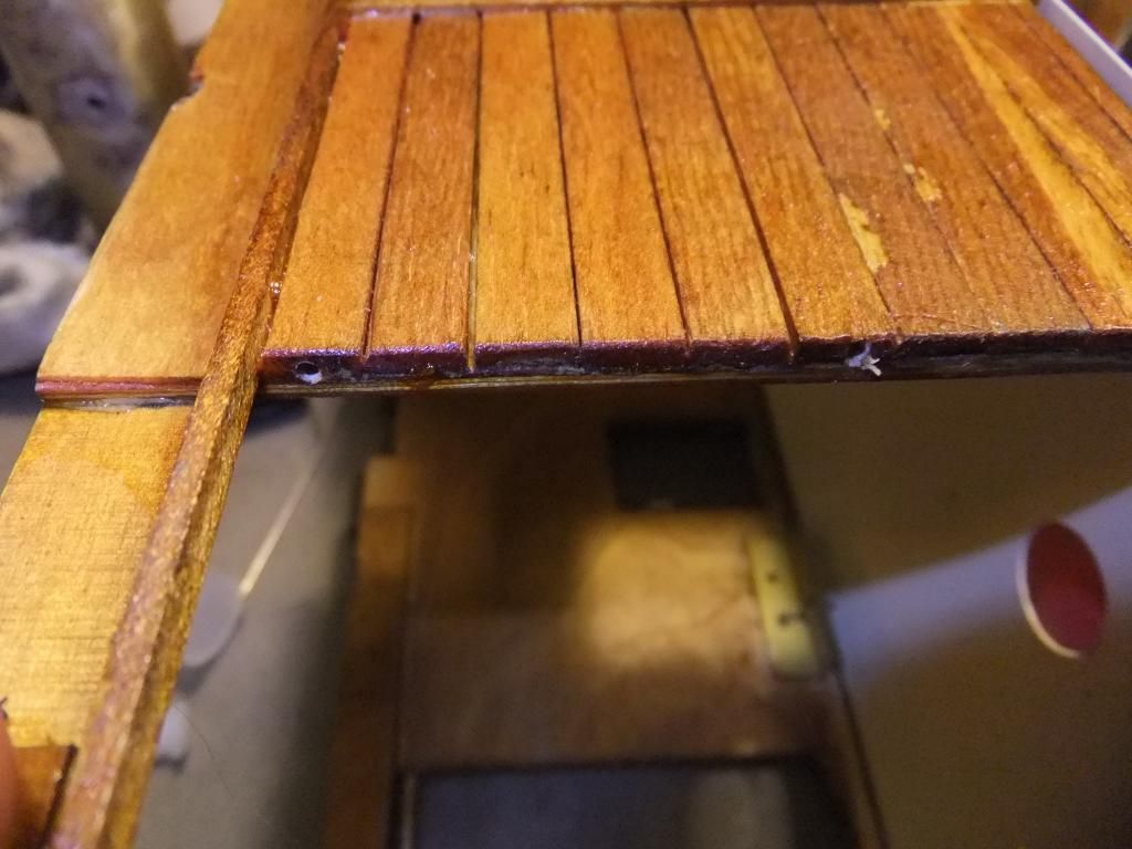
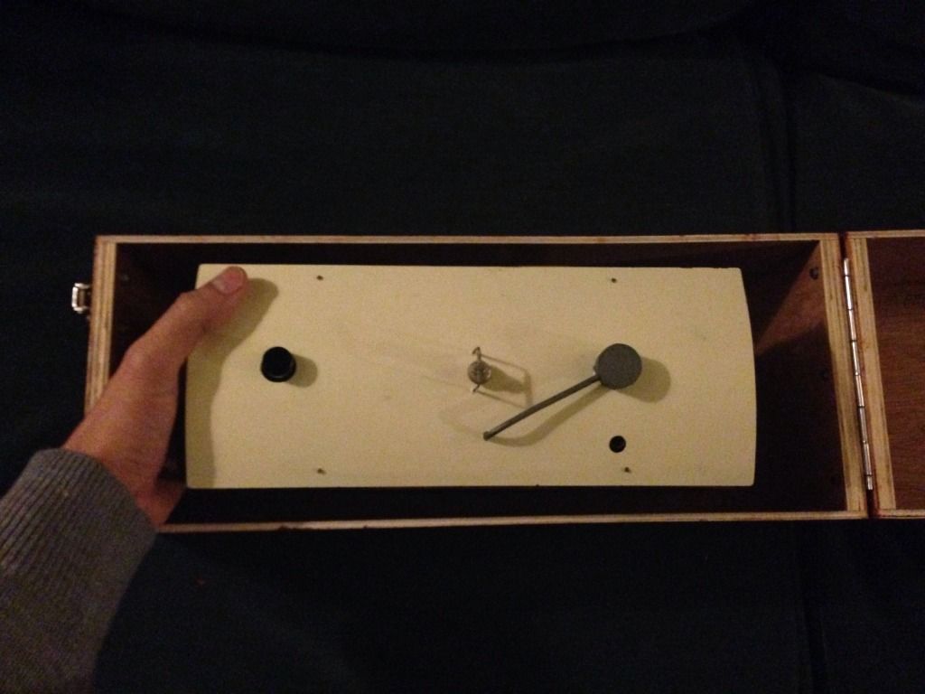
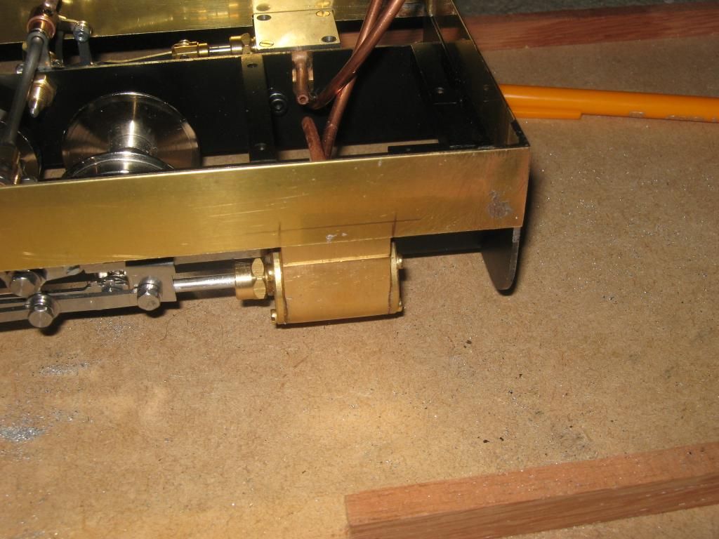
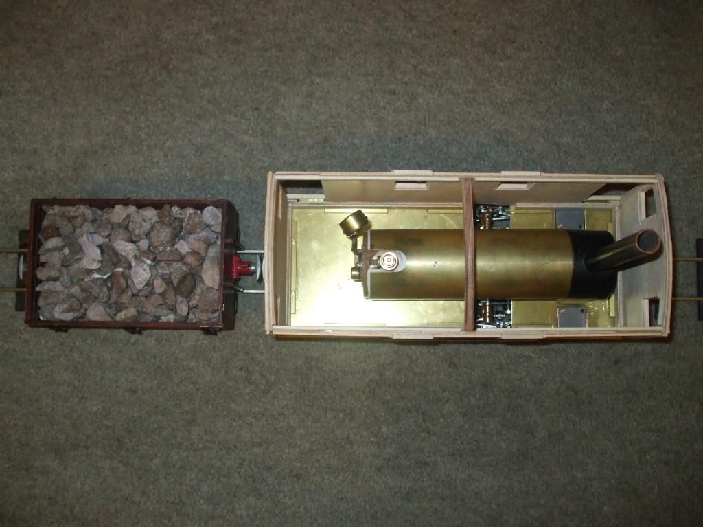
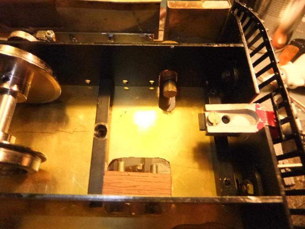
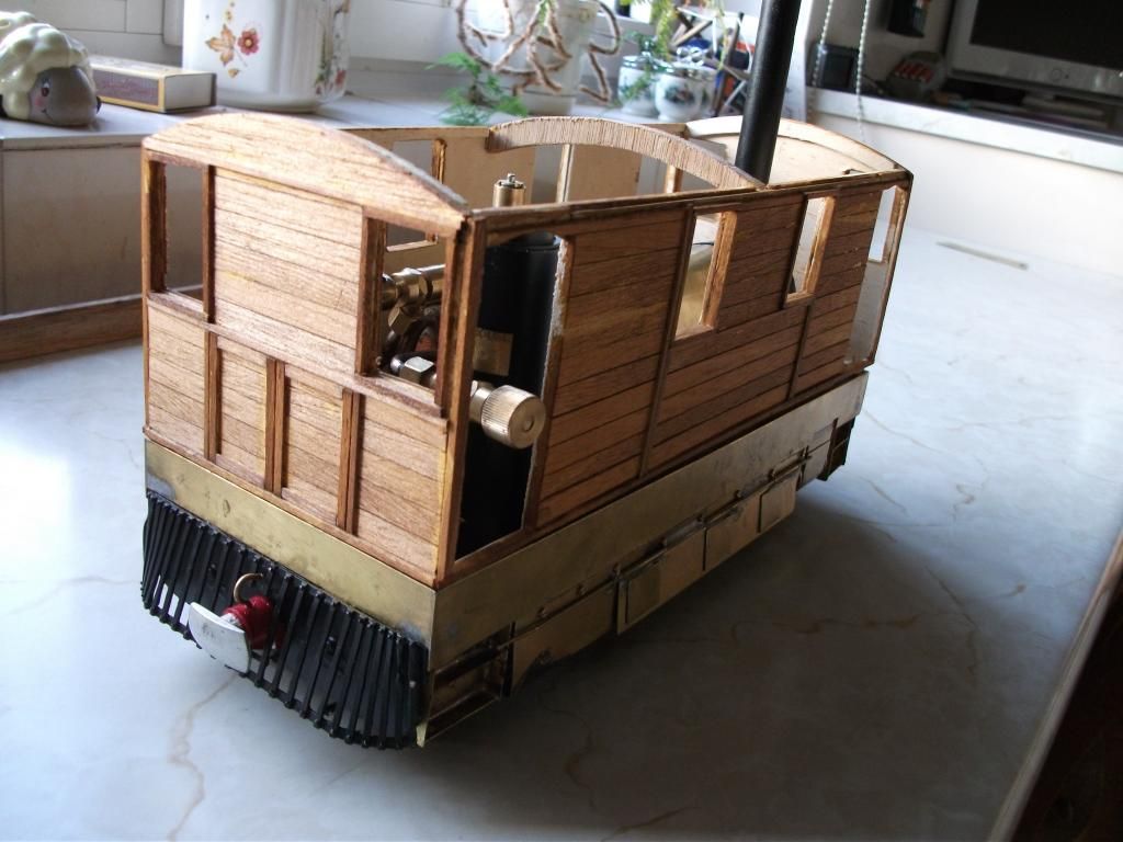
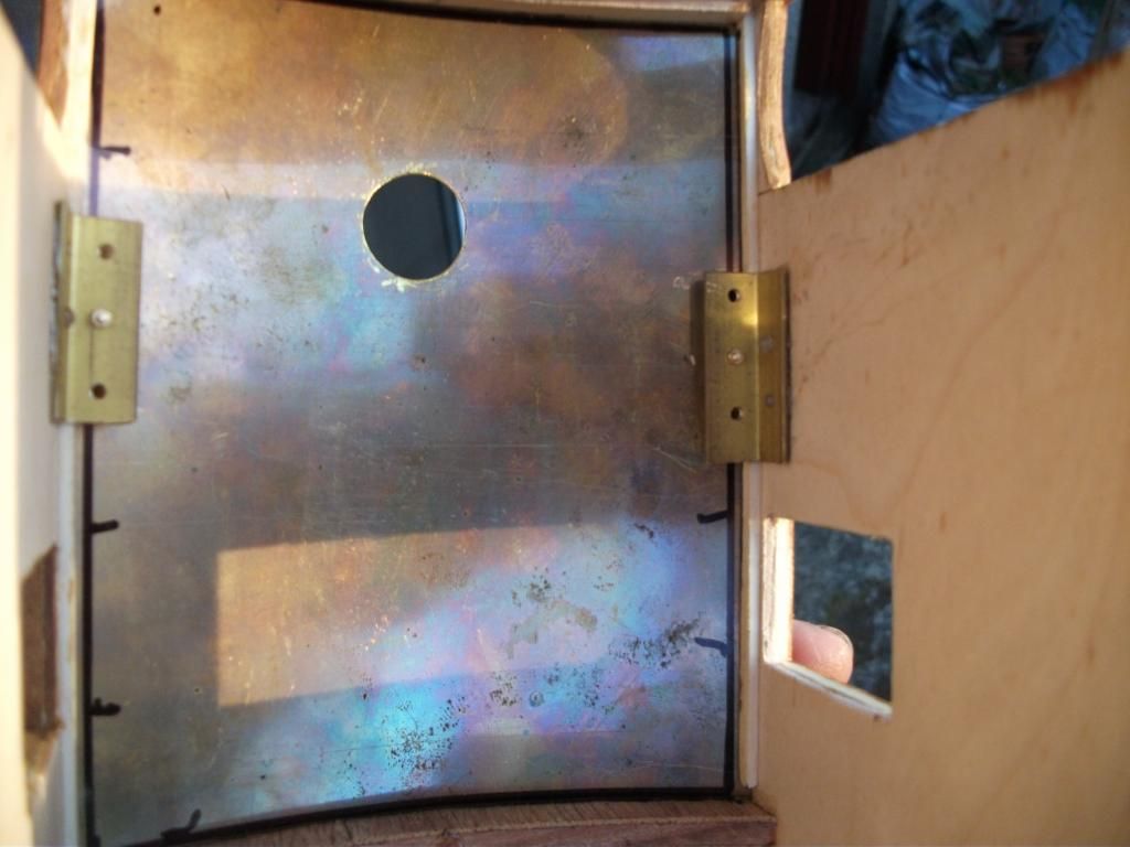
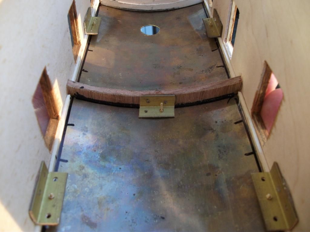
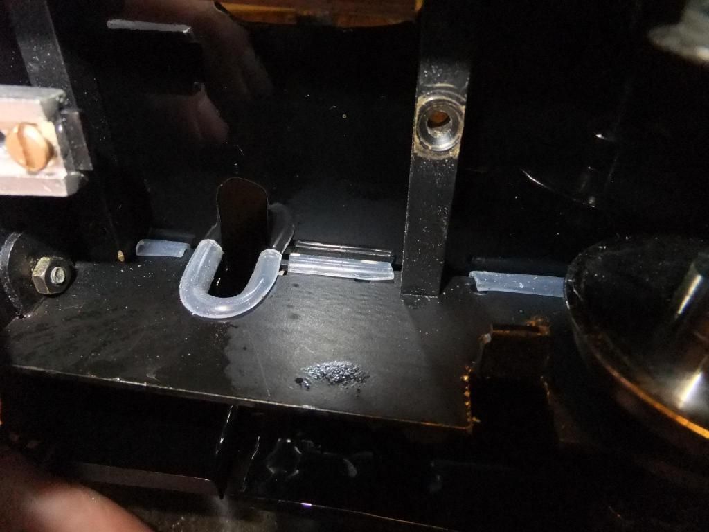
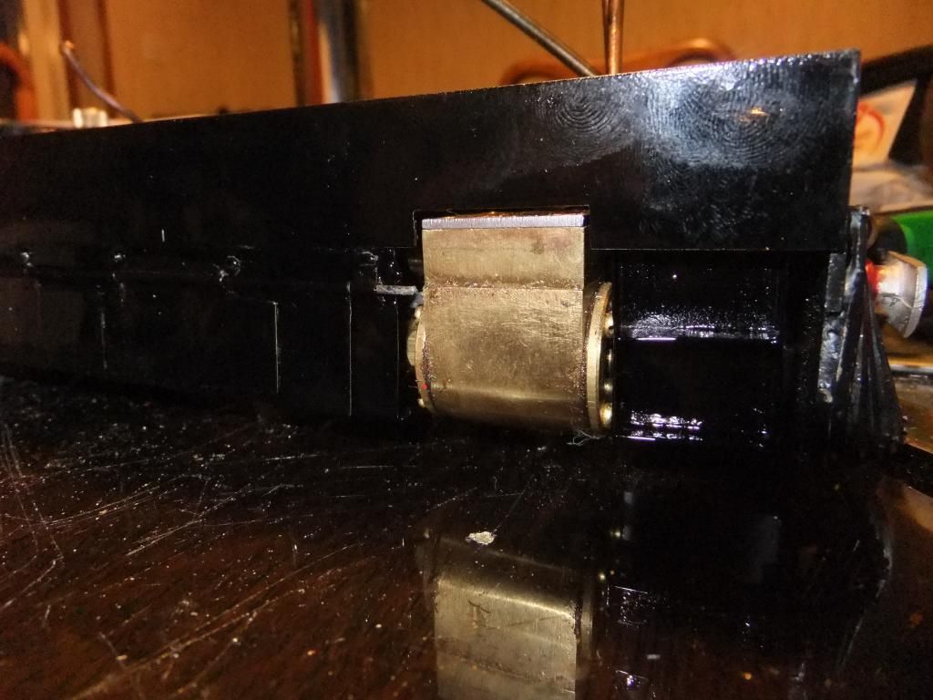
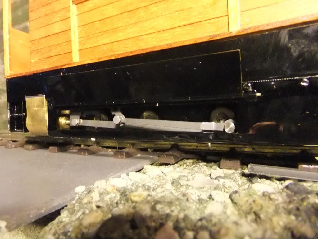
So now I have decided what to do with the lubricator. I am going to put the drain below the floor so I don't have a mess inside the tram. The top will still be inside the cab, just sank through the floor a little. Here it is fitted in the intended spot, above the floor. I am going to fire the loco for the first time tomorrow evening and I can't wait to make holes in the floor and cut the chassis about.
There is lots of room below the floor to allow for fingers to turn the drain screw when the time comes.
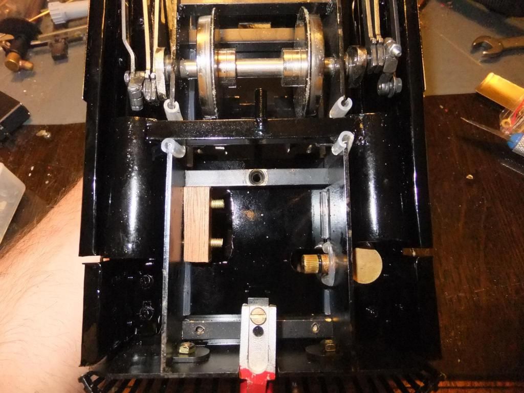
You get an idea of how much room there is shown in the picture below. This image was taken a while ago so does not have some of the things that the loco now does.
Wed Jun 12, 2013 5:58 am
Ok, here we go. The video at last. I couldn't stay up any longer last night, hence the post this morning.
<object width="800" height="600"><param name="movie" value="//www.youtube.com/v/lwgdvfjO6DU?hl=en_GB& ... ram><param name="allowFullScreen" value="true"></param><param name="allowscriptaccess" value="always"></param><embed src="//www.youtube.com/v/lwgdvfjO6DU?hl=en_GB&version=3" type="application/x-shockwave-flash" width="800" height="600" allowscriptaccess="always" allowfullscreen="true"></embed></object>
Thu Jun 13, 2013 10:48 pm
Hi Guys,
Once again, thanks for the kind comments. :)
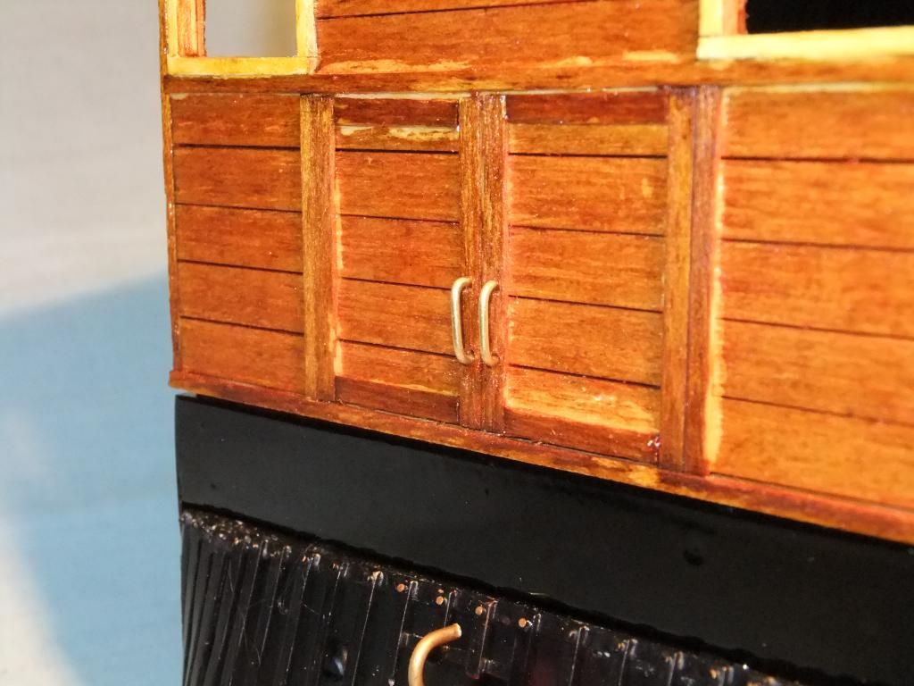
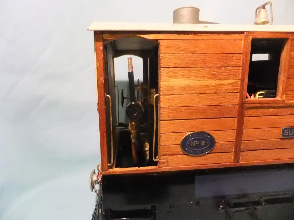
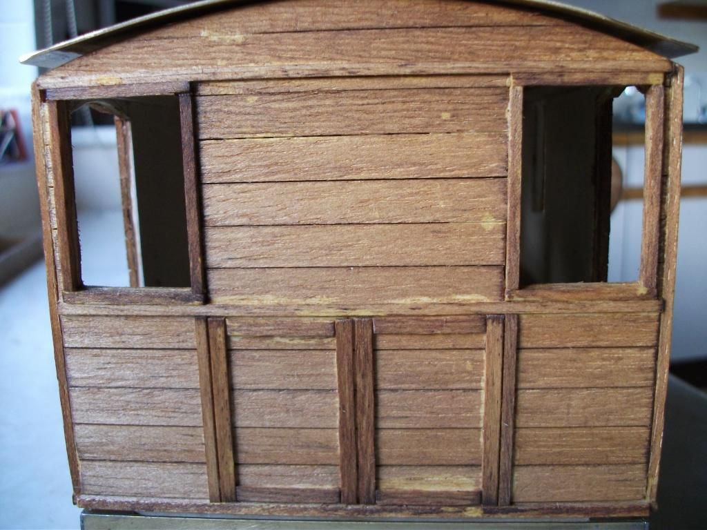
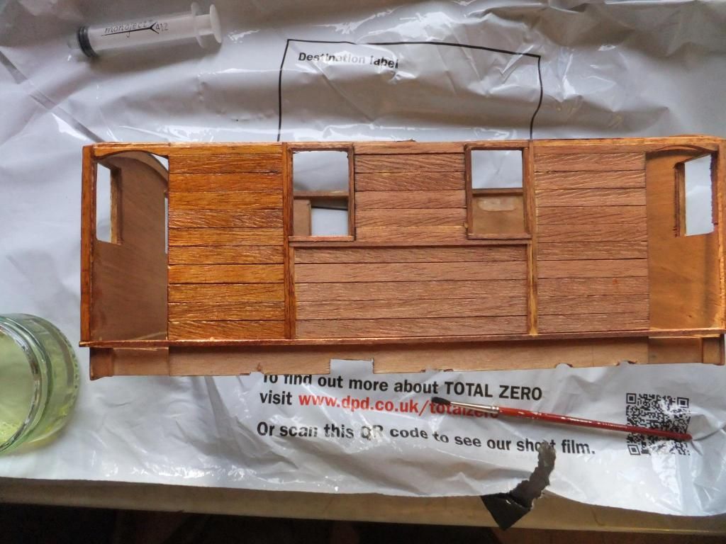
Time for a small update. I have more or less finished the woodwork on the body now. I will now have to start on the metalwork for it, handles, rivets etc. I will post when I have done some of those things. Also does anyone have any advice with regard to what I can use to stain the body, shall I just use wood preservative, or use a wood stain and satin varnish? I'm not sure what would be good with the heat.
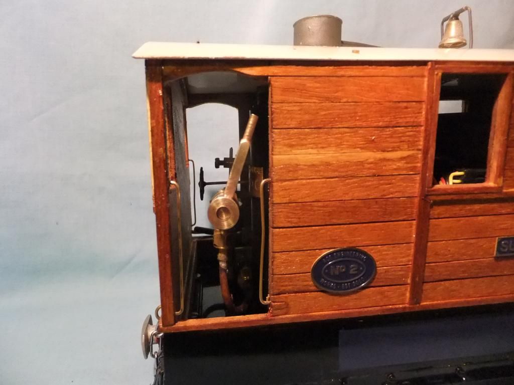
I also managed to get some detail done on the smoke box as previously mentioned. I added a opening handle and also a lever to lock it down with. Looking at the picture below it seems to be just like that. I did zoom in whilst looking on the iPad and it looked a little clearer.
So I did this. I removed the aluminium part of the rivet to reveal the pin, cut the end off and bent it to shape. I thought the head of the rivet made a nice rounded handle end of the driver would not injure himself.
Lift handle in place
Lock lever in place
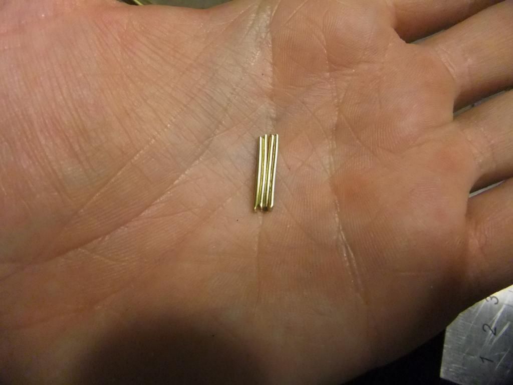
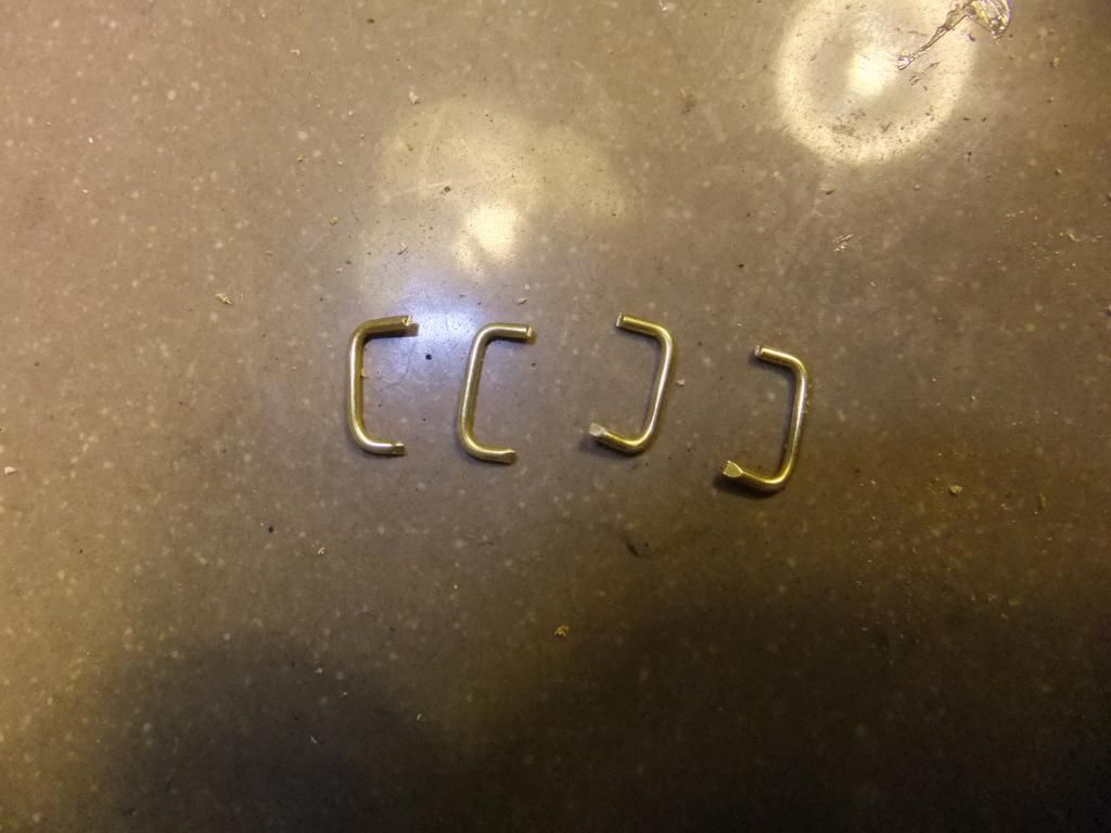
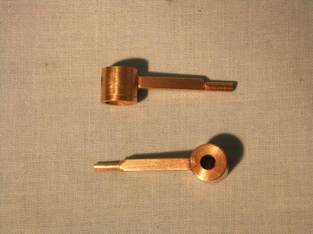
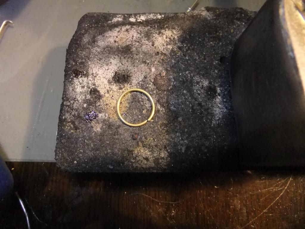
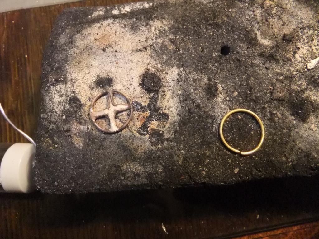
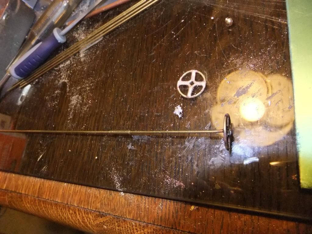
I then started looking for a small wheel for the regulator control, gave up and decided to make one. I used some brass rod wrapped it around a screwdriver head and made a ring.
Cut four small right angles for the spokes
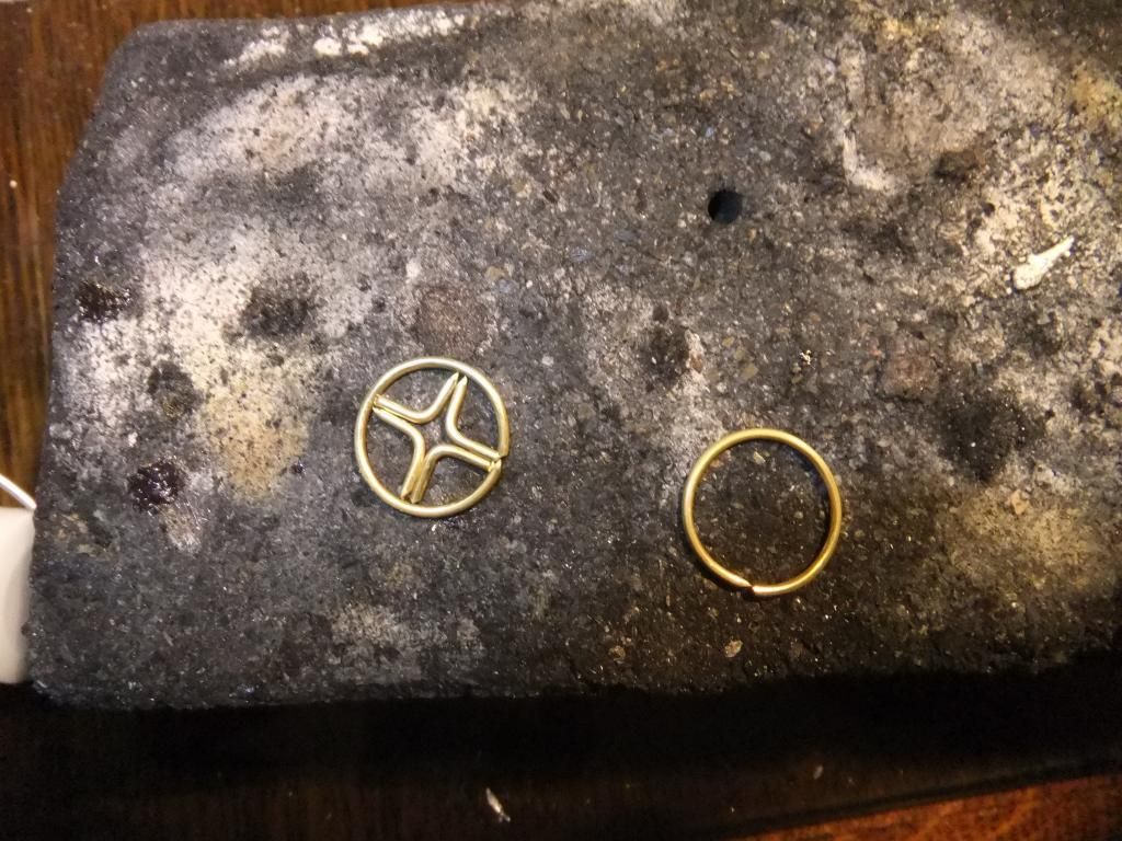
And soldered in
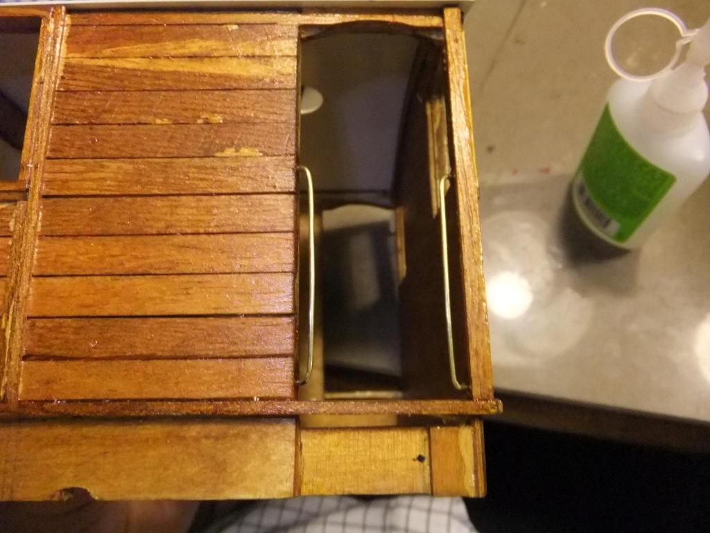
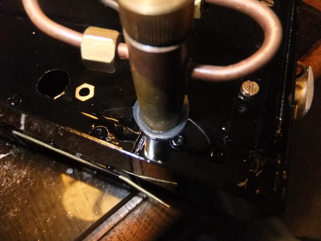
I also fiddled around with the lubricator. I sank it into the floor and mocked it up for the photo. I thought this to be the best place so that I can keep the cab free of oil, thus keeping the wood body free of oil, making it less likely to want to burn. That was my thinking anyway.
From above
From below. There is quite a bit of room there for the drain to be accessed.
Sat Jun 15, 2013 9:18 pm
I think I'll give the GER scheme a go. I mean, If it really does look odd then I can re paint it different colours at a later time. I do want this tram to be different from the average google results.
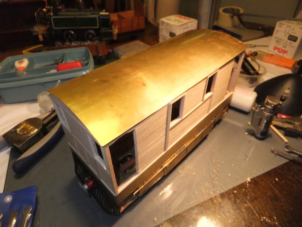
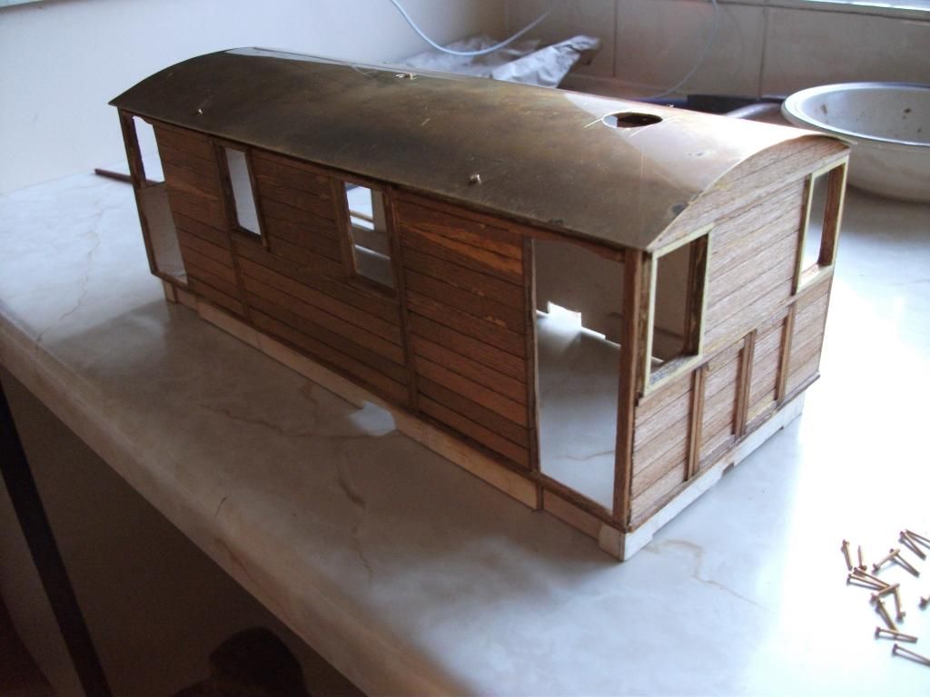
I did a bit more this evening. I thought it long overtime to make the roof. I cut some brass sheet and ran it through the curving tool at work. I did guess the curvature and was not that far out, I just need to bend the edges down a little more. It was quite difficult to do as the tool is designed for larger sheets of steel than my poxy little roof. Lets be honest, this is hardly a transmission tunnel is it? So I had to modify the tool a little to get the rollers a tad closer together.
But here it is, last night I cut the size.
And this evening I had this.
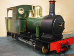
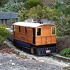
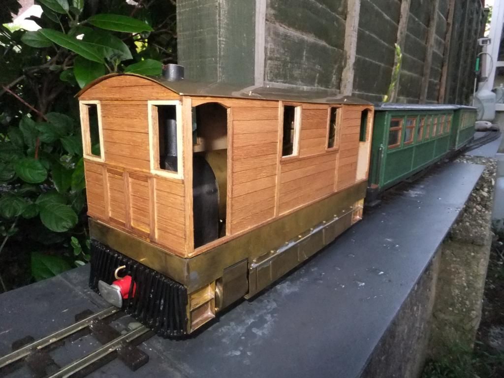
I cut a small hole for the chimney and re assembled the tram one last time before the airbrush comes out for the paintwork. I forgot I had got two andel models 'campbeltown & machrihanish balcony bogie coaches' in the cupboard, so I promptly pulled them out and set about some photos.
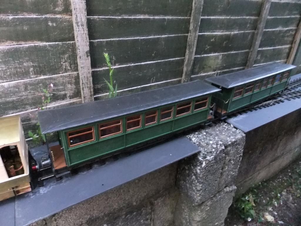
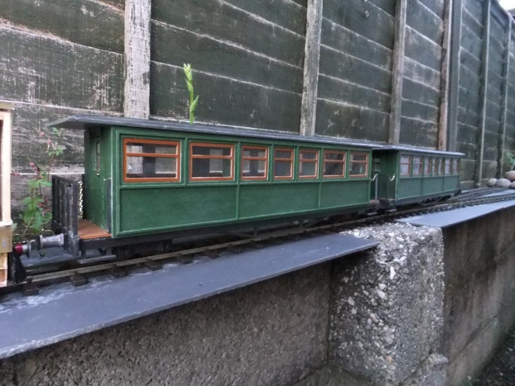
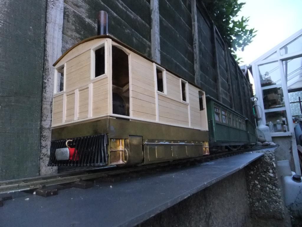
I bought these a couple of years ago because I love the argyll and atlantic locos that ran them. I was going to get an atlantic from roundhouse, but they inconveniently decided to discontinue production, swines... :(
When the time comes I am going to incorporate the campbeltown & machrihanish line into my layout, along side the wisbech and upwell.
So for now I am left with having to speak nicely to the refinishers at work to mix me up some commercial vehicle colours of my choice. I have the colour chips with me now, I just need to decide. Looking at the photos, the insides of these locos seem to be the same as the outside, colour wise. I was going to do the inside of the tub, (cab floor) black and teak stain the wood inside and out, sound ok?
Tue Jun 18, 2013 10:04 pm
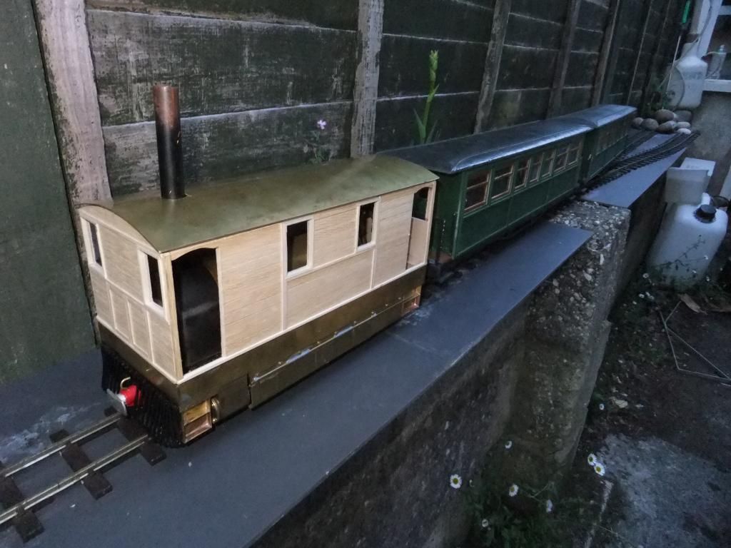
Hi Guys, I did a little more this evening. I wasn't going to post any pictures of the tram until I had it all painted and detailed, but this is a quick one before the last bits before that. Unfortunately you are going to see the stain in which I chose for the wood colour. Its not too orange like the photo above too, but I have taken on board some of your comments about the scheme that I am going to use. I have decided to make one that I think fits my mind and take some of (in my opinion) the best bits from each scheme that these locos used.
A couple of nights ago I stained the body of the tram.
And this evening I made up some small brackets and fixed the roof to the body. I had to do a little more fiddling with the roof to make it fit better.
I couldn't resist a short video too with the two coaches shown above, enjoy.
<object width="800" height="600"><param name="movie" value="//www.youtube.com/v/2FFMUjTvPcI?version=3 ... ram><param name="allowFullScreen" value="true"></param><param name="allowscriptaccess" value="always"></param><embed src="//www.youtube.com/v/2FFMUjTvPcI?version=3&hl=en_GB" type="application/x-shockwave-flash" width="800" height="600" allowscriptaccess="always" allowfullscreen="true"></embed></object>
And in case no one noticed, I cut the chimney to length too.
Thu Jun 20, 2013 10:30 pm
Thanks for the comments Guys.
First things first, Yes I am going to r/c this loco. At the moment my budget is running a little low and is awaiting replenishment so servos and receiver are quite low down on the to purchase list. I am still amazed that the bloody thing runs!!
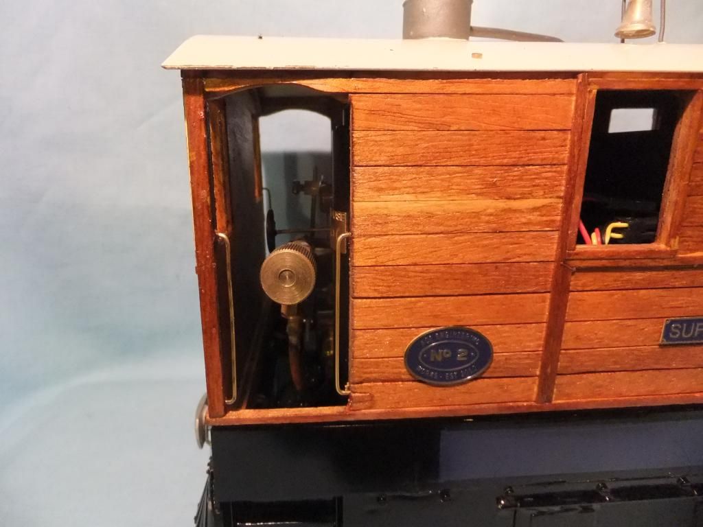
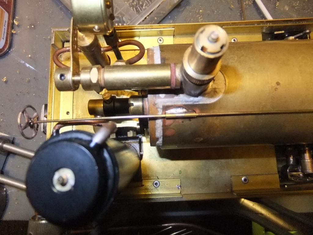
I keep threatening to paint this loco but I have been way laid again with building detail. Remember I made those regulator controls for the smokebox? Well I fitted them tonight.
First I used some brass rod and tube, the same as for the access flaps on the skirts, and soft soldered directly to the boiler cover.
A little piece of tube
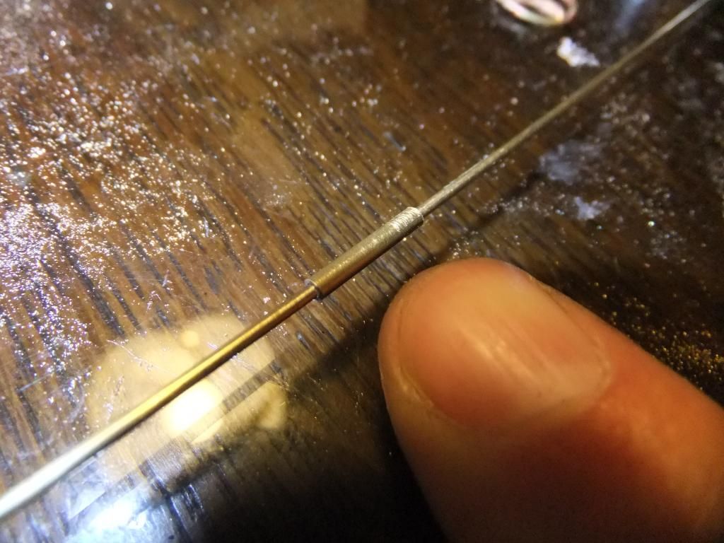
Soldered on
The last piece of tube at the smokebox end is a little longer so that the smokebox control can be removed for assembly / disassembly
To keep the brass wire in place I put a slight bend at the end of it to keep the fit tight in the last piece of tube.
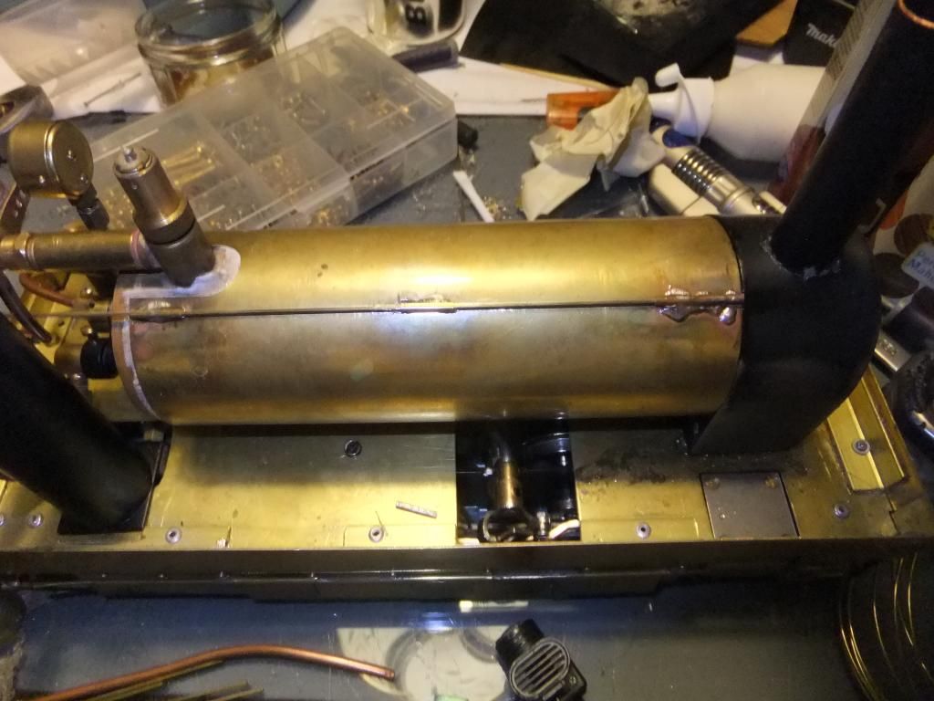
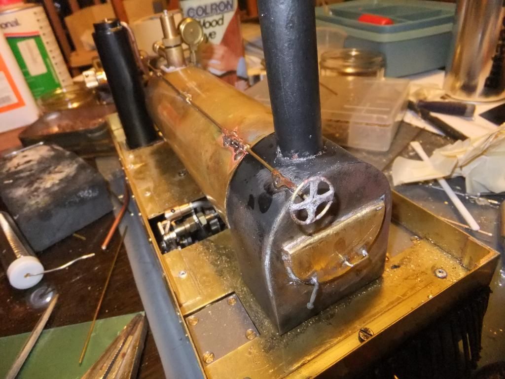
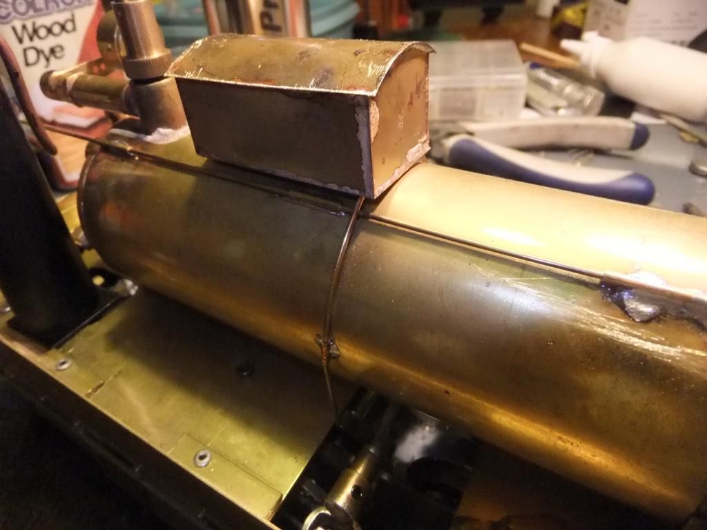
Then I started on something else, can you guess what it is?
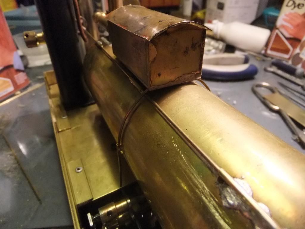
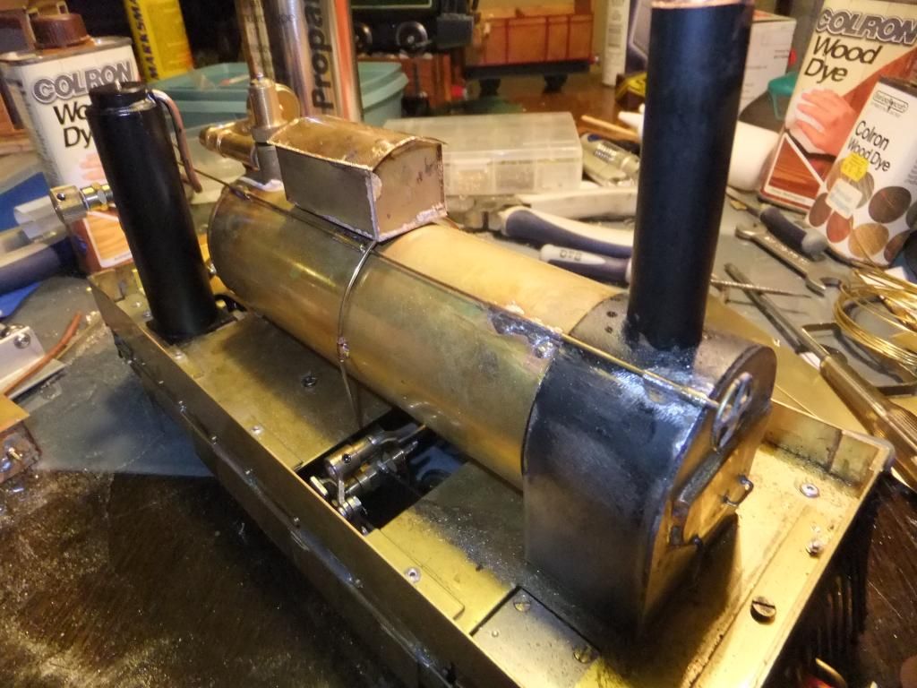
Well I'm sure you all know, its my little sand box. Fixed to the top of the boiler by the same method as the controls.
Fake tubes soldered to the bottom of the box
And sat in place. I will more than likely put a small blob of silicone/polyurethane sealer under this to keep it in position once all painted up. I put the lid on a bit off skew like it was carelessly thrown on or shaken off by the last journey
And both new details together.
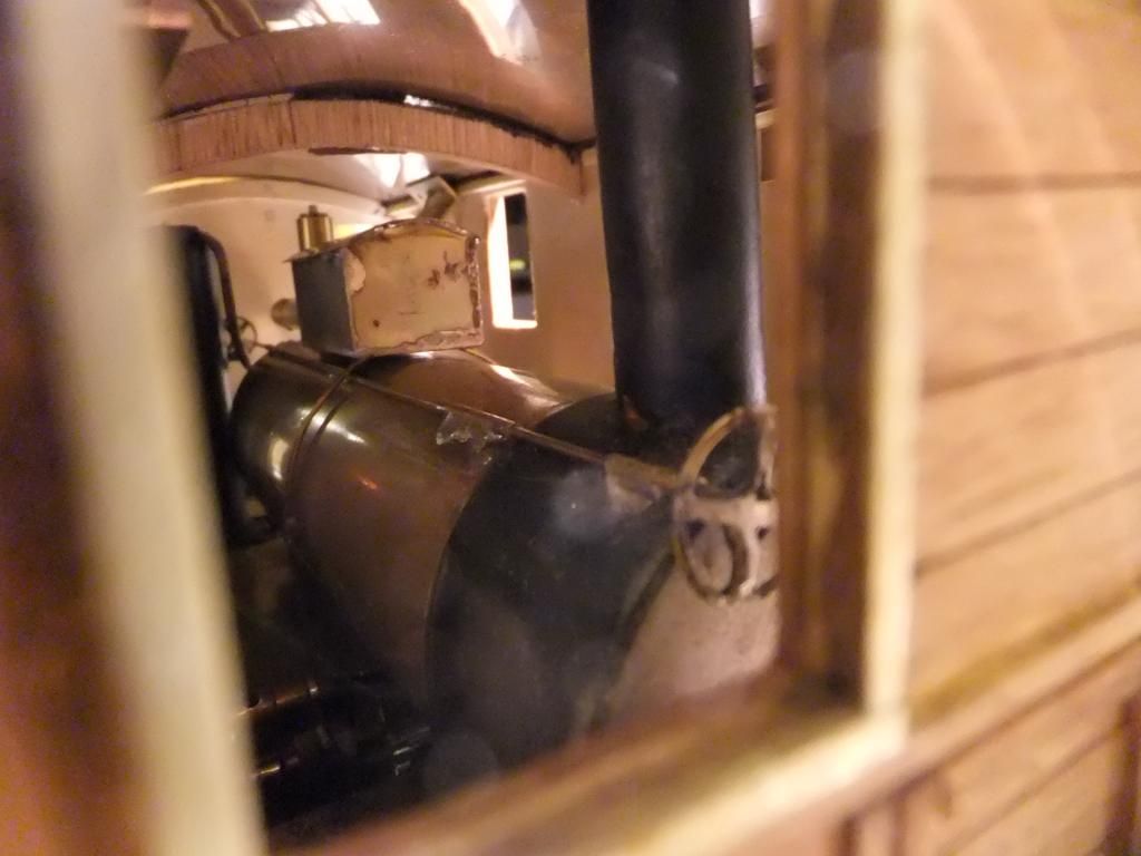
A quick nose through the front window.
And just to add I am going to make a condenser / silencer for the safety valve. I don't want it blowing off straight out of the roof of the cab, that to come.
Wed Jun 26, 2013 10:52 pm
Hey there Guys,
Sorry for the break in progress. I have been doing some playing just lately, rather than building.
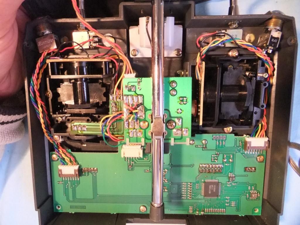
I have been pondering over this last practical solution for a while. My problem is, I have just noticed how little room I have under the body. As you know I want to R/C this loco. I have precious little space for the regulator servo, a micro one is required. The reverse control one will be fine with a mini servo. Batteries and receiver I have pencilled in locations. so that leaves me with the problem of the safety valve exhaust.
The original locomotive safety valve exhaust was taken through the roof and back into the body, possibly into a condenser tank and somewhere. I am not sure. So I currently await the arrival of the new book Pauly found so I can have a good look at it.
So I have come up with the solution below. I am going to make dummy pipework on the roof as per the real locomotive. It has to be dummy because of the size of the pipe involved. It would be too small to manage all the steam from the safety valve at once. So I have decided, as I have enough room, to take the safety valve gasses from inside the cab, to a condenser and out of the loco.
I decided to utilise some of the under skirt space I have to fit the condenser tank(s). The problem remains of where the safety valve gasses actually escape from on the real loco. It goes out the 'valve, through the roof, back down inside to the condenser and then where? Back up the roof again or exit somewhere else? I just don't know at the moment.
I have fallen on two avenues of which depends on my findings. To exit the gasses through the roof or pipe them over to the smoke box and out the chimney.
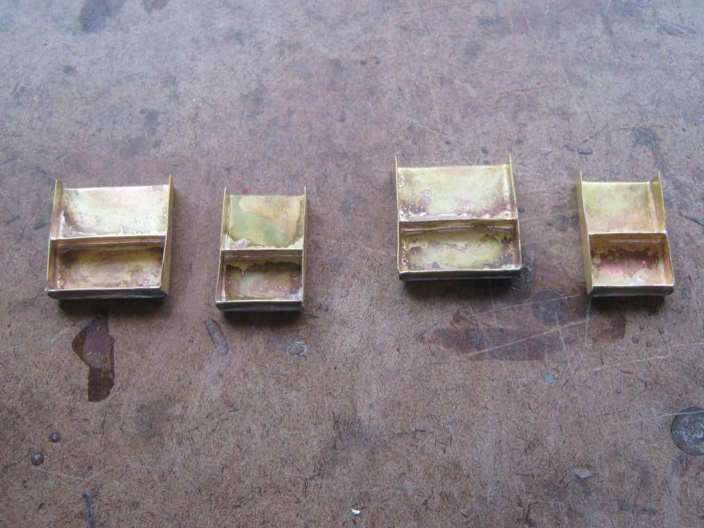
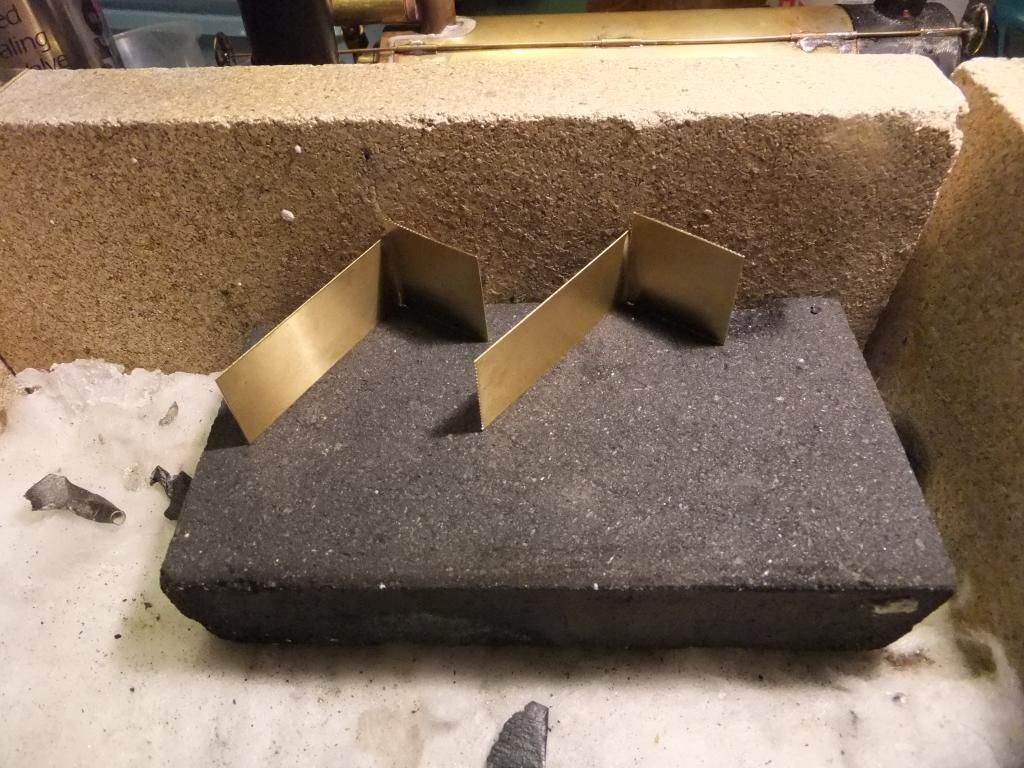
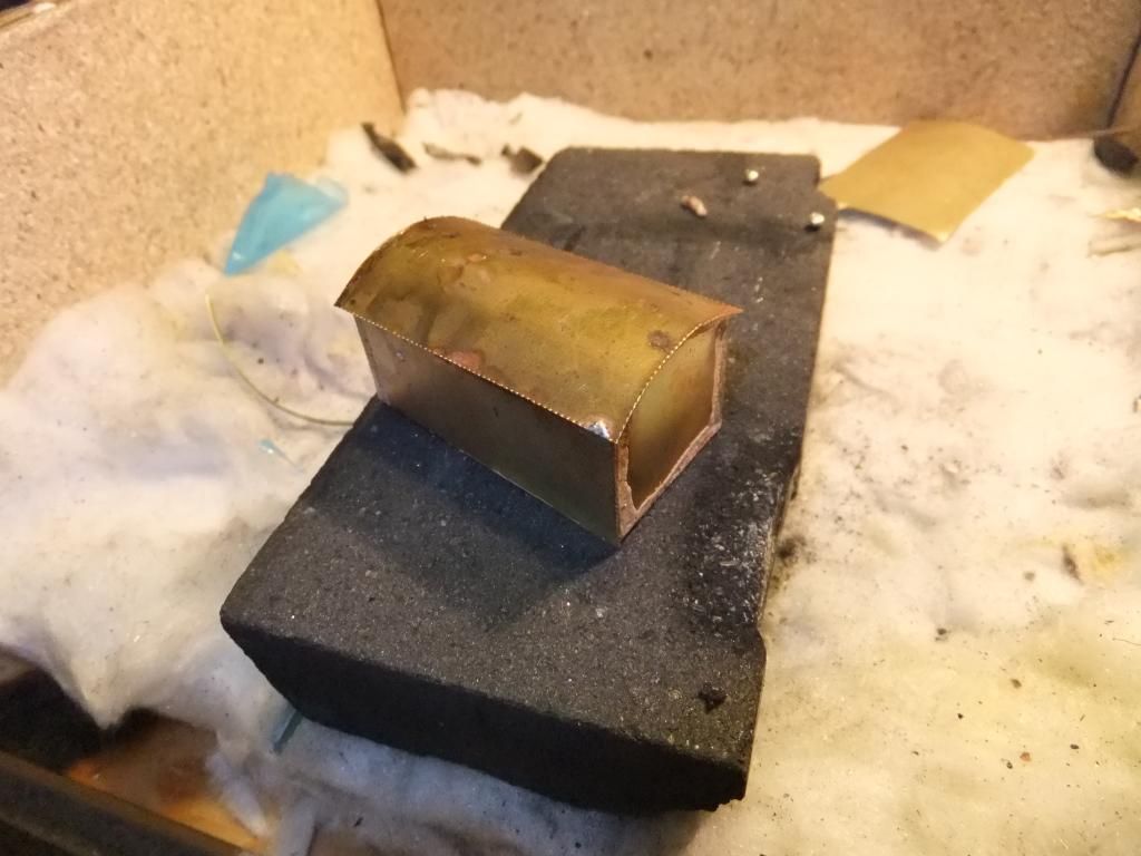
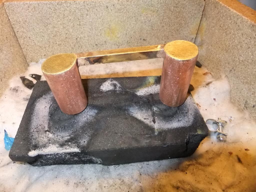
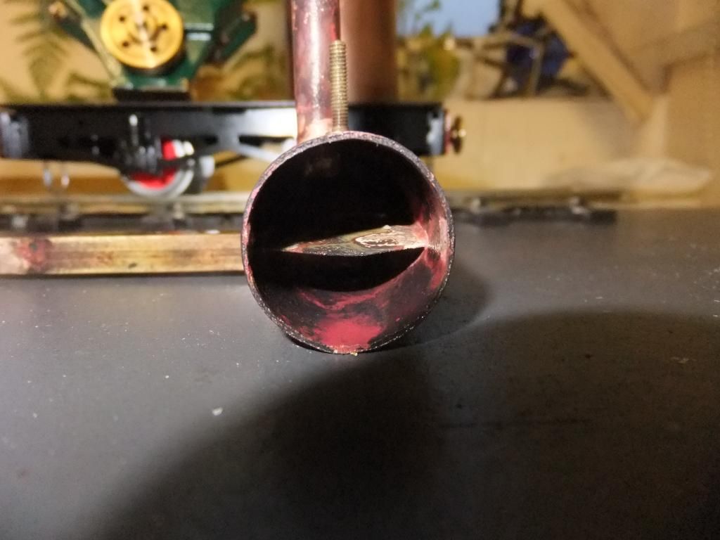
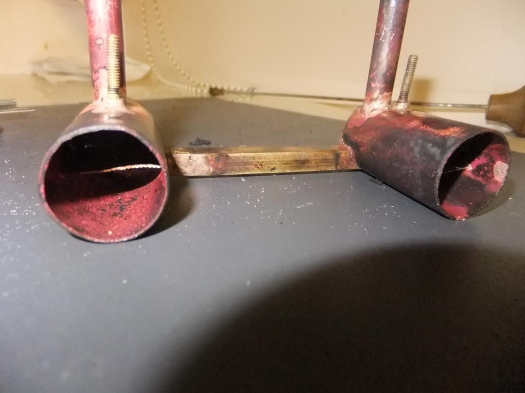
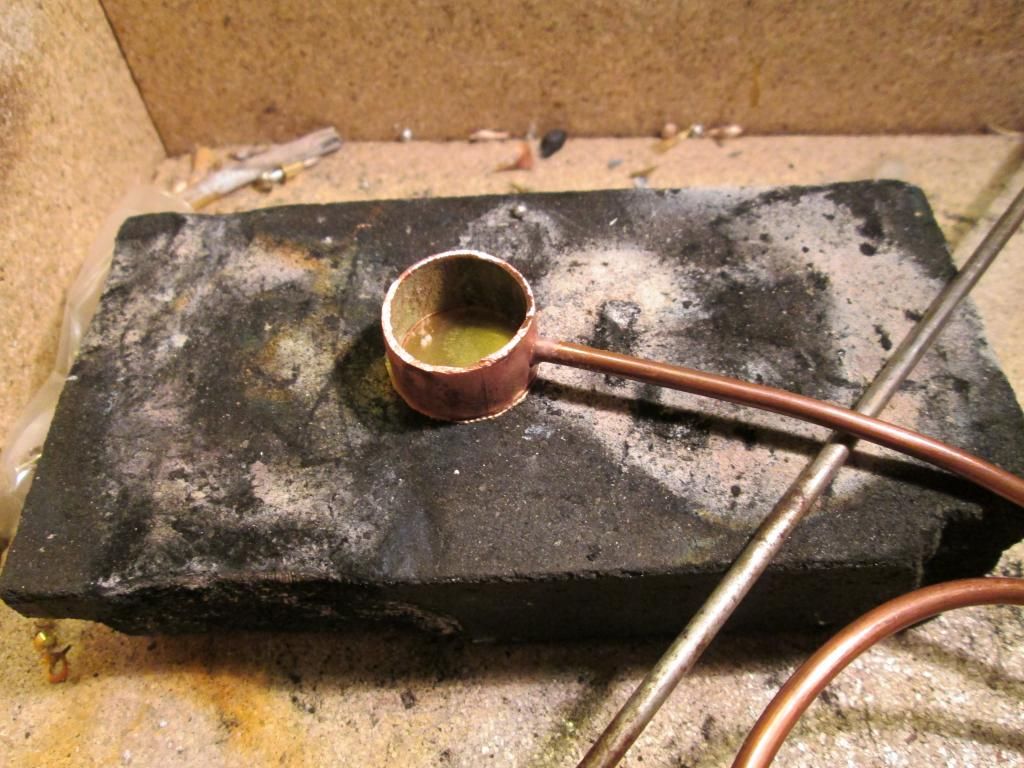
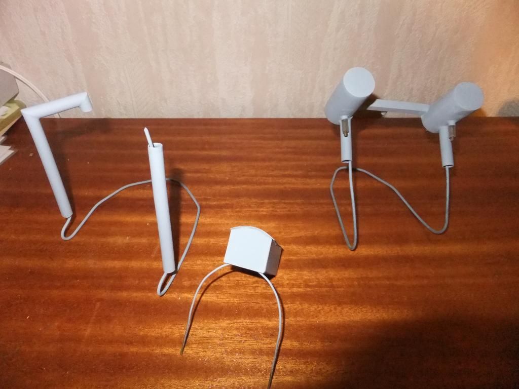
This decision holds up me finishing the condenser tanks. See below on what I have cobbled together so far.
My 'saddle' condenser tanks. The copper pipe was a bit of scrap found in the garden.
Roughly cut to size with the link between.
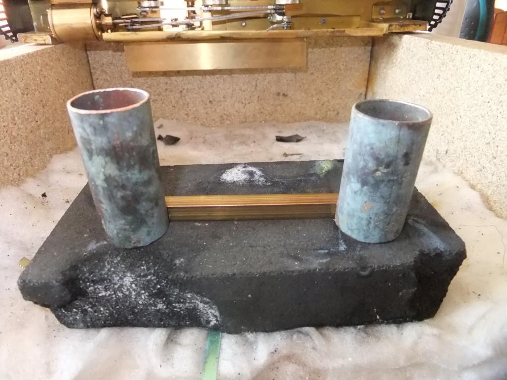
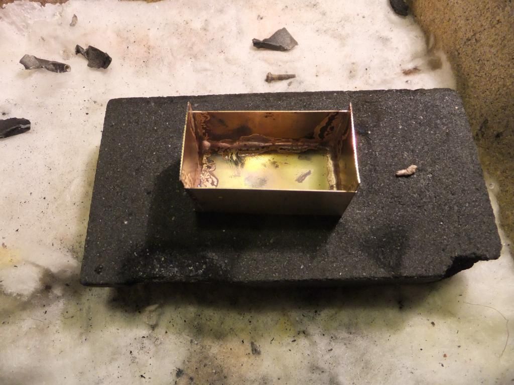
Soldered, filed and sanded to a respectable finish. I have not soldered the opposite ends on until I know where I am going to exit the steam.
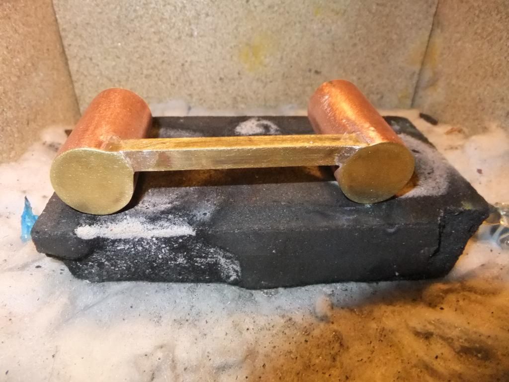
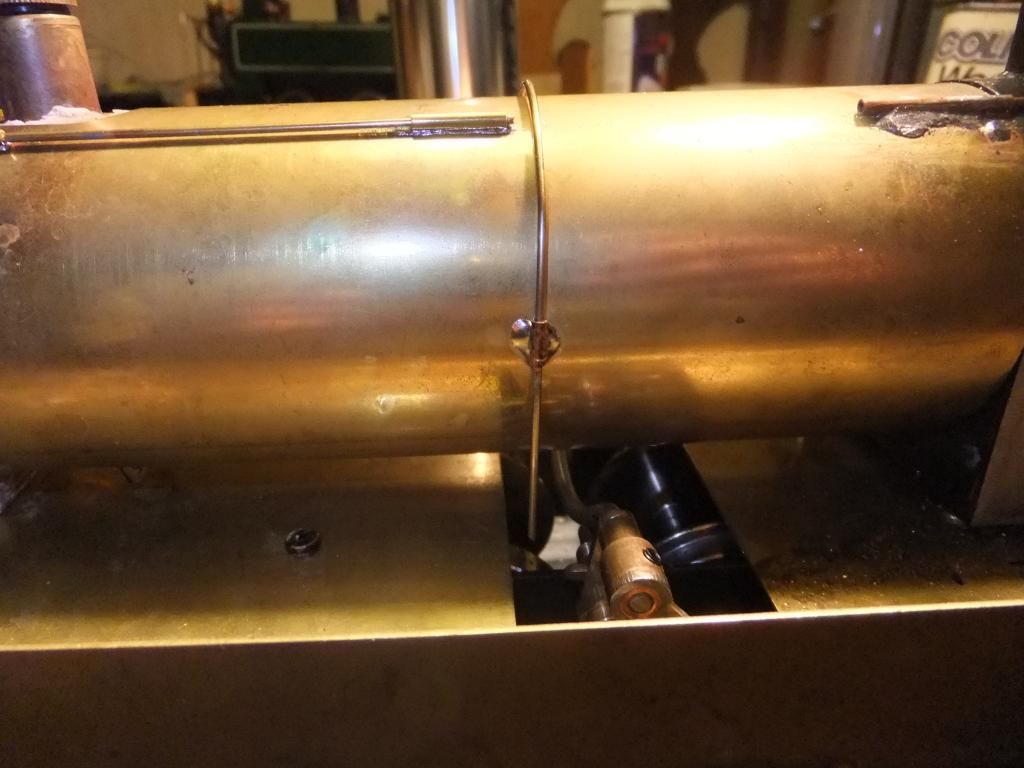
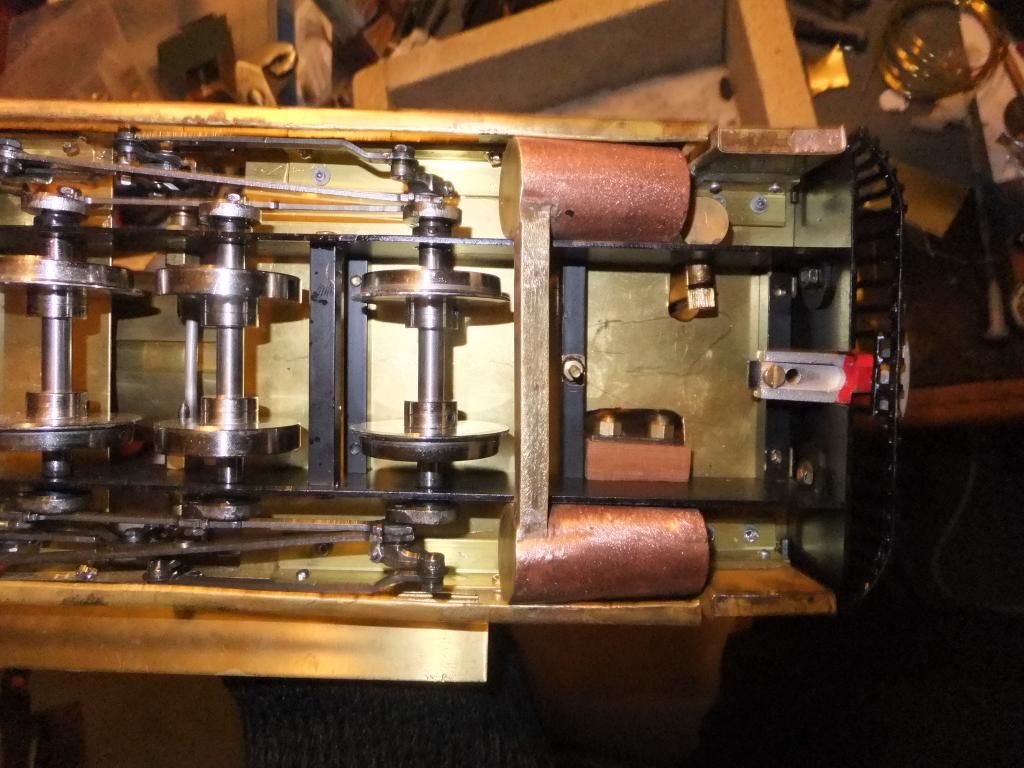
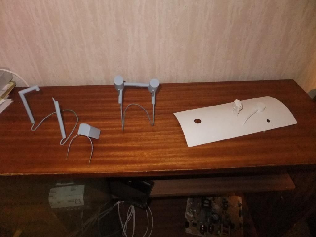
Sat in location under the side skirts. Frames not channelled to accept properly yet.
The idea is that the steam goes into one tank, through the link tube and into the other tank then out.
I am going to solder a small pipe to act as a drain on the link tube so the condensate exits rather than build up. I will probably pipe this between the wheels and up to the front of the loco so it looks like steam escaping underneath when stationary, a nice little realism. :roll: ;)
Sun Jun 30, 2013 10:54 pm
Wow Keith that chuff pot is amazing. I don't think my condenser tank is even in the same league! I don't know what made you think of it.
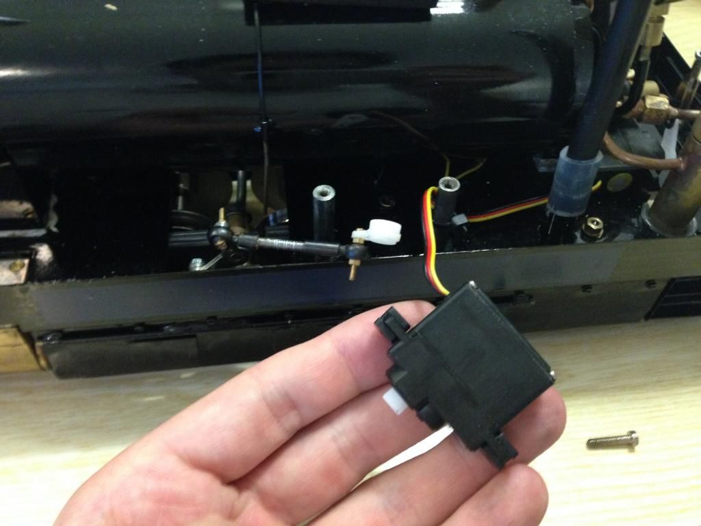
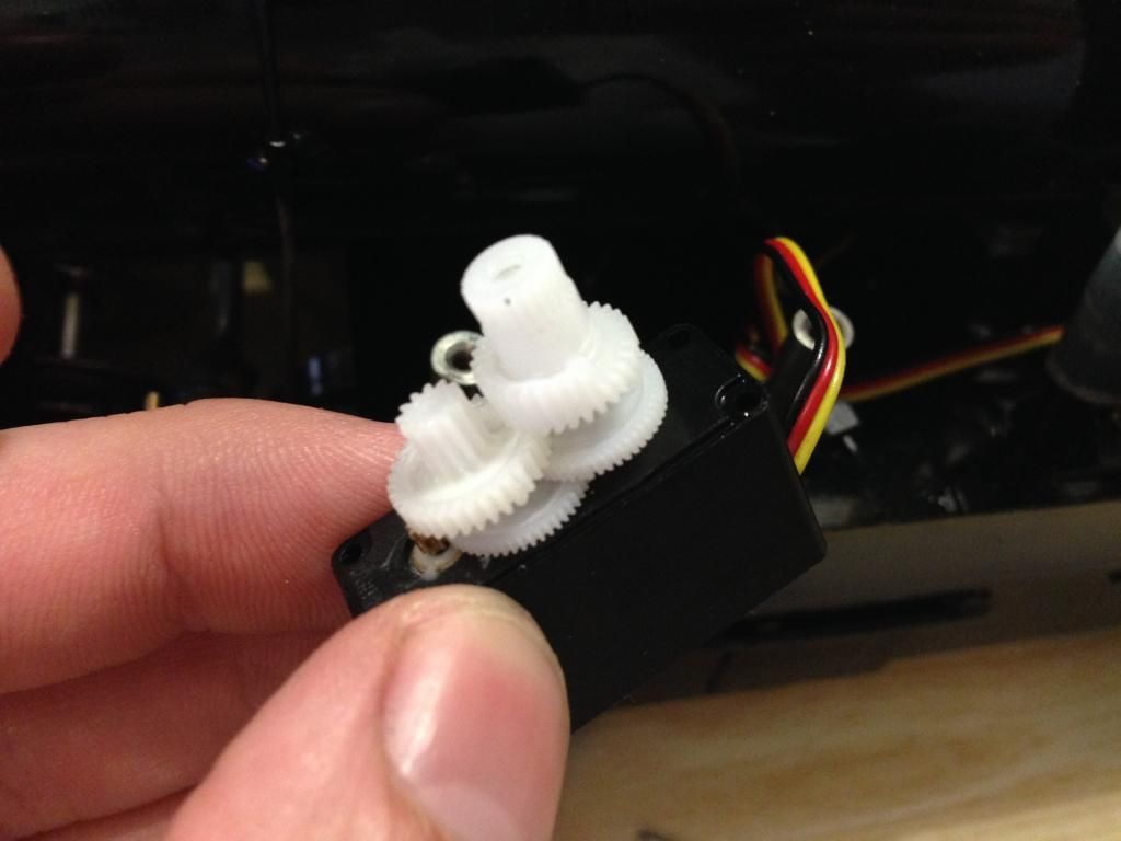
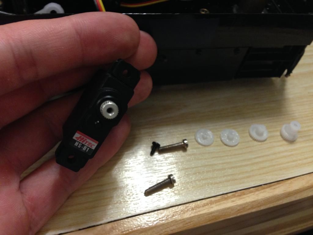
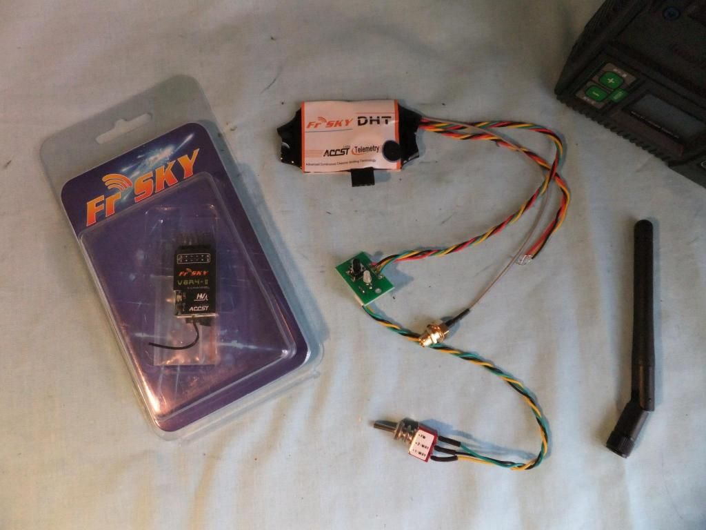
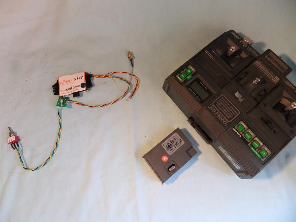
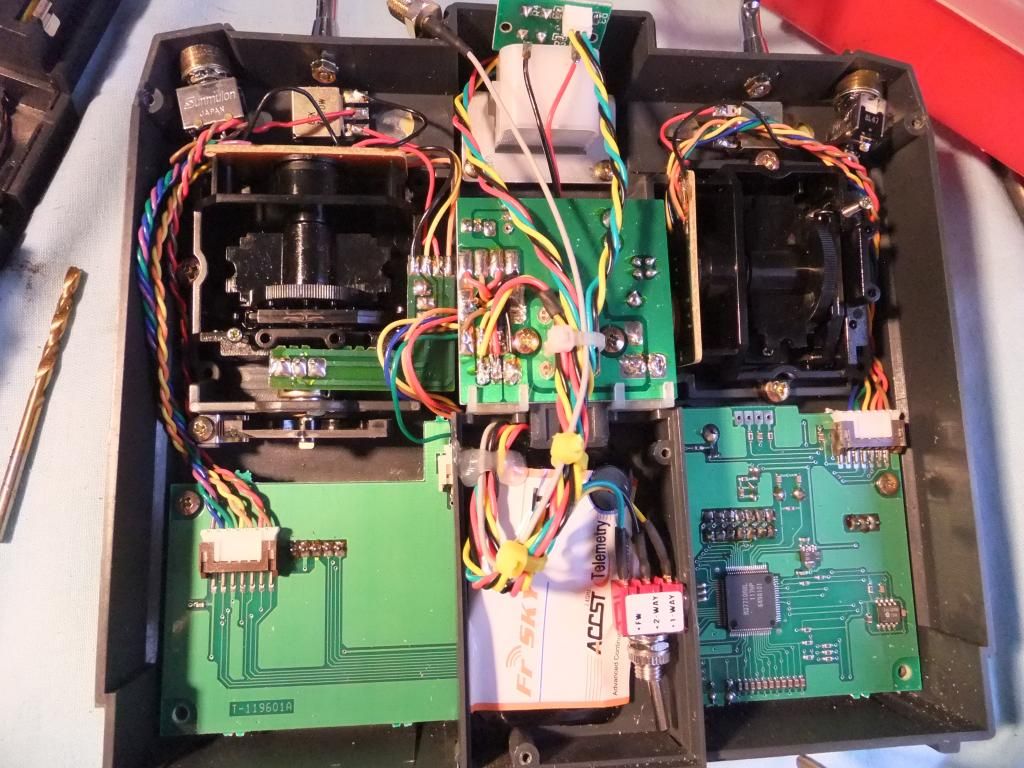
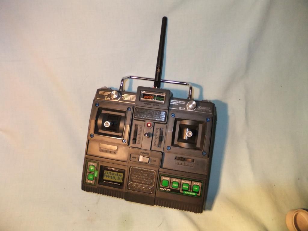
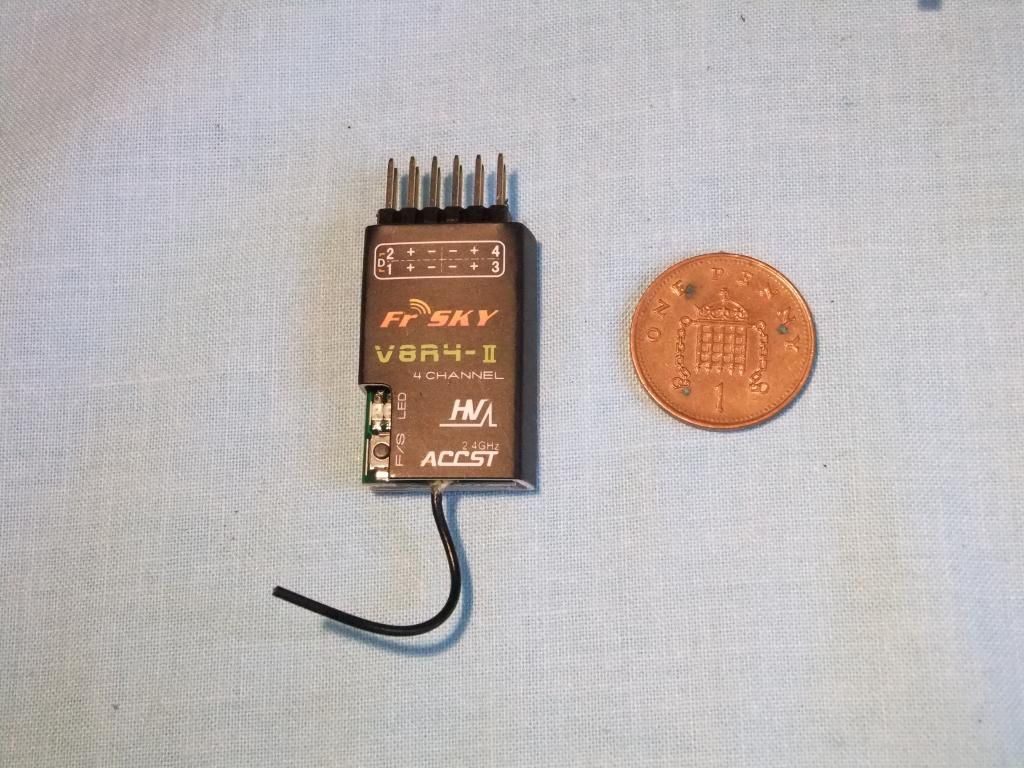
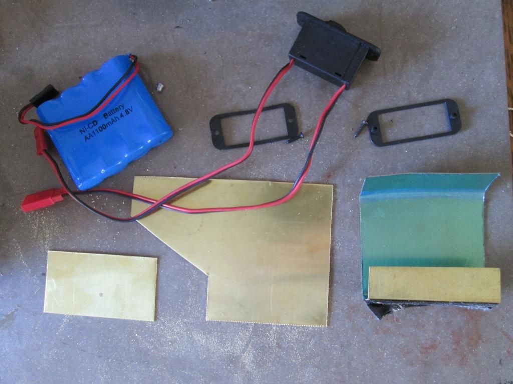
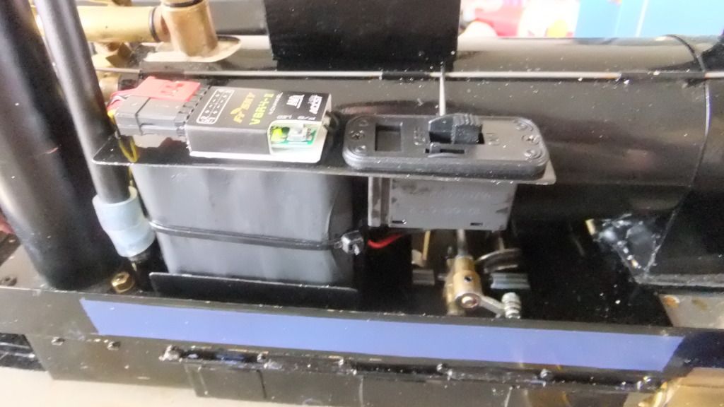
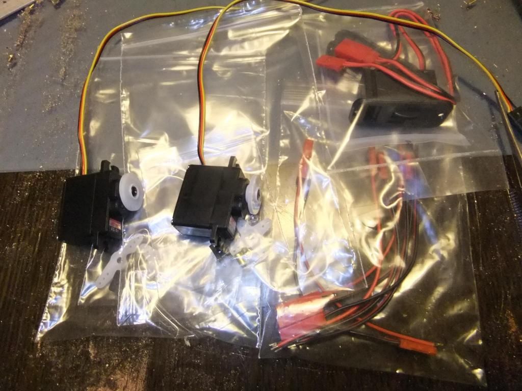
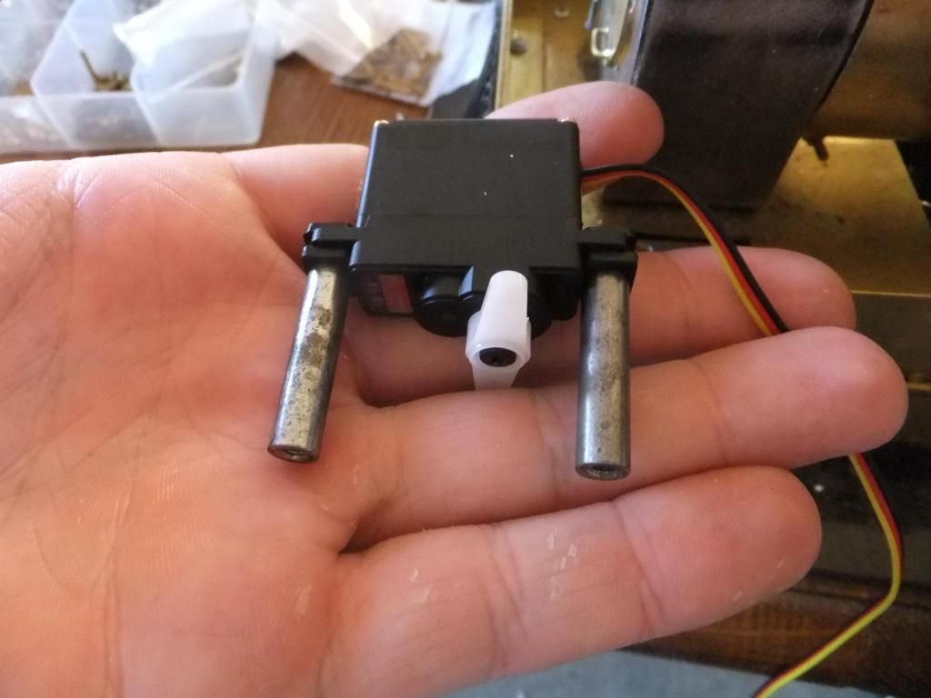
I did have some post on Saturday. Some of my parts have arrived! :D Both my servos and switch came with some leads for the battery packs. I ordered a receiver or two for a future tram project I have bubbling up in my head.
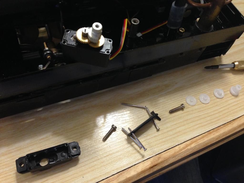
More about that on another thread.Here we go then, the new parts
In approximate location.
I'll get cracking with the R/C install as soon as possible.
Hopefully the postman will come again tomorrow with more presents!
Wed Jul 03, 2013 12:11 am
Hi Guys,
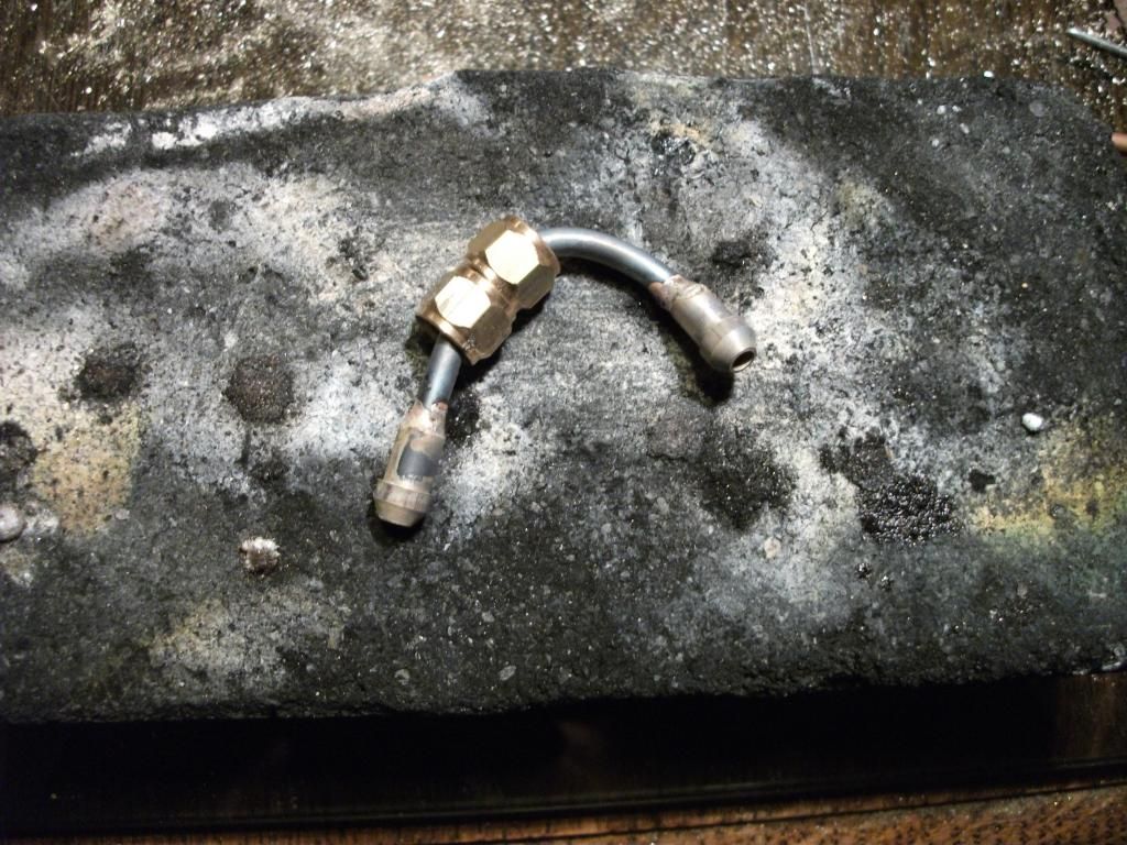
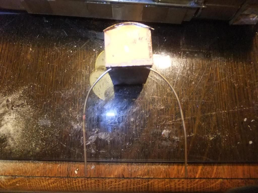
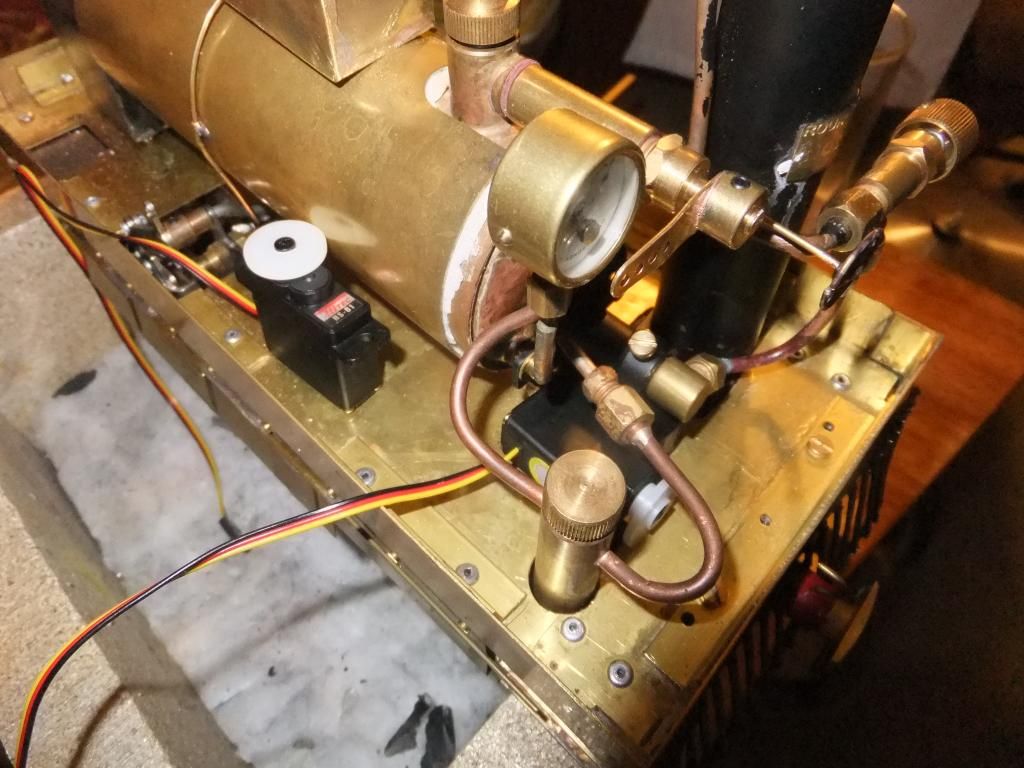
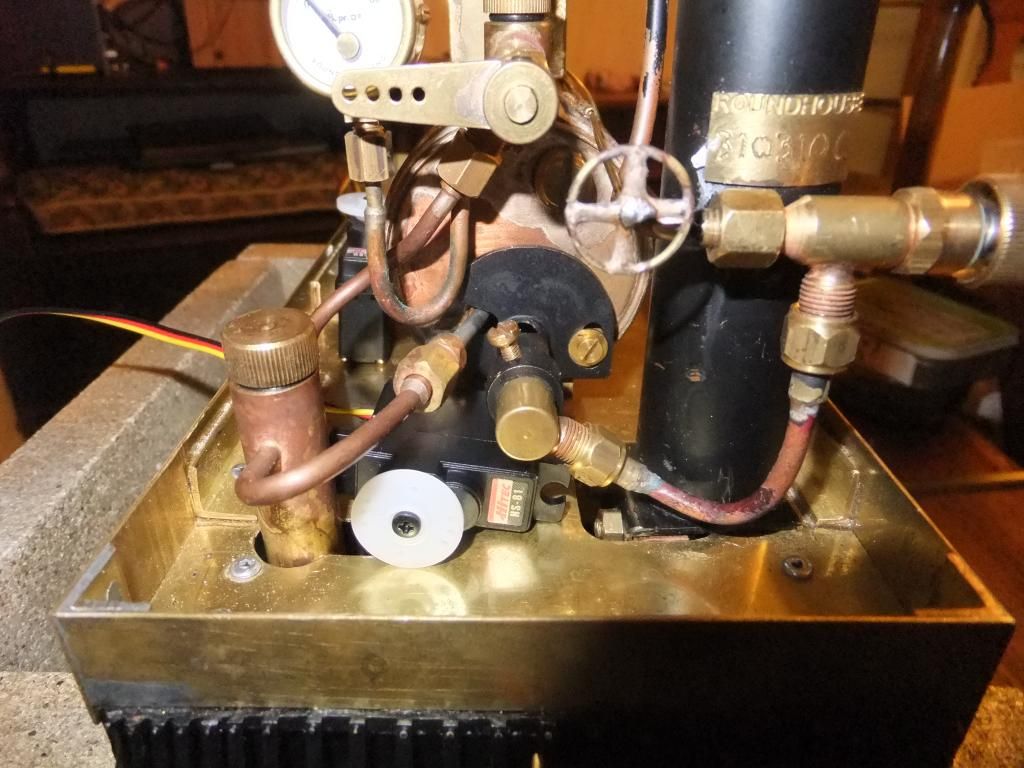
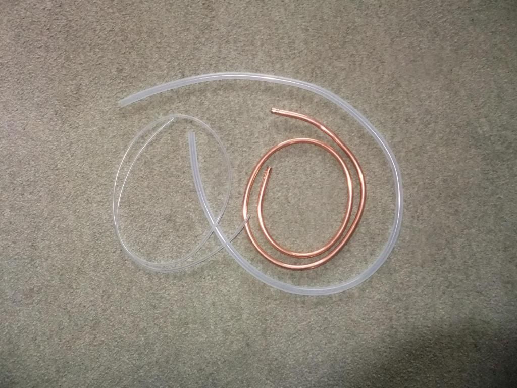
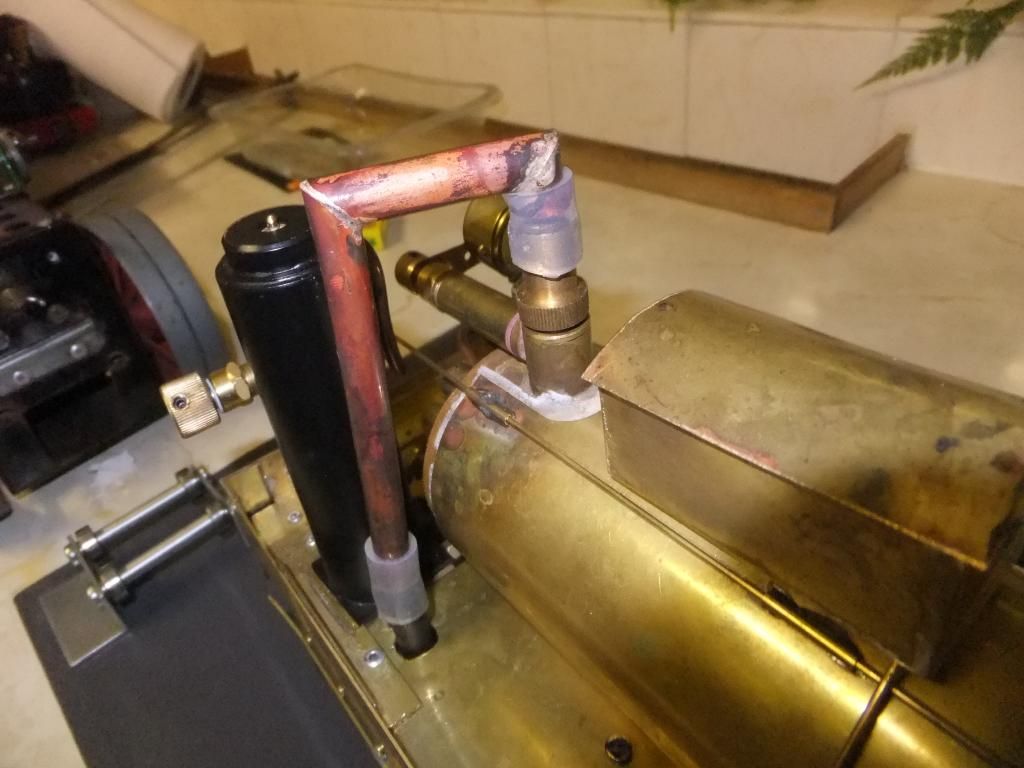
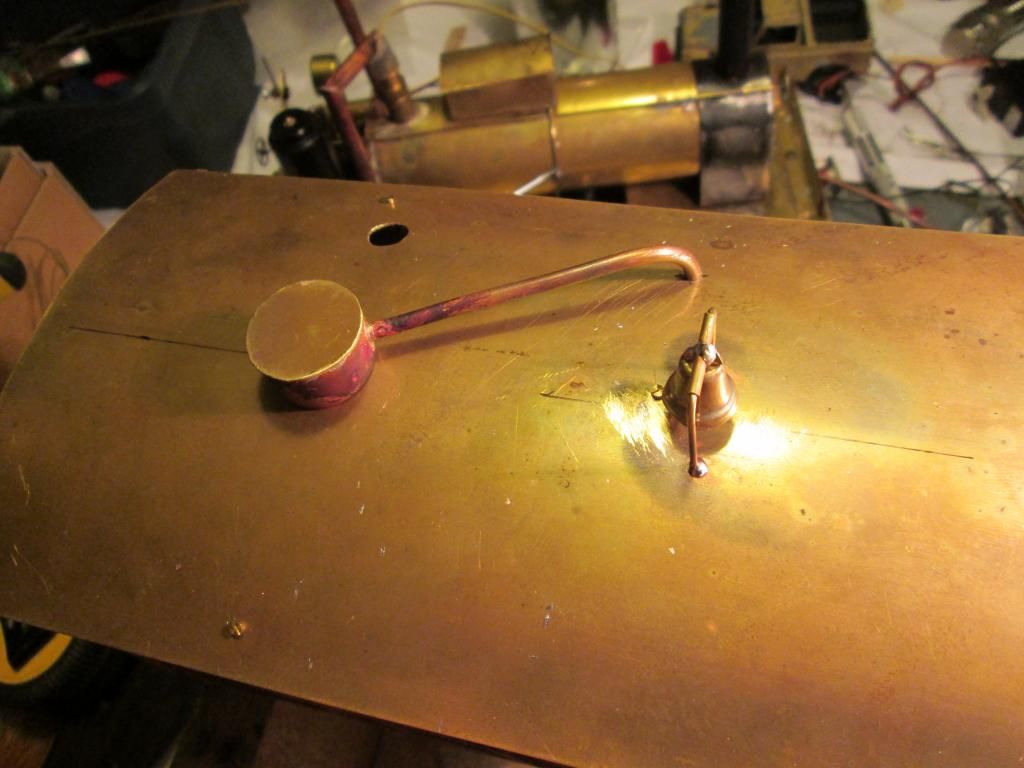
I had some more supplies today in the shape of some copper pipe and some silicone tubing. These are the last parts I needed to complete the condenser tanks and actually hook them up to the safety valve.
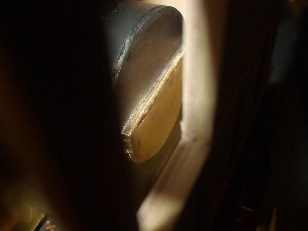
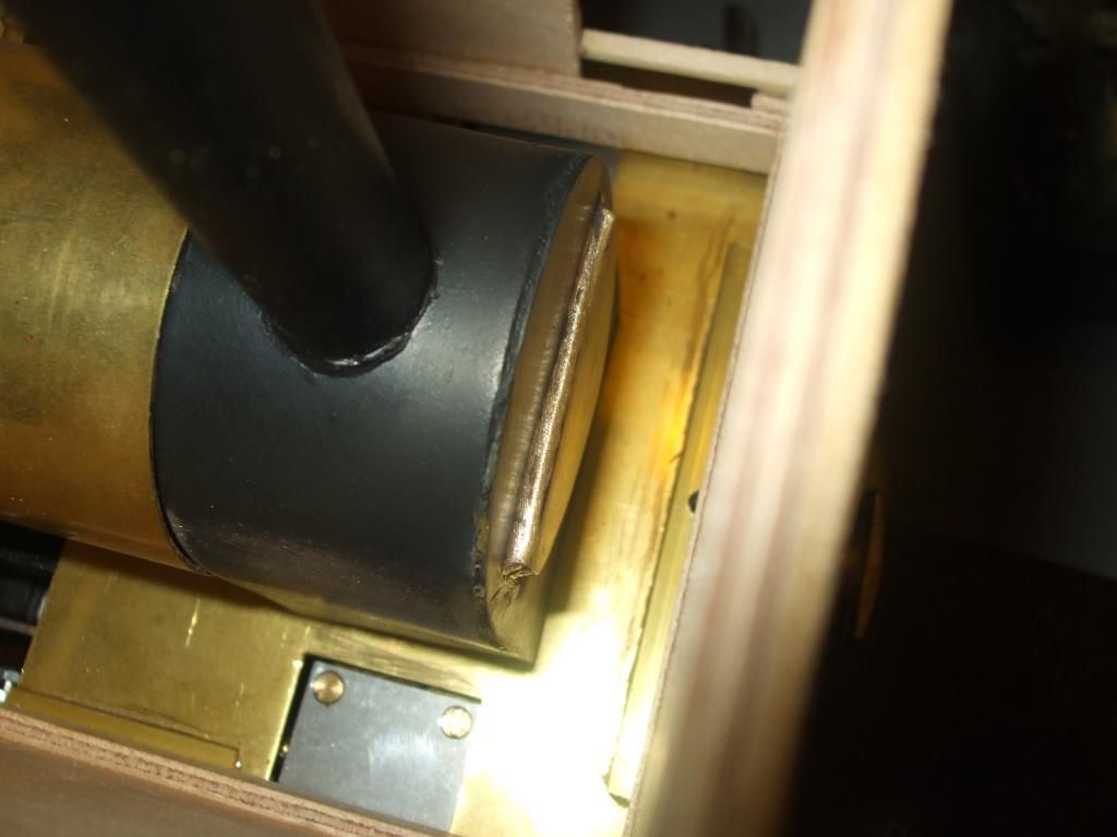
I began by starting to make the take off tubing from the top of that safety valve to go to the condenser tank. I tried to bend the piping, but I couldn't establish a tight enough bend to still fit under the cab, so I settled with 45 degree cuts and soldering.
And in location
The idea behind the short silicone tubing was to seal the sv against the exhaust and to pop off if any back pressure was to start.
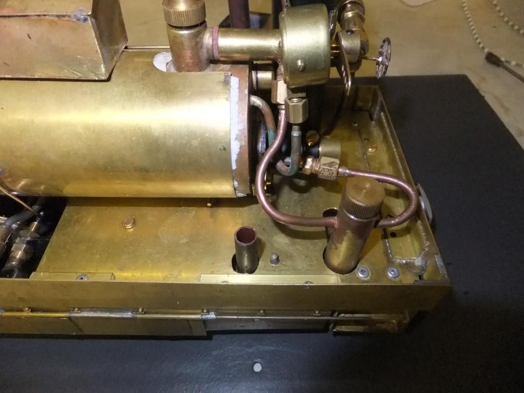
I finished off the tanks and make some more holes
I fitted some baffles inside the tanks so that the gas was forced to go the long way around the tubing and pipework
The idea is steam in the right vertical tube, around the baffle and out and into the saddle tube and entering the second tanks around the baffle and out the top left tube
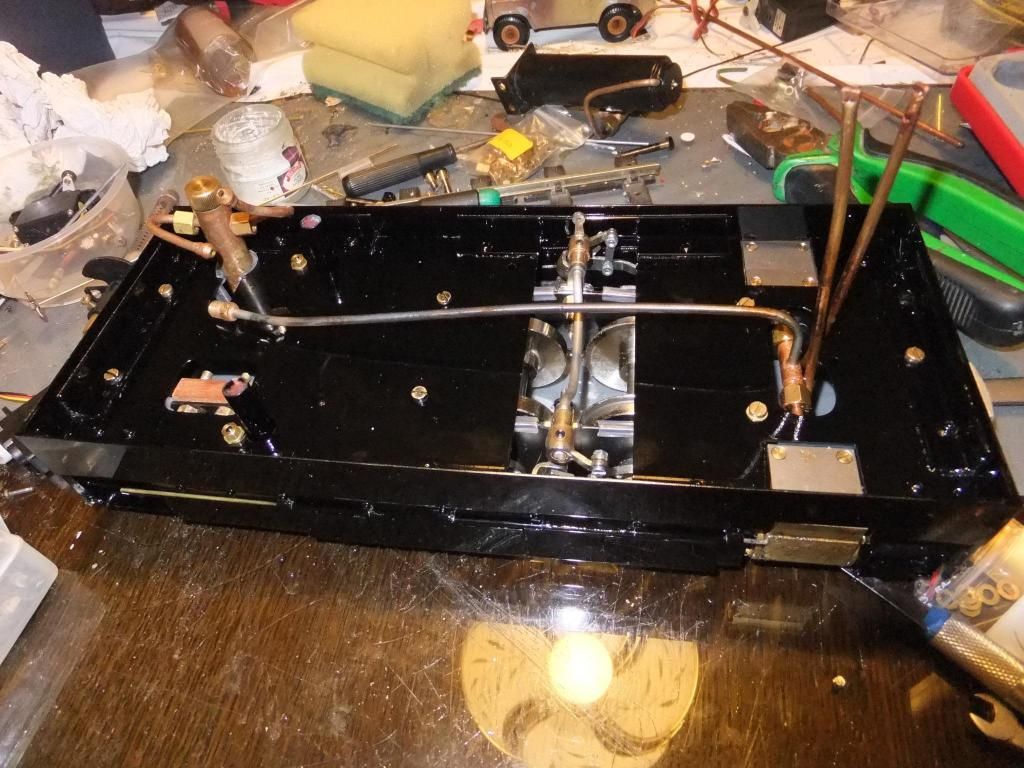
Tanks and pipework trial fitted.
This pipe will join up with the roof.
On test
A video of the condenser on test. The best bit is when I turn the gas off of the burner, notice the sound.
Pleased with it! :P
<object width="800" height="450"><param name="movie" value="//www.youtube.com/v/yoXmRK_PFdU?hl=en_GB& ... ram><param name="allowFullScreen" value="true"></param><param name="allowscriptaccess" value="always"></param><embed src="//www.youtube.com/v/yoXmRK_PFdU?hl=en_GB&version=3" type="application/x-shockwave-flash" width="800" height="450" allowscriptaccess="always" allowfullscreen="true"></embed></object>
Tue Jul 09, 2013 9:03 pm
A very small but important update.
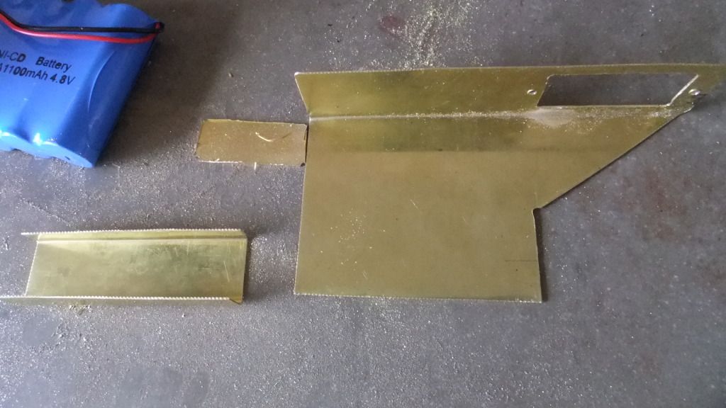
Ok, Now on with the R/C stuff. I have had some parts through, but not all. It is annoying because I need to work out it I have enough throw on the servo.
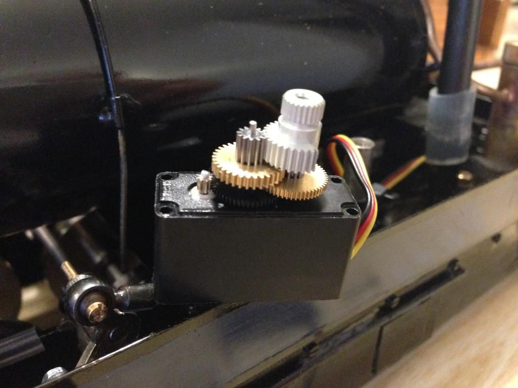
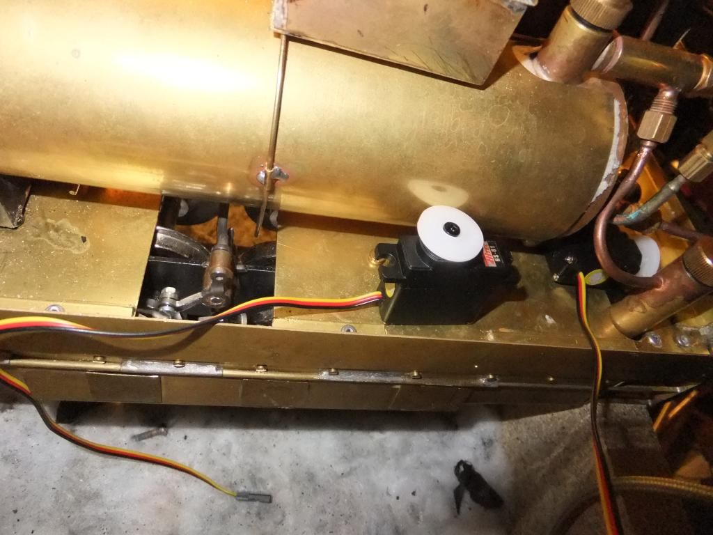
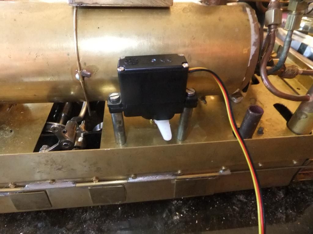
I was able to mount the direction servo onto the floor pan just now using a pair of old Mamod chassis frame spacers. Its amazing what you can put to use when you keep back lots of odd parts.
I just need to pop down to the model shop on the weekend to get a nice piece of threaded rod and some ball links or something similar. If possible some metal ones.
I now need to make the servo mounts for the floor based throttle servo. I suspect a pair of angled brass with a nut soldered to it will be the order for that one.
Mon Jul 15, 2013 11:20 pm
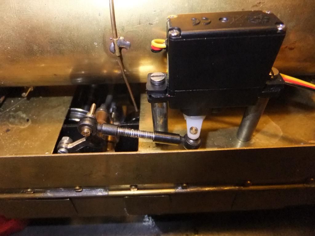
Well then, a productive update. I have made the linkages for the direction servo and also the throttle servo. The direction servo I am reasonably happy with, I do normally like to have all the links and arms perpendicular to one another in the park position normally, but space restrictions did not allow for such a setup. So I compromised... :?
The throttle servo is just taped to the cab floor for now. I had even less space for that one, plus its almost wedged under the gas burner. Not ideal, but it works all the same.
Direction servo. I was lucky enough to find some more metal ball links.
Throttle servo.
A short video clip showing it all working.
<object width="800" height="450"><param name="movie" value="//www.youtube.com/v/jpG_nbm4Tzs?version=3 ... ram><param name="allowFullScreen" value="true"></param><param name="allowscriptaccess" value="always"></param><embed src="//www.youtube.com/v/jpG_nbm4Tzs?version=3&hl=en_GB" type="application/x-shockwave-flash" width="800" height="450" allowscriptaccess="always" allowfullscreen="true"></embed></object>
Wed Jul 17, 2013 11:51 pm
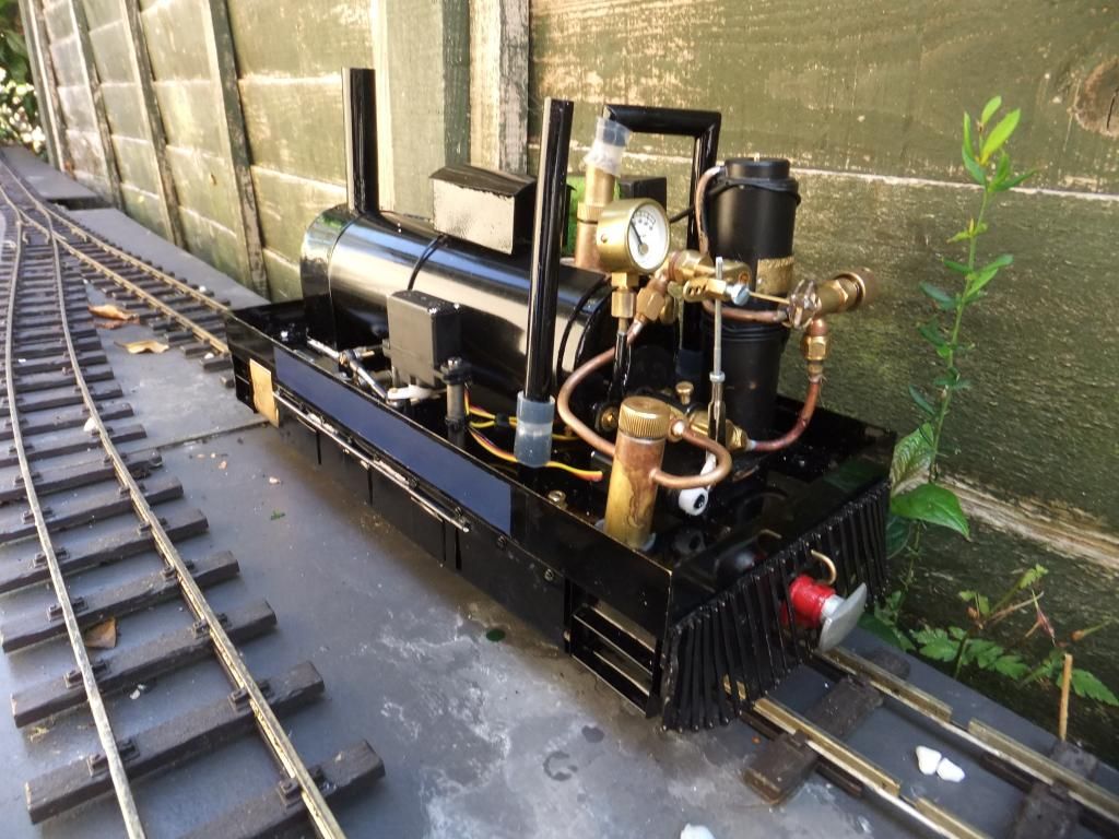
Well this evening I hit my long awaited target of making this tram 'mobile without intervention'. I have successfully installed R/C equipment and made it work.
I'll let the images do the talking.
Some 'upskirt' views
With cab on
Dwarfing a IP Engineering 'Ezee Rapier loco'
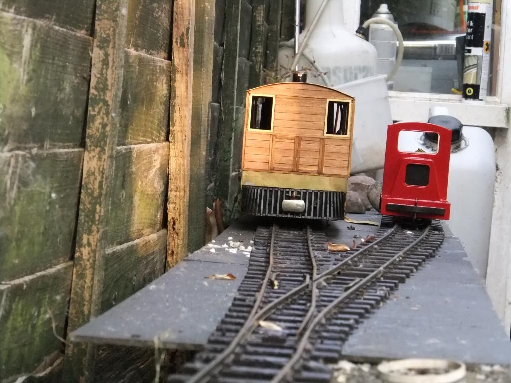
And finally a video. It does have some finishing details of the condenser included too.
<iframe width="853" height="480" src="//www.youtube.com/embed/64w5D19EvJM?rel=0" frameborder="0" allowfullscreen></iframe>
<object width="800" height="450"><param name="movie" value="//www.youtube.com/v/64w5D19EvJM?version=3 ... ram><param name="allowFullScreen" value="true"></param><param name="allowscriptaccess" value="always"></param><embed src="//www.youtube.com/v/64w5D19EvJM?version=3&hl=en_GB" type="application/x-shockwave-flash" width="800" height="450" allowscriptaccess="always" allowfullscreen="true"></embed></object>
Fri Jul 19, 2013 11:19 pm
Thanks for your kind words chaps, I really think I could do this alot better if I were to build again. Sometimes it feels so disjointed when having to dis and re assemble some of the time. I wonder, why didn't I think about this a little more?
Timvrip, I'm sorry to hear of your loss. It's never easy letting a good loco go...
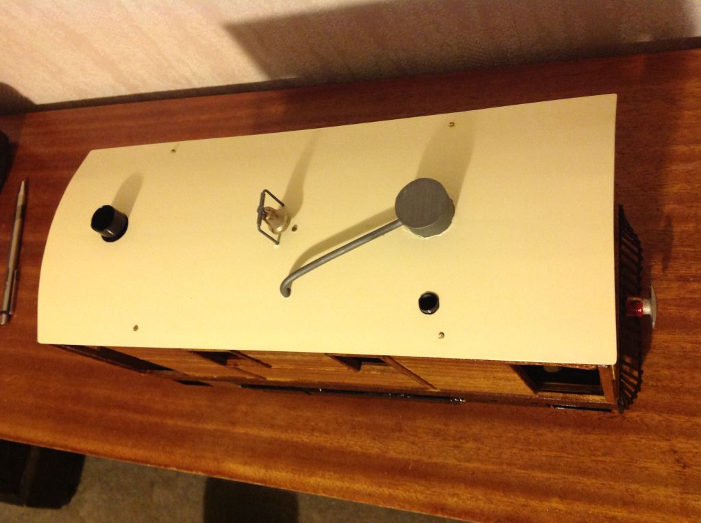
I have an update for you. I decided to concentrate on the cab roof a bit this evening.
Remember the little bell I was kindly donated previously? Well I now have it in situ.
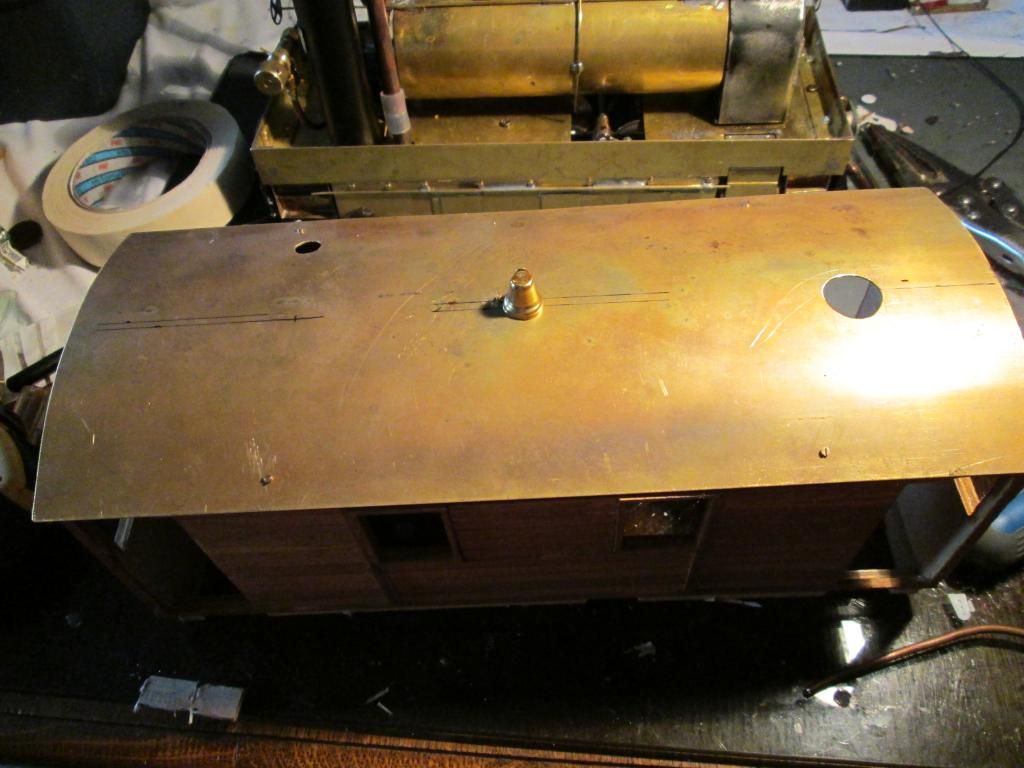
I soldered a piece of brass tube on it to keep it able to swing and to locate it in the middle of the carrier. The brass wire is the carrier with its first bend in place.
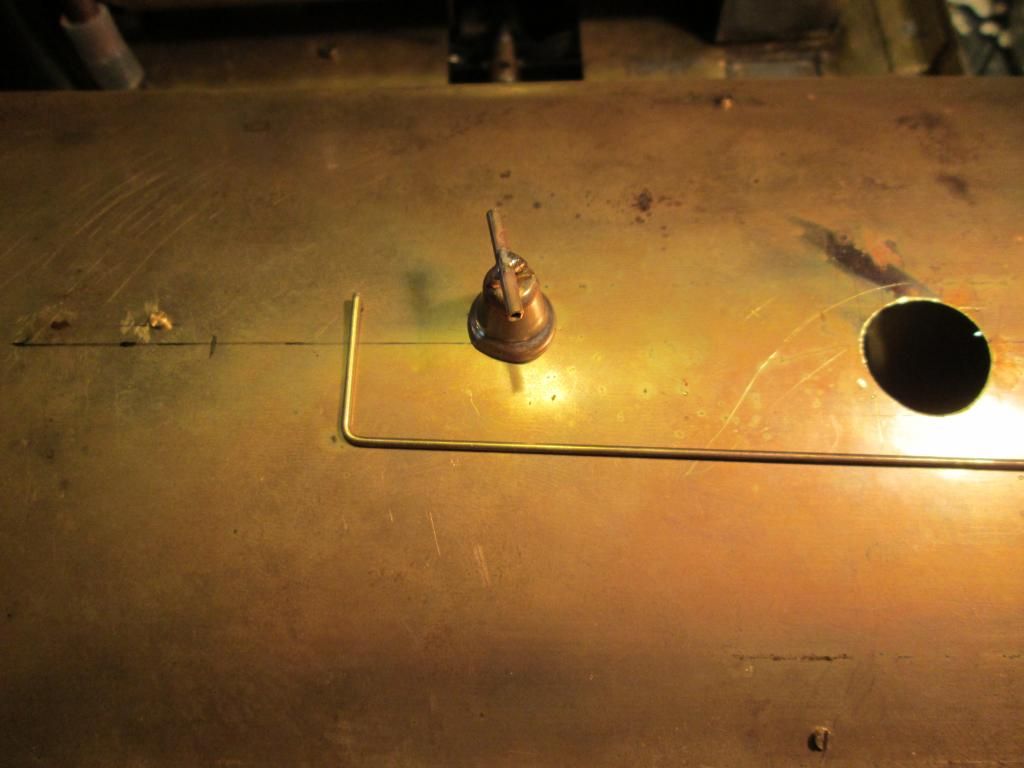
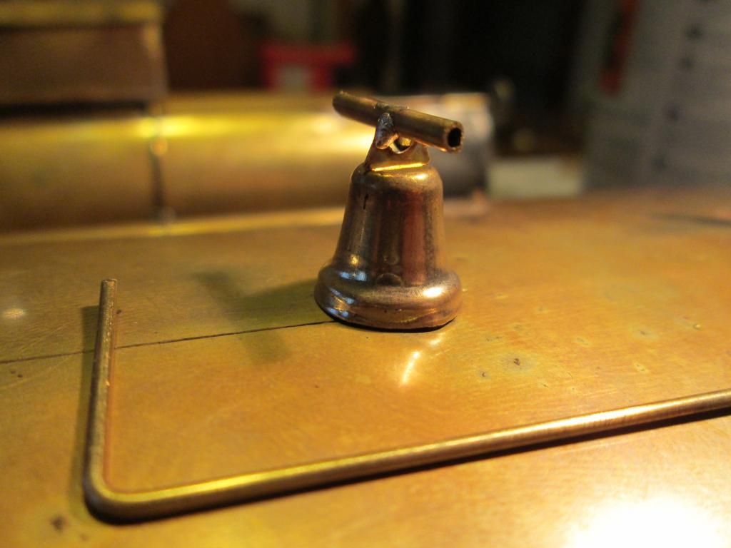
Here is the bell on its carrier
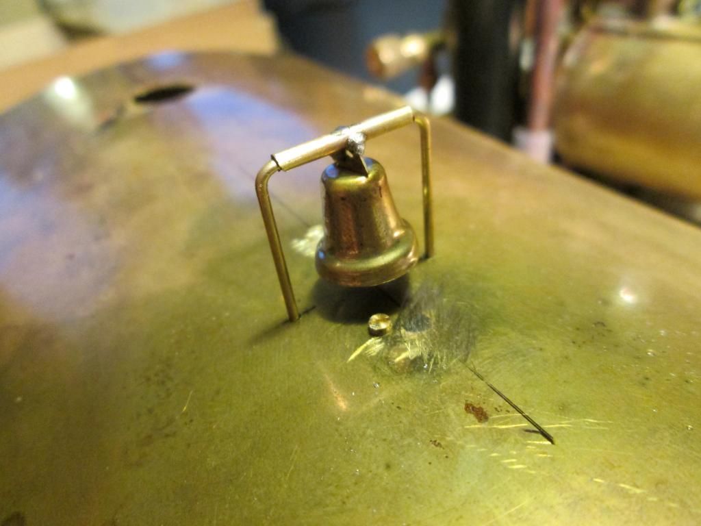
Here is the bell and carrier in place on the roof.
Next up is the safety valve cover. I had intended to make this functional, but this proved too difficult with having the flexibility of removing the cab roof.
This is a small piece of copper tube left over from the condenser tanks.
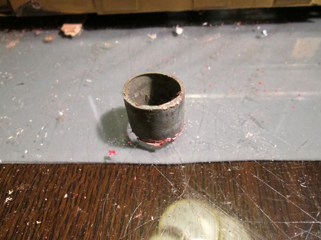
Cut down and a hole drilled.
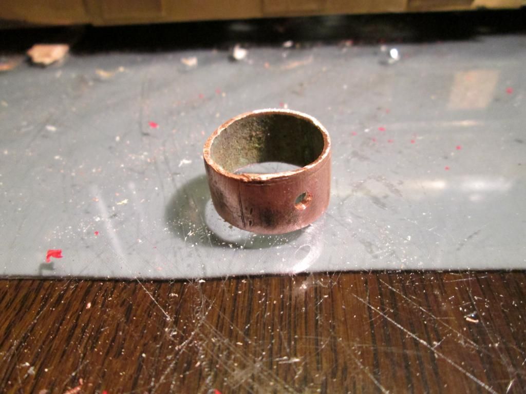
Copper pipe in place and a little lid for the safety valve cover.
Silver soldered, bent and cut to size.
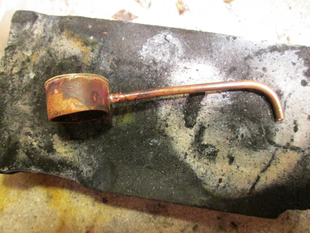
And in place on the roof.
So now I think I am at a point whereby I can finally get on with disassembly and the big paint up. The last thing I need to do now is make the mounting brackets for the throttle servo, drill the holes and then paint! :happy:
Thu Jul 25, 2013 9:46 pm
I just seem to be getting one of those 'going backward' feelings today. I had a final run with the tram and it seems like the timing is way out. To be honest is sounds like (if it were a car) it has a mis-fire. Very strange....
Anyway, I decided to strip it down and sort the timing issue on compressed air, as it is easier to do with the body off. And whilst I'm in there, I cracked on with some painting of components. I dusted of the airbrush and acquired some materials from work and did some priming.
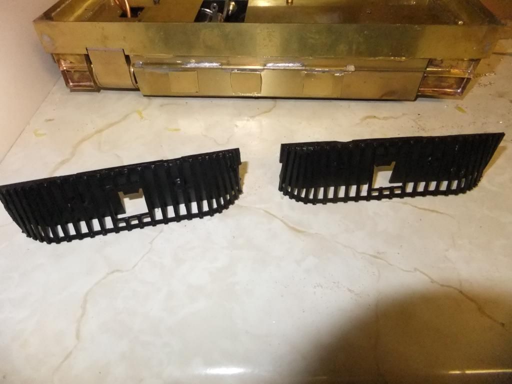
The loco as is now.
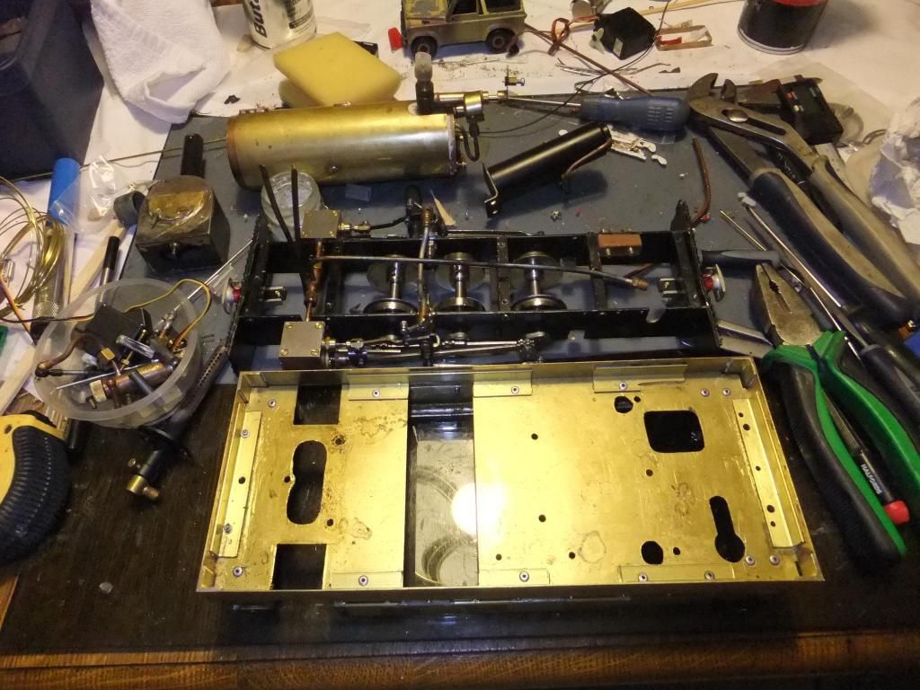
Some primed parts.
I need to do some trimming of the body in a couple of places so now is the time to do so. I'll then get cracking with the tub/floor pan section.
I must add, I am really looking forward to putting on the GER blue inlay onto the tub. I don't know why, just one part that appeals.
Sun Jul 28, 2013 10:14 pm
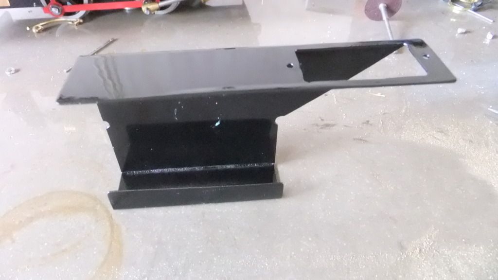
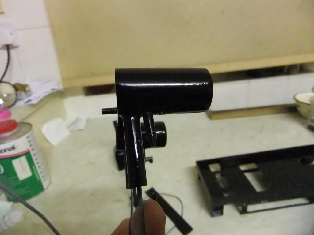
Well today was the big day and I managed to get some more priming done to the floor tub & smoke box.
Then I fired up the compressor and got cracking with some top coat.
All the previous primed parts were done apart from the roof.
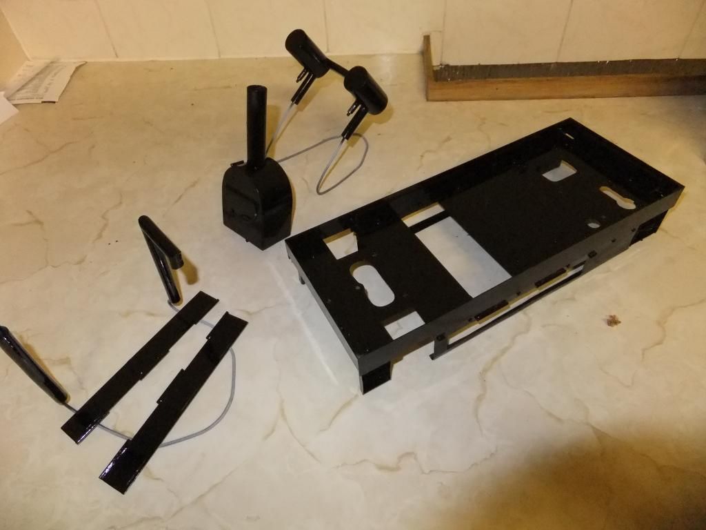
I did have problems with my oil and water trap half way through, so I left the parts in one coat of black for now. I will sand down the outer, showing faces and paint them again. I am a bit pissed off that this happened. Causing this effect on a couple of parts.
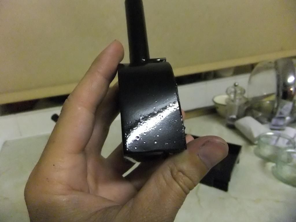
Well at least its not a car and just my tram I suppose...
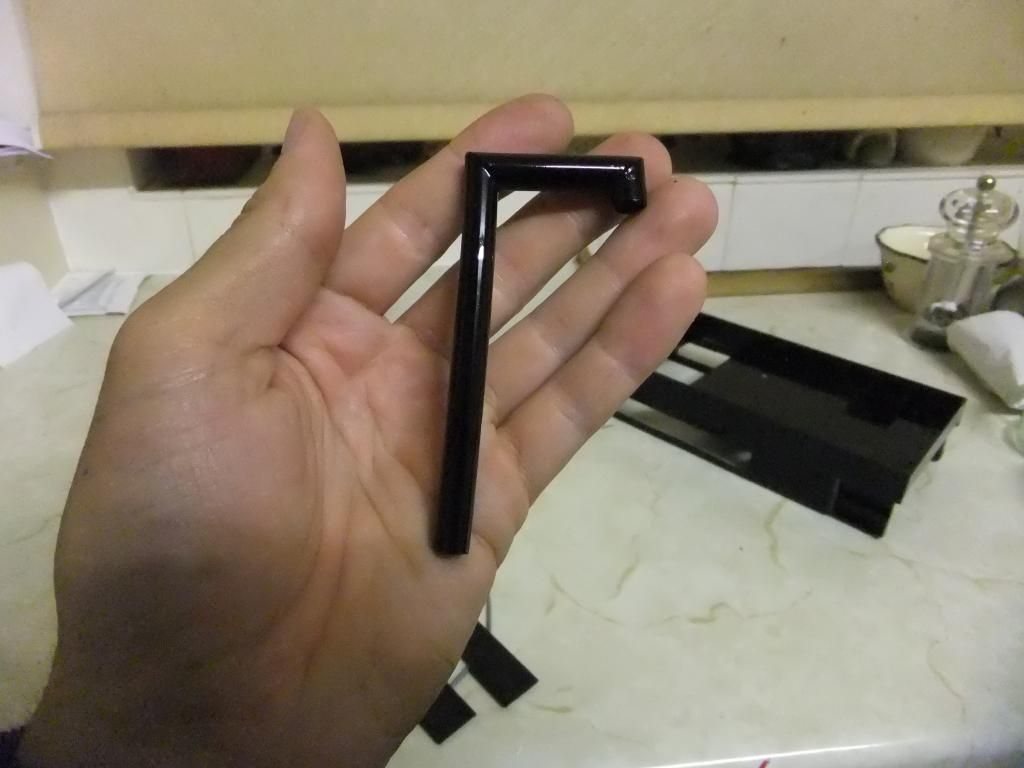
Anyway, shiny bits. 8)
Also I was pleased to discover that I had found a problem with the timing. So I had a little play with it and got it visually sorted. I just need to try on compressed air to confirm, phew! :D
Tue Jul 30, 2013 9:39 pm
Right, I started assembly tonight. First of all I decided on a way to rubber mount the floor tub from the chassis. Upon inaugural testing, it was found that there was a certain amount of 'rattle' when travelling over bumps, resulting in the flying tea tray affect. I fell upon this idea to try and prevent the 'rattle'.
I used some silicone tubing cut it to length then sliced open down one side and slid it over the chassis frame top. It holds itself in place adequately enough to fit the tub back on.
I also used the same method to snugly fit the lubricator in position.
Condenser tanks in position, with silicone tubing around the chassis.
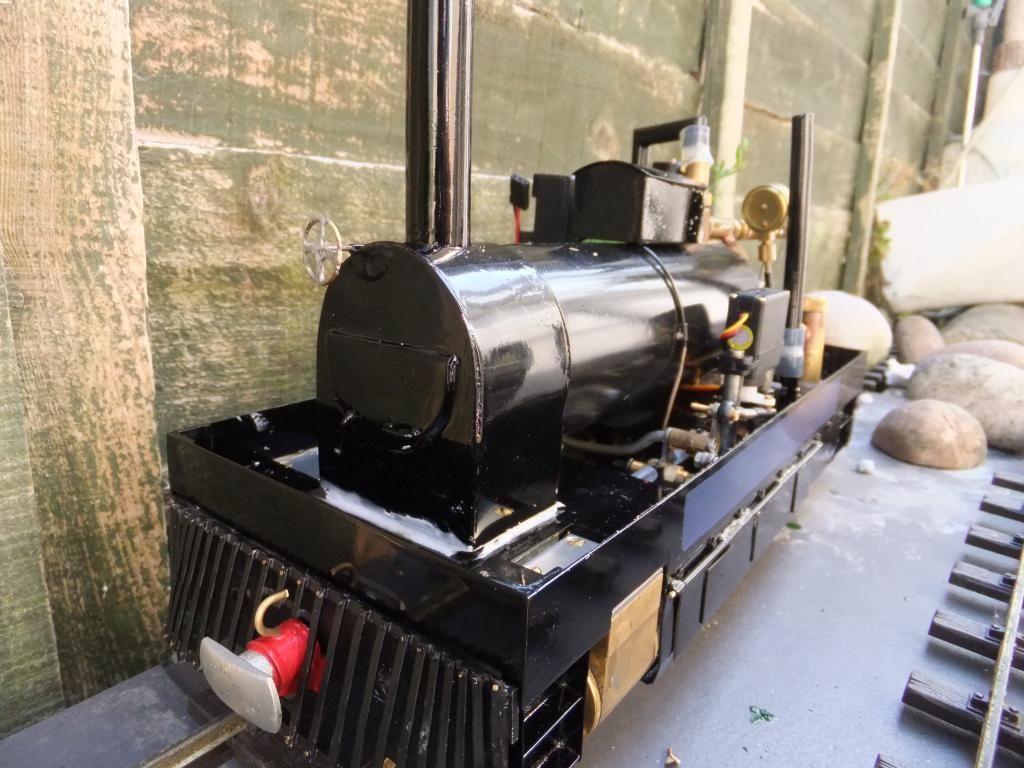
I wanted the cylinders to be a bit of a focal point, I was going to leave them to tarnish on their own. Does anyone think I should paint them?
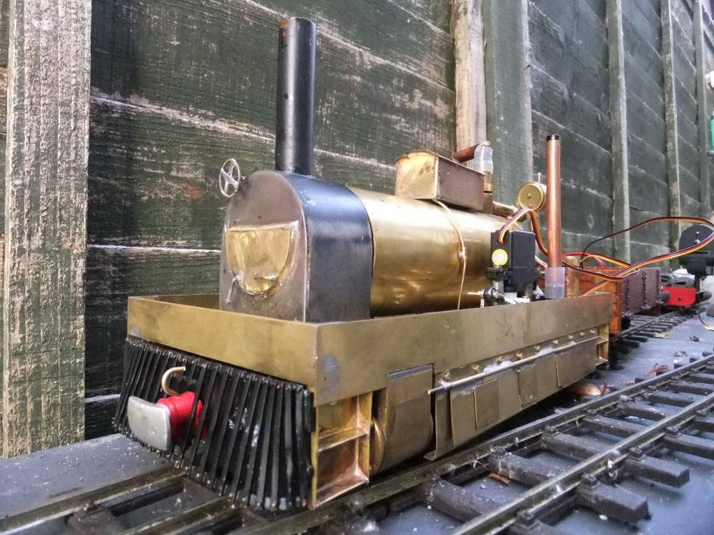
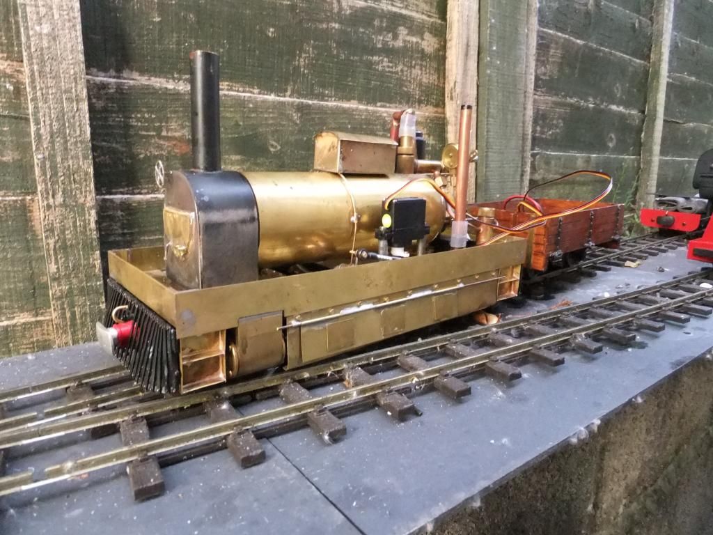
How she stands now.
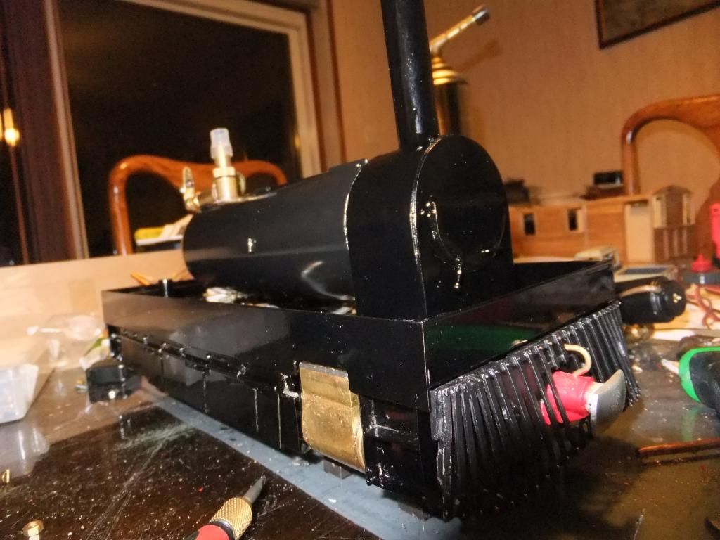
Go on, smile! :lol:
Aug 03, 2013 9:13 pm
A little update this evening.
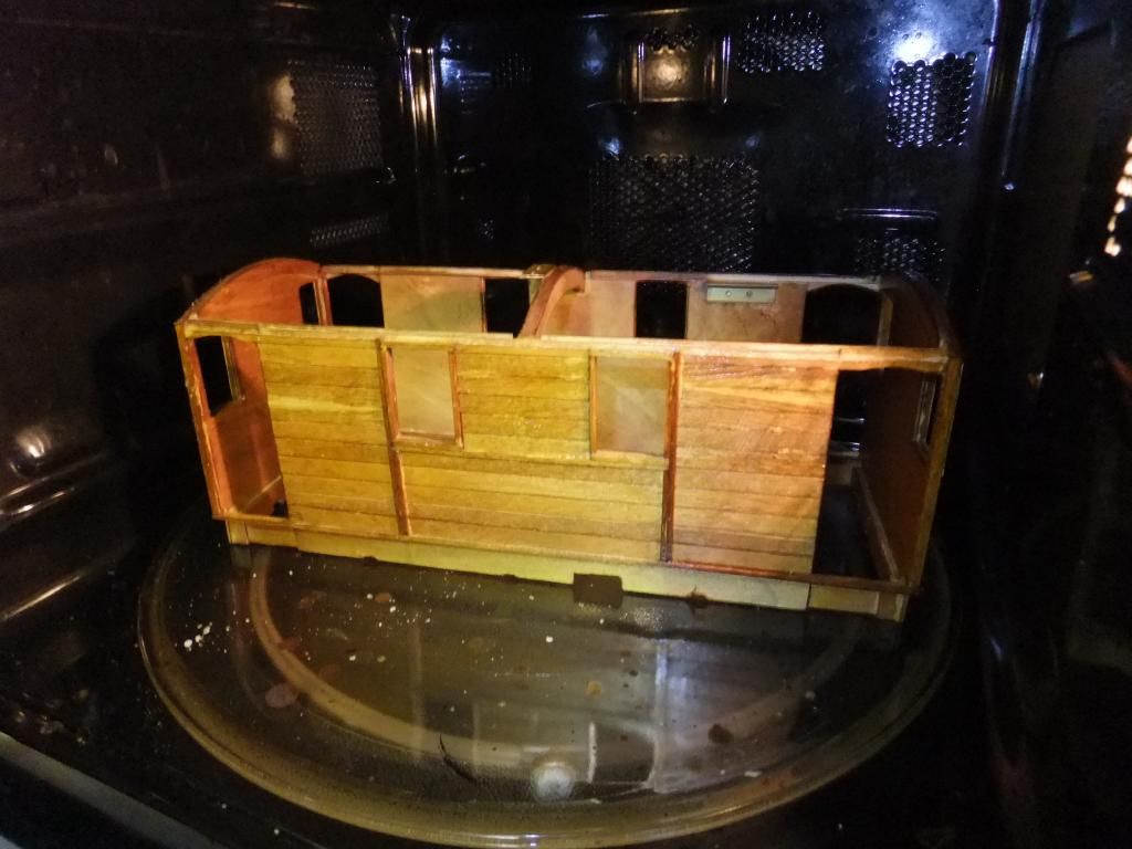
I did some wood finishing today. I cracked on with some coating of the body.
My Dad gave me this stuff to coat the wood in. He preceded to show me a piece of furniture that he had just finished and given to me with this coating on. It is rather nice. As it says on the bottle it is heat, impact, alcohol and solvent resistant. Sounds like everything a model steam engine needs. Time will tell if it is any good.
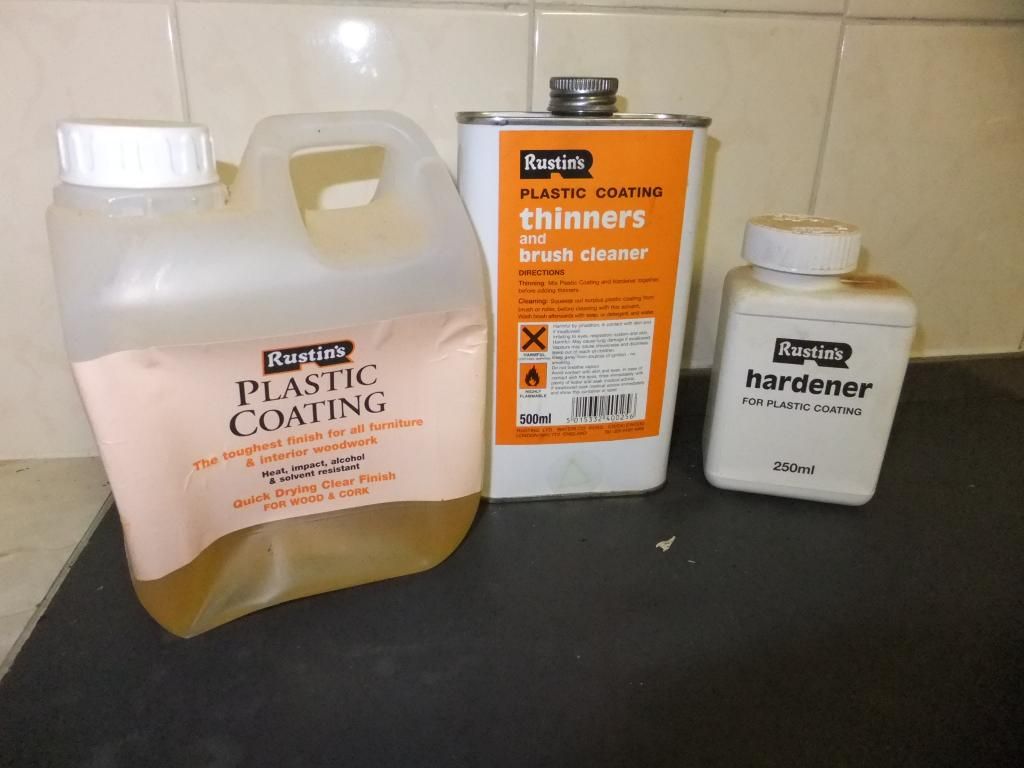
I was going to put it through my spray gun, but I figured I wanted a bit of an effect to texture the wood. I also didn't use any sanding sealer so the coating would soak in. What I didn't want after all was a ultra high gloss finish after all. Here is the difference, I like the colour that it has turned into. A well chosen stain, more by luck than judgement.
A quick 40 degree bake, and I applied another coat.
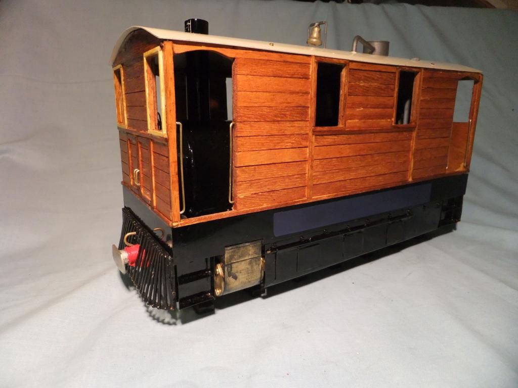
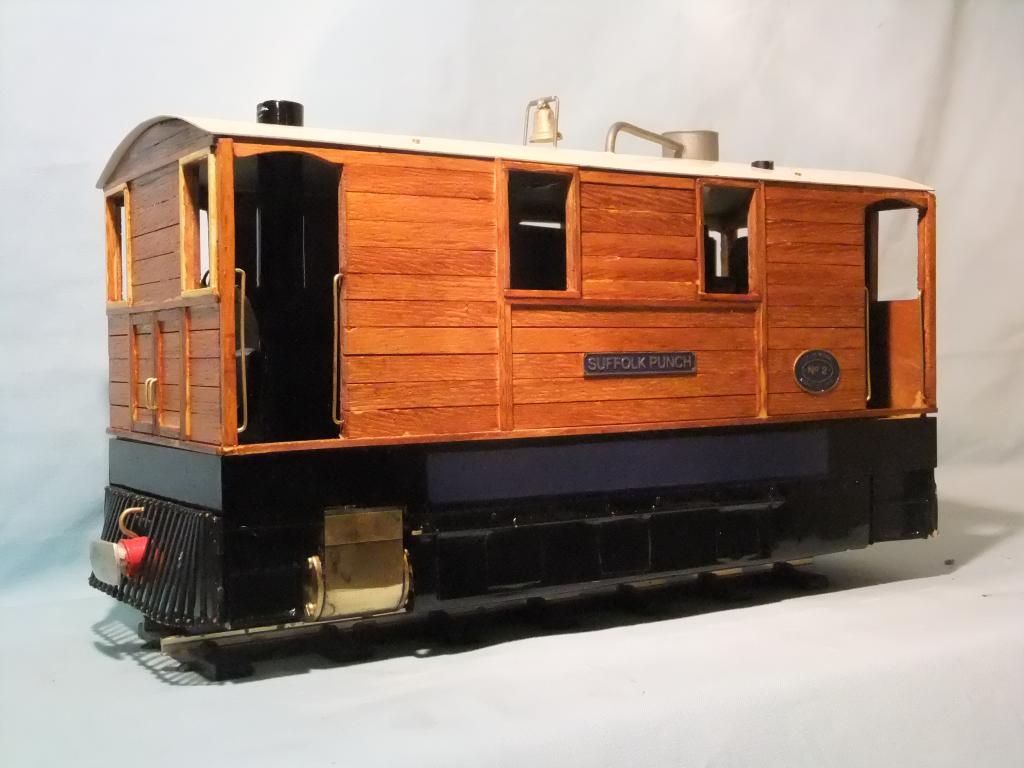
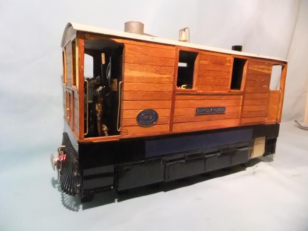
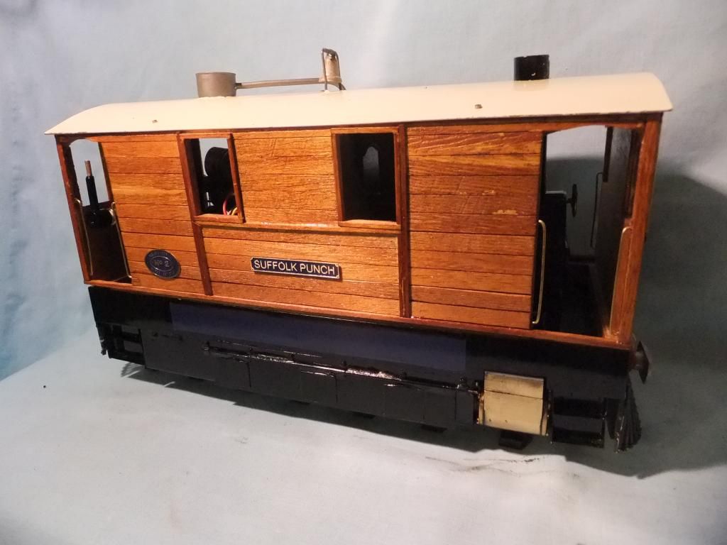
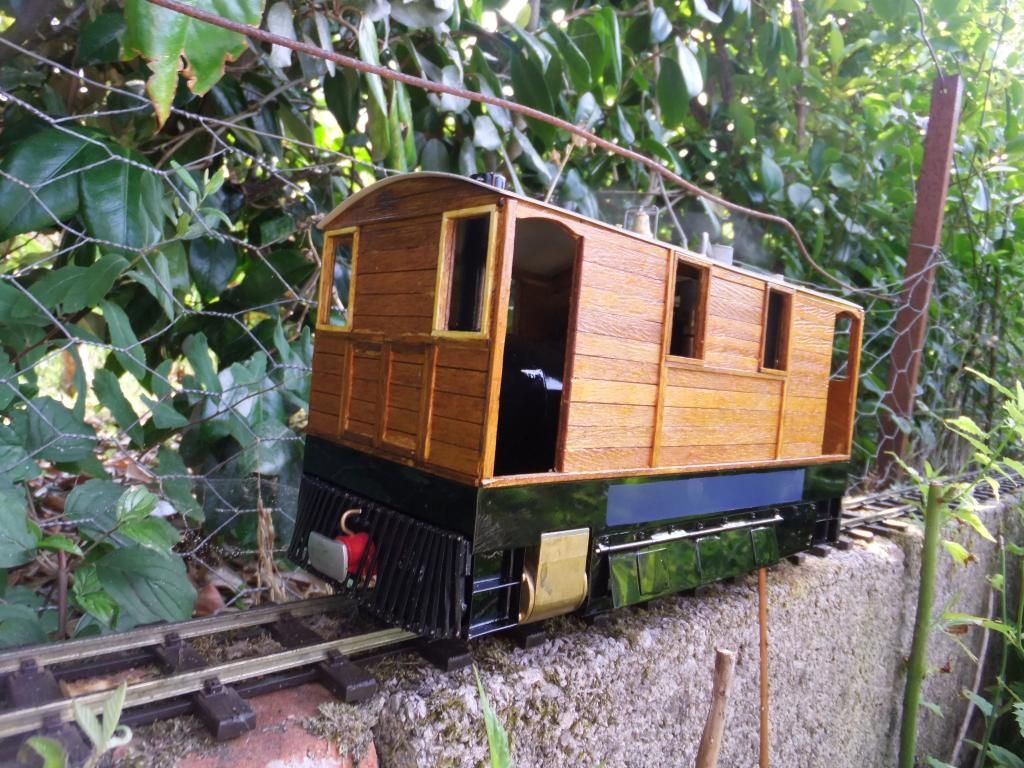
I can nearly say 'ex works pictures'. I did make a hash of the roof, so I am going to paint strip that and do it again. I need to detail the bell and false safety valve take off too, but you get the general idea.
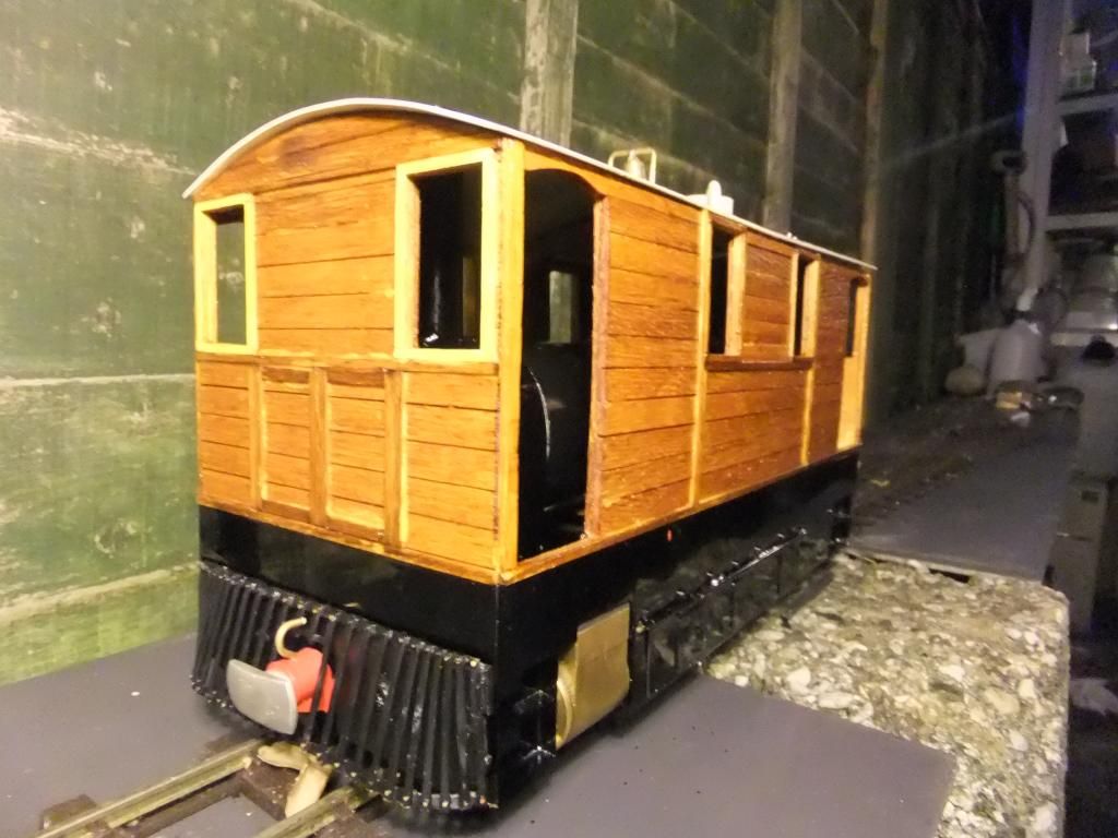
You get the impression of the satin sheen in this photo.
It is coming together nicely now.
Mon Aug 05, 2013 10:43 pm
Once again thanks for the kind words.
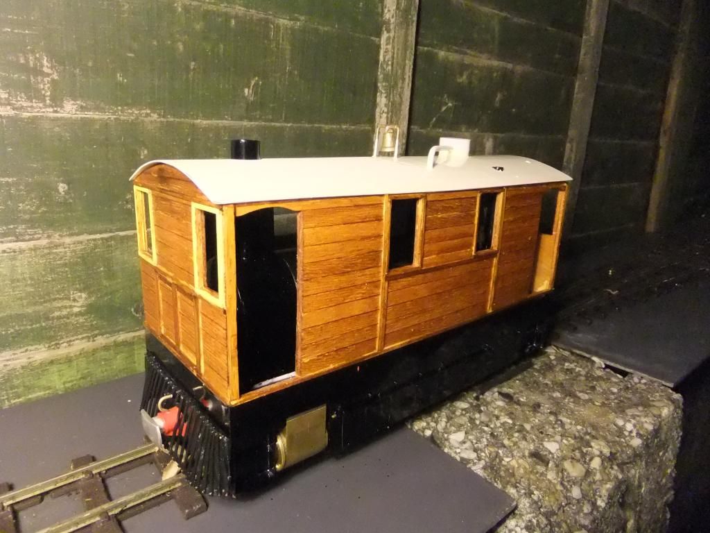
Not much of a productive update. I paint stripped the roof, re primered and re coloured, not quite perfect, but it will do for now. I just need to de nib the paint when it is hard enough and polish it.
I detailed the roof a bit.
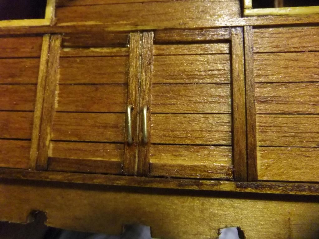
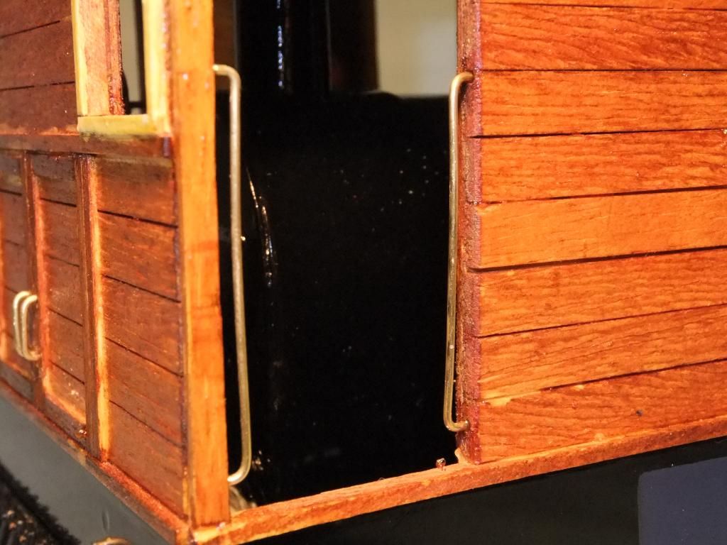
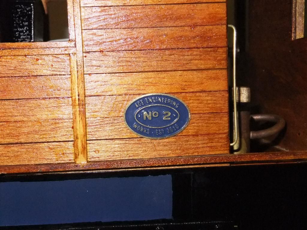
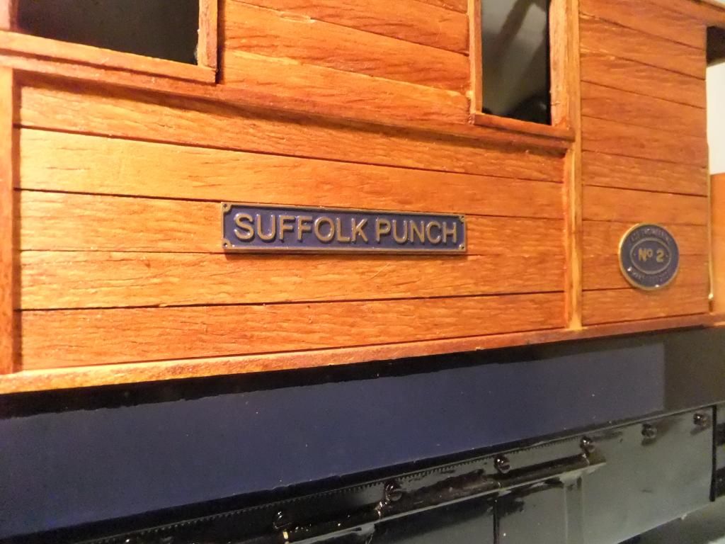
I just need to put the blue inlay on the side of the tub. I do want to make some cab handrails, mount a lamp on either end and possibly put the effect of a catch on the front and rear doors.
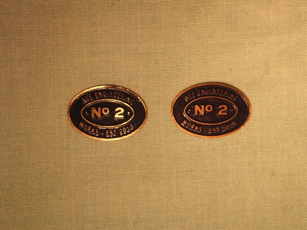
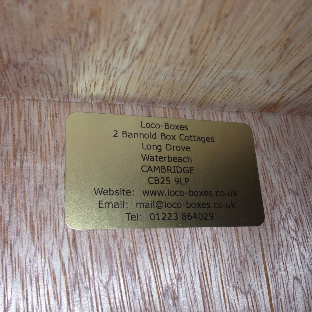
I have ordered some custom works plates for a few models, this one included, so they are coming up soon I hope.
Thu Aug 08, 2013 10:51 am
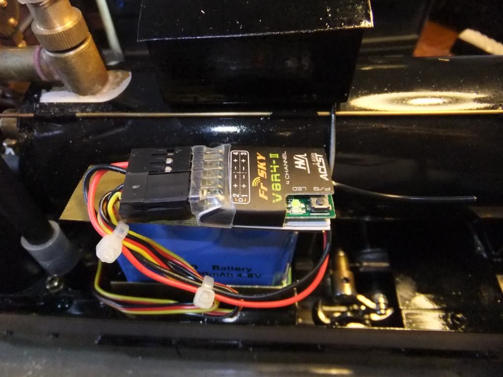
I have still not gotten my receiver for this tram yet, so I decided to borrow the one from my R/C car for the time being.
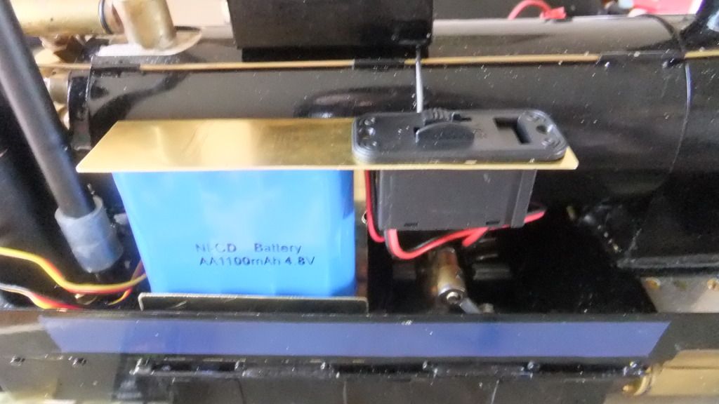
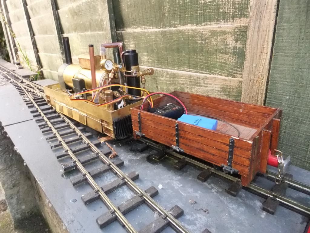
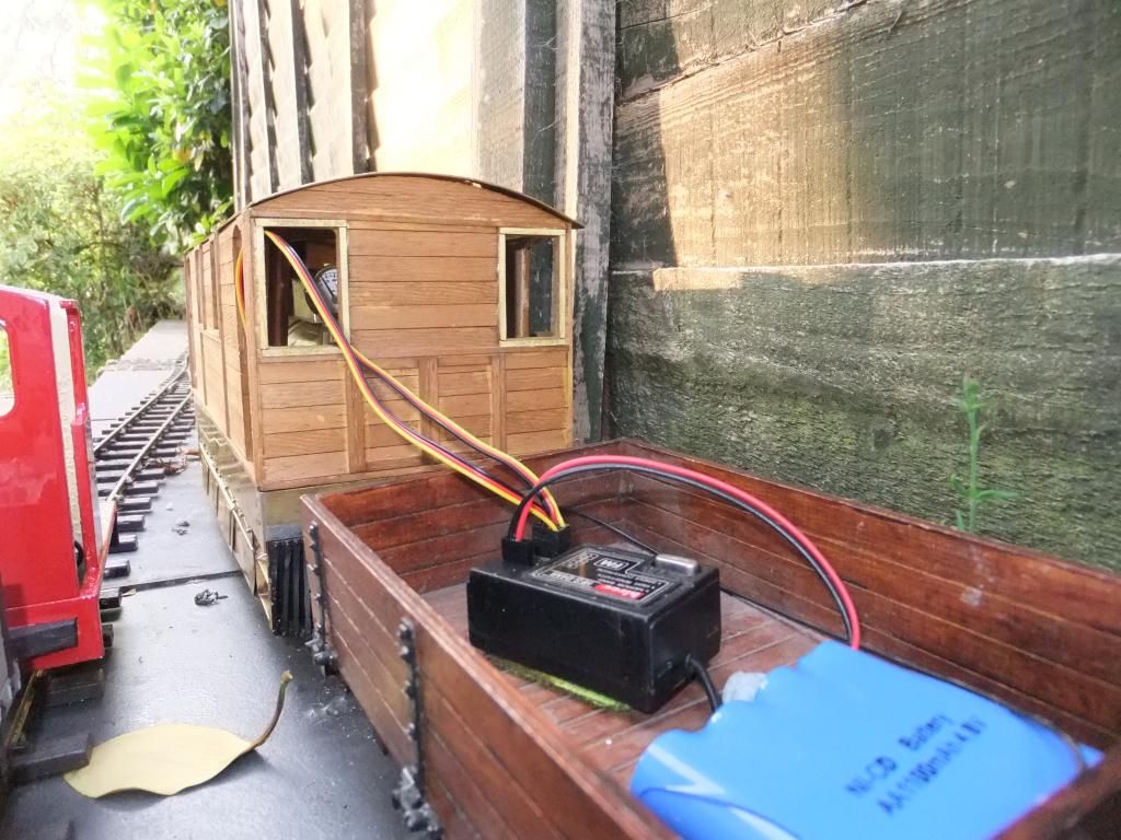
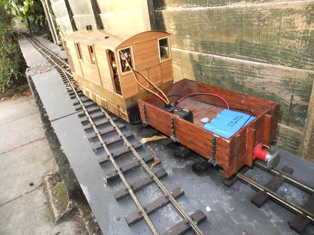
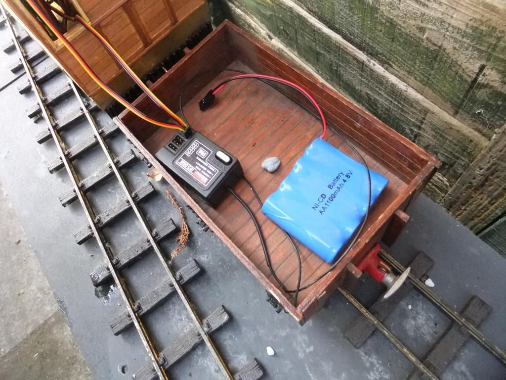
Last night I made a temporary battery and receiver mounting and installed all the kit semi permanently.
I have had an inaugural run today! I have captured some video footage of the event including a high speed run. By christ does this thing get a bloody shift on, it is scary! There is not much of it because I spend much of the time setting up the throttle linkage.
Below are some stills of the event. I am very happy with the way it is running now. The adjustments on the timing have help enormously. I am ready to drill and pin the cranks in position now.
Just a little taster.
Inital set up
Thu Aug 08, 2013 10:58 pm
Thanks for the comments Guys, very kind.
Now, here is the video. I had a fun time editing it.
Enjoy!
<object width="800" height="450"><param name="movie" value="//www.youtube.com/v/roAdxvFhavI?version=3 ... ram><param name="allowFullScreen" value="true"></param><param name="allowscriptaccess" value="always"></param><embed src="//www.youtube.com/v/roAdxvFhavI?version=3&hl=en_GB" type="application/x-shockwave-flash" width="800" height="450" allowscriptaccess="always" allowfullscreen="true"></embed></object>
Fri Aug 09, 2013 10:58 pm
Hehe, Thanks Chris. I have thought long and hard about the 'Toby' name, but I cannot see 'Toby' fitting at all. As great a name as it is. I want to remember Toby as the tram engine on the Thomas the tank series, not for one of mine.
I have finished editing and have now published the video of, what I call the 'Sensible Run', unlike yesterdays hooliganism that possessed me.
Some may say I have taken the 'direct line' we shall see. (UK joke) I figured that the soundtrack fitted ok, but if it isn't liked, please let me know and I shall change it for something a little more traditional.
<object width="800" height="450"><param name="movie" value="//www.youtube.com/v/dR_eLPk5rsE?version=3 ... ram><param name="allowFullScreen" value="true"></param><param name="allowscriptaccess" value="always"></param><embed src="//www.youtube.com/v/dR_eLPk5rsE?version=3&hl=en_GB" type="application/x-shockwave-flash" width="800" height="450" allowscriptaccess="always" allowfullscreen="true"></embed></object>
Wed Sep 25, 2013 10:04 pm
Right then,
Time for a small update. I am planning on taking this model to Elsecar if time allows so I thought I'd do some details I have been planning for some time.
First of all, do you guys think I should paint the section above the cow catcher in red just to break things up a bit?
here are