By heck Trevor that is an amazing bit of drawing, let alone actually making it all.
The wheelsets look fantastic, btw.
Little Wonder
Re: Little Wonder
Philip
Re: Little Wonder
I am totally envious of your skills and equipment. Those wheels look amazing.
Rik
Rik

Re: Little Wonder
Brilliant..... 
ROD
Life is so easy when I run my trains.


https://gardenrails.org/forum/viewtopic ... 41&t=11364
https://www.youtube.com/@fairywoodlightrailway
Life is so easy when I run my trains.


https://gardenrails.org/forum/viewtopic ... 41&t=11364
https://www.youtube.com/@fairywoodlightrailway
-
Trevor Thompson
- Trainee Driver

- Posts: 988
- Joined: Fri Oct 05, 2018 6:30 pm
- Location: South West Wales
Re: Little Wonder
I am fitting the first bogie with its axle boxes. Since I am going to spring the axles (not that the springs will bear the locos weight, but merely keep the wheels on the rail when the loco passes a dip in the track) I want to make the surface they run against a bit wider than the steel chassis. So the exlebox:
and the horn guide:
The first 4 axleboxes and horn guides have been milled, and 2 of them fitted:
I had intended to hold the guides with screws, but it seemed like a good idea to soft solder them on. The finished wheel sets will be removable and held in place by "keeper plates" screwed up into the horn guides:
Trevor
- Screenshot 2023-04-06 at 19.04.39.png (45.5 KiB) Viewed 6627 times
- Screenshot 2023-04-06 at 19.02.43.png (58.51 KiB) Viewed 6627 times
- IMG_2898.JPG (2.2 MiB) Viewed 6627 times
- IMG_2897.JPG (2.1 MiB) Viewed 6626 times
-
-steves-
- Administrator

- Posts: 2445
- Joined: Thu Jul 28, 2011 1:50 pm
- Location: Cambridge & Peterborough
Re: Little Wonder
16mm model engineering at it's best, a big well done so far for everything. All well outside of my humble capabilities, but it's awesome to see it all happening.

Re the wheel blanks. I followed some help from an old loco build I found once in a magazine, which I found online, these were for the Kerr Stuart Brazil, but all the same principles apply.
It's written by Keith Bucklitch and they can be found in the steammodelloco16mm.groups.io under their files section. Not sure if it's ok to post them here as I think you need to be in the group to read it, they are PDF documents. Don't get me wrong, clearly you don't need this Trevor, but if someone is reading and wants to give it a go, then it may be of help.
P.S. A lay down metal bandsaw has saved my arms and shoulders, many, many many times over and I would be lost without it.
The buck stops here .......
Ditton Meadow Light Railway (DMLR)
Member of Peterborough and District Association
http://peterborough.16mm.org.uk/
Ditton Meadow Light Railway (DMLR)
Member of Peterborough and District Association
http://peterborough.16mm.org.uk/
Re: Little Wonder
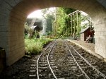
I really like how you've a set of rails on part of your workbench. It looks like a real erecting shop!
-
Trevor Thompson
- Trainee Driver
- Posts: 988
- Joined: Fri Oct 05, 2018 6:30 pm
- Location: South West Wales
Re: Little Wonder
Yes it can be really useful. It was intended as a place to test live steam locos before taking them up to the railway. It incorporates a number of curves set to the minimum radius on the railway.
However I do seem to start so many projects that it ends up with all the unfinished things cluttering it up.
Trevor
-
Trevor Thompson
- Trainee Driver
- Posts: 988
- Joined: Fri Oct 05, 2018 6:30 pm
- Location: South West Wales
Re: Little Wonder
After a concerted effort to get all of the suspension made and assembled I have a rolling chassis:
The next stage is to make the eccentrics and fit them to the axles. Before I can do that though I need to be sure about how the valve gear is going to work out. So some planning. The valve gear is a variation on Stephenson's Valve Gear where the expansion link is held still and the gear selected by moving the radius arm up and down instead. The Stephenson gear I used on Linda does get close to digging into the ballast, and just misses the boiler cladding, depending which gear it is in. Holding the expansion link still will avoid this.
A diagram to illustrate:
The axle with its eccentrics is on the left, with the eccentric followers and their shafts joining to the expansion link in the centre. I have drawn the expansion link as a straight link, rather than it following the radius of the radius arm. On the right is the front axle, with a bent radius arm reaching over the top of the front axle. I have drawn the radius arm twice, once in ahead and once in reverse, so I can be sure that it is sufficiently "bent" to always clear the front axle. The valve rod would be on the extreme left if I had included it in the drawing.
As with redesigning the valve gear for K1 I have referred to Don Ashton's book on designing valve gear - and of course the experience of designing Linda's Stephenson's valve gear.
I have learnt that the positioning of the suspension of the expansion link is critical. The length of the suspension link, and the position where it is suspended from are important. The book describes calculating these or or alternatively drawing it out to scale. I couldn't work out where that was leading so I made the electronic equivalent of a scale drawing in Sketchup. I just experimented with lengthening and shortening the suspension link to see what happened, and manually moving all of the links to see what changed. A couplings of evenings later I had this sketch:
Honestly it's not as bad as it looks at first sight. Just look at the top row for now. On the left is the valve sitting on top of the ports. On the right is a "Y" shaped "thing" which represents the offset of the eccentrics and the crank pin. The crank pin is sitting horezontaly to the right and the two eccentric centres are one over the other offset to the left of the axle centre. That offset is related to the "lap" . It just offsets the valve opening to make the valve open at top dead centre. In the middle is the expansion link as a skeleton and a rectangular box representing the suspension link. In this gear the suspension link is attached to the expansion link at the bottom. The radius arm is shown attached so far down from the top of the expansion link, and for the other gear the same amount from the bottom.
The top two diagrams show the linkage at top and bottom dead centre - the point is to make sure that the valve is just about to open - but that it hasn't already opened which would make it go backwards. I have drawn a radius arm in both forward and reverse positions and in these top two pictures you can see that the two valves are near enough one on top of the other.
The bottom two diagrams are to show that the valve opens the same amount in forward and reverse, and the same amount at when the crankpin is at the top and bottom of its travel. Again two radius arms and two valves, but the valves are overlapping in these diagrams. A bit less obvious but if you compare the valve in one of the top diagrams perhaps you can see that the valve is opening the same amount in ahead as in reverse - that is the important bit.
Having changed the length of the suspension arm, and moved where it pivots I think that the diagram now shows it "as good as I am going to get it". So I can measure the length of the suspension link and measure where it has to be suspended from - so that I can add extra holes into the chassis for a suspension rod. The suspension point needs to be 10.4mm above the line between the axle centres, and 40.4mm from the inner axle.
I think I can make the eccentrics next. However its time to give this a rest and work on other projects for a while.
Trevor
- IMG_2899.JPG (2.12 MiB) Viewed 6568 times
A diagram to illustrate:
- Screenshot 2023-04-12 at 16.41.36.png (34.66 KiB) Viewed 6568 times
As with redesigning the valve gear for K1 I have referred to Don Ashton's book on designing valve gear - and of course the experience of designing Linda's Stephenson's valve gear.
I have learnt that the positioning of the suspension of the expansion link is critical. The length of the suspension link, and the position where it is suspended from are important. The book describes calculating these or or alternatively drawing it out to scale. I couldn't work out where that was leading so I made the electronic equivalent of a scale drawing in Sketchup. I just experimented with lengthening and shortening the suspension link to see what happened, and manually moving all of the links to see what changed. A couplings of evenings later I had this sketch:
- Screenshot 2023-04-12 at 17.38.53.png (38.7 KiB) Viewed 6565 times
The top two diagrams show the linkage at top and bottom dead centre - the point is to make sure that the valve is just about to open - but that it hasn't already opened which would make it go backwards. I have drawn a radius arm in both forward and reverse positions and in these top two pictures you can see that the two valves are near enough one on top of the other.
The bottom two diagrams are to show that the valve opens the same amount in forward and reverse, and the same amount at when the crankpin is at the top and bottom of its travel. Again two radius arms and two valves, but the valves are overlapping in these diagrams. A bit less obvious but if you compare the valve in one of the top diagrams perhaps you can see that the valve is opening the same amount in ahead as in reverse - that is the important bit.
Having changed the length of the suspension arm, and moved where it pivots I think that the diagram now shows it "as good as I am going to get it". So I can measure the length of the suspension link and measure where it has to be suspended from - so that I can add extra holes into the chassis for a suspension rod. The suspension point needs to be 10.4mm above the line between the axle centres, and 40.4mm from the inner axle.
I think I can make the eccentrics next. However its time to give this a rest and work on other projects for a while.
Trevor
-
Trevor Thompson
- Trainee Driver
- Posts: 988
- Joined: Fri Oct 05, 2018 6:30 pm
- Location: South West Wales
Re: Little Wonder
A couple of spare hours and I have the first part of the valve gear created. This is what I am making:
It shows the 4 eccentrics which drive the valve gear. There is a carrier and 2 "cams" or eccentrics mounted on that carrier, in turn mounted on the axle. There are of course 2 of these side by side one for each cylinder. I have made the carrier with a boss to take a grub screw which will secure it to the axle so that it can be adjusted. Two eccentrics fit onto each carrier, and will be silver soldered into the correct orientation. I hope I can silver solder them without getting solder where I don't want it. I will have to make a jig to set the eccentrics at the correct angle to each other before soldering.
So here are the components made:
So the next job will be to drill and tap M2 for the grub screws, make the jig, and fit and solder them together.
Trevor
- Screenshot 2023-07-31 at 15.15.22.png (101.53 KiB) Viewed 6227 times
So here are the components made:
- IMG_3160.jpeg (1.25 MiB) Viewed 6227 times
Trevor
Re: Little Wonder
Strewth! 6 decimal places of millimetre precision!? Even with my 3D prints I'm happy with a 0.5mm tolerance..... 
Rik
Rik
-
Trevor Thompson
- Trainee Driver
- Posts: 988
- Joined: Fri Oct 05, 2018 6:30 pm
- Location: South West Wales
Re: Little Wonder
Just laziness - I could (and and perhaps should) alter the number of decimal places displayed!
I am happy with 0.2mm precision on something like this which is a tight fit into the available space.That is of course only attemptable because of the digital readout.
Trevor
I am happy with 0.2mm precision on something like this which is a tight fit into the available space.That is of course only attemptable because of the digital readout.
Trevor
-
Old Man Aaron

- Trainee Driver
- Posts: 824
- Joined: Wed Oct 19, 2016 11:08 am
- Location: Sunshine Coast QLD, Australia
Re: Little Wonder
Beautiful work as always. I machined a pair of bronze eccentrics for an Accy Ruby some years back. Simple one-piece objects - you're braver than I to jig up and solder yours! I'm sure they'll come up to your usual standard.
Regards,
Aaron - Scum Class Works
Aaron - Scum Class Works
-
Trevor Thompson
- Trainee Driver
- Posts: 988
- Joined: Fri Oct 05, 2018 6:30 pm
- Location: South West Wales
Re: Little Wonder
I have finally got back to this after a couple of months absence doing other things.
So I have set the eccentrics on to their carriers:
The carrier is 15mm diameter and the eccentrics are 16mm diameter. They were assembled using bearing lock and quickly pressed against a block of brass. By holding the carrier flat on the bench while pressing the three components against the brass, the eccentrics were locked in a position which will mean that the valve opens just after the piston has reached the end of its travel - in both ahead and reverse. When the motion is made and all connected each pair of eccentrics can be adjusted so that the valve timing is the same in both directions.
I thought I was going to silver solder the eccentrics, but the lock tight method seemed easier. Rather than rely on lock tight alone I have bored through all three components and fitted a clockmakers taper pin. I fixed that with bearing lock as well. So one set pinned, and the other pinned and filed up:
The eccentrics mounted on the axle, and all fitted to the frames:
Both bogies are in the same state - both have the eccentrics and axles in place. These two inboard wheels on each bogie are fixed to their axles with bearing lock, and quartered by eye. When the lock tight has cured I will drill and pin these wheels in place. The other axle can't have its wheels mounted permanently until the coupling rods are fitted.
So the eccentric straps are next, and I am working towards assembled valves and valve gear.
Trevor
So I have set the eccentrics on to their carriers:
- IMG_3617.jpeg (2.57 MiB) Viewed 4147 times
I thought I was going to silver solder the eccentrics, but the lock tight method seemed easier. Rather than rely on lock tight alone I have bored through all three components and fitted a clockmakers taper pin. I fixed that with bearing lock as well. So one set pinned, and the other pinned and filed up:
- IMG_3619.jpeg (2.01 MiB) Viewed 4147 times
- IMG_3618.jpeg (2.25 MiB) Viewed 4147 times
So the eccentric straps are next, and I am working towards assembled valves and valve gear.
Trevor
-
Old Man Aaron
- Trainee Driver
- Posts: 824
- Joined: Wed Oct 19, 2016 11:08 am
- Location: Sunshine Coast QLD, Australia
Re: Little Wonder
Suitably fiddly.
They're really packed in there, between those axleboxes.
They're really packed in there, between those axleboxes.
Regards,
Aaron - Scum Class Works
Aaron - Scum Class Works
Re: Little Wonder
Watchmaking comes to mind!Old Man Aaron wrote: ↑Fri Dec 29, 2023 12:53 pm Suitably fiddly.
They're really packed in there, between those axleboxes.
Philip
-
Trevor Thompson
- Trainee Driver
- Posts: 988
- Joined: Fri Oct 05, 2018 6:30 pm
- Location: South West Wales
Re: Little Wonder
While I was waiting for the materials to make the valve gear from I started working on the valves:
Milling the slots into one of the 4 valves. A 2 mm wide slot to take a 2mm diameter valve rod, and one at 90 degrees to take the threaded strip which moves the valve.
4 valve operating rods with their fittings to take the valve gear:
I have yet to make the strip which actually drives the valve. The fitting, locknut, and rod are tapped M2 (right hand thread). The valve end of the rod , and its strip are tapped M2 ( Left hand thread). The idea is that the adjustment of the valve can be done mainly turning the end fitting around, and then connecting it to the valve gear. The fine adjustment can then be done by slackening the locknut and turning the valve rod. With the opposing handed threads turning the rod will move the valve in and out.
and finally test fitting the first valve:
Well it all seems to fit, so on to actually assembling the pistons, cylinders and valves with gaskets before going back to the valve gear. It will be satisfying to see compressed air move the pistons in and out as the valves are moved.
Trevor
- IMG_3620.jpeg (2.22 MiB) Viewed 3471 times
4 valve operating rods with their fittings to take the valve gear:
- IMG_3622.jpeg (1.88 MiB) Viewed 3471 times
and finally test fitting the first valve:
- IMG_3621.jpeg (1.96 MiB) Viewed 3471 times
Trevor
-
-steves-
- Administrator
- Posts: 2445
- Joined: Thu Jul 28, 2011 1:50 pm
- Location: Cambridge & Peterborough
Re: Little Wonder
Great work as always Trevor, still loving the "live" photos 
The buck stops here .......
Ditton Meadow Light Railway (DMLR)
Member of Peterborough and District Association
http://peterborough.16mm.org.uk/
Ditton Meadow Light Railway (DMLR)
Member of Peterborough and District Association
http://peterborough.16mm.org.uk/
-
Trevor Thompson
- Trainee Driver
- Posts: 988
- Joined: Fri Oct 05, 2018 6:30 pm
- Location: South West Wales
Re: Little Wonder
The first bogie now has its valves fitted permanently (hopefully!). Each cylinder has its end covers fitted using a lock tight gasket fluid. The cylinders are also fixed to the frame using the same sealant. The valve stems are in roughly the correct setting, and it is all assembled:
The cover has been fitted with a paper gasket, and the holes drilled out for fixing it in place.
The steam intake is a third fitting which is just visible below the valve guides in both photos. The exhaust will be made from 3mm copper pipe and will exit the cylinders at the top between the frames before being joined together. The details of how that will work will be clearer (to me) once the boiler is made. So the front end assembled and steam tight:
I have tried it out on 25 psi with the air line, and I can confirm that each piston shoots in and out as the appropriate valve is moved.It is reassuring to see that the valve stems clear the front axle! So, apart from having lost a couple of half made automatic valves, I can repeat all of this on the second bogie.
Trevor
- IMG_3629.jpeg (2.31 MiB) Viewed 3238 times
The steam intake is a third fitting which is just visible below the valve guides in both photos. The exhaust will be made from 3mm copper pipe and will exit the cylinders at the top between the frames before being joined together. The details of how that will work will be clearer (to me) once the boiler is made. So the front end assembled and steam tight:
- IMG_3634.jpeg (2.3 MiB) Viewed 3236 times
Trevor
- Attachments
-
- IMG_3632.jpeg (1.78 MiB) Viewed 3238 times
-
Trevor Thompson
- Trainee Driver
- Posts: 988
- Joined: Fri Oct 05, 2018 6:30 pm
- Location: South West Wales
Re: Little Wonder
Today I started to make the expansion links. I am making them out of 3mm thick mild steel, so that involved coolant oil, and one of my rotary tables. This one has a flat bed which I can fix metal strips onto. The metal was held down so that the centre of the strip was 42.5mm from the centre of the table. That gives the expansion link the correct radius.
The drawing:
Having set up the table so that the centre of the milling head was lined up with the centre of the rotary table, I just had to move the X axis the 42.5mm to set the radius. All the milling and drilling can then be controlled by rotating the table. Milling the slot:
The finished slot and the holes to take the eccentric rods. I then milled out the outline of the link.
I have diverged slightly from the drawing - in that the slot is 3mm wide not 2mm wide - I think that will make it easier to make the block which slides up and down in the slot.
The first expansion link finished:
Trevor
The drawing:
- Screenshot 2024-01-16 at 10.16.18.png (79 KiB) Viewed 2943 times
- IMG_3640.jpeg (2.57 MiB) Viewed 2943 times
- IMG_3642 2.jpeg (2.14 MiB) Viewed 2943 times
The first expansion link finished:
- IMG_3643.jpeg (1.86 MiB) Viewed 2924 times
-
Trevor Thompson
- Trainee Driver
- Posts: 988
- Joined: Fri Oct 05, 2018 6:30 pm
- Location: South West Wales
Re: Little Wonder
I now have 4 completed expansion links:
and I have started on the eccentric straps. This is what I am trying to create:
and a detail:
I started off hacksawing out 8 off 25mm square blanks, and drilling an 8mm diameter hole into each of them. That enabled me to mount two of them at a time in one of the mandrills I use for making wheels:
The next task is to turn the outside diameter down to 24mm diameter. I hope to then be able to mill out the slots and drill and tap the holes (10BA) which will hold the two halves of the eccentric strap together. Then I plan to saw the two halves apart, clean up the sawcut and bolt the halves together. Hopefully I can then hold each strap in the chuck while I turn the inside diameter to size.We will see if it works! Then I have to repeat it 7 more times.
Turning the outside diameter to size:
Trevor
- IMG_3649.jpeg (2.27 MiB) Viewed 2706 times
- Screenshot 2024-01-23 at 18.51.49.png (118.17 KiB) Viewed 2706 times
- Screenshot 2024-01-23 at 18.48.13.png (70.86 KiB) Viewed 2706 times
- IMG_3650.jpeg (2.32 MiB) Viewed 2706 times
Turning the outside diameter to size:
- IMG_3651.jpeg (2.26 MiB) Viewed 2706 times
Who is online
Users browsing this forum: No registered users and 2 guests