Thanks for the comments guys, I think I have teased and confused you just about enough now so more can be revealed...
I showed progress in advance of installing the forward pair of wheels underneath the wings of the bonnet assembly, so the cab will be a four wheeled vehicle, not just two as previously shown.... soon!
The separate vehicles must be flexible enough to allow for horizontal and vertical movement and slight tilt between them in order to stay on track. To achieve this I have fitted a 'Rose' bearing...

- IMG_8792.JPG (134.94 KiB) Viewed 3062 times
This gives the necessary movement in all directions....

- IMG_8790.JPG (92.53 KiB) Viewed 3062 times

- IMG_8789.JPG (89.8 KiB) Viewed 3062 times
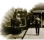
The major difference to the earlier images is that the finished vehicle will look like this....

- IMG_8788.JPG (88.39 KiB) Viewed 3062 times
So, in answer to Lonsdaler's question about turning radius, it will be able to do this....

- IMG_8787.JPG (87.63 KiB) Viewed 3062 times
The only wheels will be on the two driving cabs with the carriage suspended from them. In order to maintain level working one cab has a flat surface which pivots and lifts, whilst the other end does all the twisting etc. to cope with track undulations...

- IMG_8793.JPG (92.06 KiB) Viewed 3062 times
I hope that make it all clear now, but I might not have explained the action too well as my engineering experience is minimal.
The best things in life are free.... so why am I doing this?