
The thing I noticed was that the SV dome over the dome appears to be shiny steel and not brass as I might have expected - although I did wonder how they'd keep brass polished in the environment it's working in.
Interestingly, blowing the picture up to 500%, brings out colour subtleties even more and you can see that on the backhead the pipes have a coppery sheen and the fittings look to be brass, all of which you might expect as well, of course.
Contractors Loco Project
Re: Contractors Loco Project
Philip
-
Trevor Thompson
- Trainee Driver

- Posts: 988
- Joined: Fri Oct 05, 2018 6:30 pm
- Location: South West Wales
Re: Contractors Loco Project
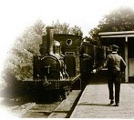
I think that the clothes look entirely plausible as well. Blue Cotton work clothes were the norm and they faded rapidly with washing. So the various shades of blue with dirt layered on top seem correct to me. As does the hint of more colour in the drivers neck cloth. Really amazing colourisation !
Re: Contractors Loco Project
That's incredible. How on earth does the algorithm differentiate between copper and brass? I thought it was clever being able to recognise flesh and clothes, but reacting to steam fittings takes it to another level
Rik

Re: Contractors Loco Project
My guess is this is all simply machine learning. The system has a bunch of photographs of copper and/or brass that have been correctly identifies, and tries to extrapolate. Getting the overalls the correct colour is probably easy - lots of similar photographs to provide the data. What the algorithm almost certainly won't have been able to do is identify that this is a locomotive, because I can't imagine it has (m)any other locomotives in its database that look remotely similar. But it will have lots of pictures of copper pipes, and brass fittings, that look similar enough to copy the colours for.
Re: Contractors Loco Project
Not sure it will have ANY loco's in it's database, given that its purpose is to colourise vintage photo's of people. 
Anyway, this is the colourised photo blown up to 500%.
The difference between copper pipes,brass fittings and steel hand wheel shafts is clear.
Anyway, this is the colourised photo blown up to 500%.
- Screenshot 2022-01-13 13.04.26.png (1.02 MiB) Viewed 2398 times
Philip
Re: Contractors Loco Project
There's even a hint of rust on the backplate - incredible!
Rik
Rik

Re: Contractors Loco Project
It's quite incredible how colourisation has added a whole new dimension to that photograph, and made it appear so much more 'real'. Regarding recognition of copper/brass etc. I would think that the geneology site simply pays to use a commercially available product rather than run their own system, so it will in fact have a lot of examples to draw upon to produce believable results - after all, we will never know if it's accurate or not. Anyway, as I said - incredible 
Phil
Sporadic Garden Railer who's inconsistencies know no bounds
My Line - https://gardenrails.org/forum/viewtopic ... 41&t=11077
Sporadic Garden Railer who's inconsistencies know no bounds
My Line - https://gardenrails.org/forum/viewtopic ... 41&t=11077
Re: Contractors Loco Project
Okey doke, having done colourisation to death, more or less, back to the model. 
Unless somebody tells me differently, I've decided on the water tank. I have a 6v motor, so that requires 5 x 1.2v cells. I was originally thinking less than that and was thinking of a box holding 4 side by side, disguised as a water tank against the back wall. 5 cells would require 2 rows... 3+2) which makes the box quite bulky. Then Graeme made a passing comment about the tank possibly doubling as the drivers seat and that got me thinking. A realistic sized seat would only hold 2 cells, one above the other, laying across the body and it needs a home for three more somewhere. I've now got the motor position firmed up inside the coal bunker and that just leaves room for two cells one above the other in front of the motor, and the last one alongside them, over the top of the motor. I think that just leaves space for a charging socket and an on/off switch.
Obviously the tank needs a lid! By my calculations, this tank would hold approx 130gals
Unless somebody tells me differently, I've decided on the water tank. I have a 6v motor, so that requires 5 x 1.2v cells. I was originally thinking less than that and was thinking of a box holding 4 side by side, disguised as a water tank against the back wall. 5 cells would require 2 rows... 3+2) which makes the box quite bulky. Then Graeme made a passing comment about the tank possibly doubling as the drivers seat and that got me thinking. A realistic sized seat would only hold 2 cells, one above the other, laying across the body and it needs a home for three more somewhere. I've now got the motor position firmed up inside the coal bunker and that just leaves room for two cells one above the other in front of the motor, and the last one alongside them, over the top of the motor. I think that just leaves space for a charging socket and an on/off switch.
- Screenshot 2022-01-13 18.36.56.png (33.5 KiB) Viewed 2885 times
Philip
Re: Contractors Loco Project
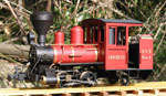
Now we are getting somewhere 
Basic body put together,
Chassis running but still needs the chain to the rear axle.
The water tank battery box is still loose but in position.
The boiler is still loose but in position.
The engine is still loose but approx in position.
The dome is loose but in approx position.
Plenty more small details need adding, inluding the smokebox and chimney on the far side and some pipework on the boiler backhead and inside the cab.
Before anyone says anything, the axles are in the correct position as near as I can tell, but I think the original must have been std gauge, or 4ft, or something along those lines, and the perspective of 32mm is making them appear too far forward.
For general info, the two different shades of grey show which bits were FMD printed and which were resin.
Basic body put together,
Chassis running but still needs the chain to the rear axle.
The water tank battery box is still loose but in position.
The boiler is still loose but in position.
The engine is still loose but approx in position.
The dome is loose but in approx position.
Plenty more small details need adding, inluding the smokebox and chimney on the far side and some pipework on the boiler backhead and inside the cab.
- DSC_0003.JPG (4.47 MiB) Viewed 2853 times
For general info, the two different shades of grey show which bits were FMD printed and which were resin.
Philip
Re: Contractors Loco Project
The steam engine is small, as is the boiler, so the loco wouldn't have used water at a very high rate and I suspect 130 gallons would be plenty. As a comparison, the water tank on a Kerr Stuart Wren is only 87 gallons and they are a larger loco.
The battery layout must be right, as that's how I'd have laid it out......
You'll find out when you get the chassis working and can do some test running, but you may only need 4 cells. My gang motor is about that size and has a 6V N20 motor with a 50:1 gearbox. With 20mm dia. wheels and 4 cells (4.8V nominal) it toddles around the track at about 11 scale mph. I can't see a home made contractors loco being any threat to City of Truro.......
Yes, definitely getting somewhere. I assume the engine is a resin print, as I wouldn't have thought a filament printer would manage parts that fine.
3' gauge was commonly used for reservoir projects for some reason and that may be the gauge of the prototype. My 3' gauge Hunslet 0-4-0ST is based on a loco that was used by the Fyld Water Board on a reservoir project.
Graeme
Re: Contractors Loco Project
Ah, thats interesting, mine is also an N20 with 48:1, so not much difference.. I was originally planning on 4.8v, but then I realised that the controller requires a min 4.8v and the motor was sold as being 6v, hence the increase. I've zoomed it up and down a short piece of track on the bench and it is a tad fast on 6v, but then again with some weight on and a train of skips behind, the extra umph might be useful.GTB wrote: ↑Fri Jan 14, 2022 11:38 am
You'll find out when you get the chassis working and can do some test running, but you may only need 4 cells. My gang motor is about that size and has a 6V N20 motor with a 50:1 gearbox. With 20mm dia. wheels and 4 cells (4.8V nominal) it toddles around the track at about 11 scale mph. I can't see a home made contractors loco being any threat to City of Truro.......
The wheels, boiler, engine, and the back wall behind the boiler are resin, the rest is all fdm. The back wall is resin because it is faced with bolted, overlapped, thin iron sheets. I tried filament with no great expectations and ended up with steps as the angle changed, which is what I expected. Finally I printed the 4 sheets as flat resin panels with bolts, with 0.5mm difference in thickness between successive panels and superglued them edge to edge, then mounted them with the outer face vertical in the fdm printed frame. It gives a kind of shiplap appearance but it's too fine to be noticeable.
Philip

Re: Contractors Loco Project
Looking good Philip!
It's a little thing, but I love how you've modelled the coal hatch slightly open...
It's a little thing, but I love how you've modelled the coal hatch slightly open...
Re: Contractors Loco Project
I've not got a resin printer though I'd like one. The benefits in terms of detail are plain to see. But I'm curious - for a part that needs some strength and will get some wear, like the wheels, how does a resin print compare to filament?
-
Peter Butler

- Driver

- Posts: 5266
- Joined: Sun Sep 09, 2012 10:33 pm
- Location: West Wales
Re: Contractors Loco Project
I had thought about building one myself, but you have just gone ahead and done it, brilliant! I'm speechless about the passion and dedication you have had for this project and managed to work out the finer points. I have to admit to little understand of how a steam engine works, so could never have achieved the detail you have created... superb work there.
The best things in life are free.... so why am I doing this?
Re: Contractors Loco Project
I can't really answer that one I'm afraid Simon. The only other resin wheels I've printed were for the Wickham Trolley and that has just rolled up and down a few yards, occasionally. There are quite a few different resins available with differing properties. In my experience the 'normal' ones tend to be a bit brittle but I saw one recently on Amazon that claimed to be similar to ABS and I was going to get some to try. Then I saw a lot of reviews saying that it used to be very good but had suddenly changed and was now a waste of money...!
I believe that Steve has quite a bit of experience with printed wheels so he can probably be more informative.
Philip
Re: Contractors Loco Project
Thanks for the compliments Peter.Peter Butler wrote: ↑Fri Jan 14, 2022 2:25 pm I'm speechless about the passion and dedication you have had for this project and managed to work out the finer points. I have to admit to little understand of how a steam engine works, so could never have achieved the detail you have created... superb work there.
To be honest, a lot of the detail has come from Graeme( GTB), he knows about such things as steam launch vertical engines and could recognise bits that were just faint lines on an old photo to me. Once he pointed them out it was, relatively speaking, obvious of course!
Philip
Re: Contractors Loco Project
I've been playing again, just to se what I could do, although it is relevant.
I said earlier that printing the backhead pipework didn't work, but I wondered if I could print the individual components, and this is the result ( obviously some cleaning up required).
The LH one is a 4mm diam handwheel, the centre one is 5mm and the lever one is the same basic body.
All have a 1mm diam hole both sides for pipe entry.
Given how exposed the backhead is on this loco, I'm not sure these will be robust enough to actually use. I suspect that with a few mins the hand wheels would get knocked off.
I said earlier that printing the backhead pipework didn't work, but I wondered if I could print the individual components, and this is the result ( obviously some cleaning up required).
The LH one is a 4mm diam handwheel, the centre one is 5mm and the lever one is the same basic body.
All have a 1mm diam hole both sides for pipe entry.
- DSC_0003.JPG (127.32 KiB) Viewed 2657 times
Philip
Re: Contractors Loco Project
I'm impressed that you made those with a consumer grade printer......
The valve spindles will be the vulnerable point, as acrylics are brittle. Are there more flexible resins available?
Or, do you have a manufacturing jeweller in your area? I've seen prints used for lost wax casting by investing the print itself, instead of using it as a pattern to make waxes.
Graeme
Re: Contractors Loco Project
I saw one recently on Amazon that claimed to be similar to ABS and I was going to get some to try. Then I saw a lot of reviews saying that it used to be very good but had suddenly changed and was now a waste of money...!
As for casting, we are only an hour or so from the famous Jewellery Quarter in Brum, but to get the few that I need for this, it really isn't worth the time and money to go that route I'm afraid. Good thought though.
I think what I'll probably do is print a few handles with a central hole and glue them to pieces of wire mounted in holes drilled in the backhead. A blob of glue will then look enough like the valve body to get away with it when all painted.
Philip
Who is online
Users browsing this forum: No registered users and 2 guests