Mitch
TVT - First Turnout and Infrastructure
-
Mitch stack
- Trainee Fireman

- Posts: 233
- Joined: Tue Sep 05, 2017 9:43 am
- Location: Australia
Re: TVT - First Turnout Completed
Marvelous Work Graeme., Looks absolutely fantastic especially the point levers! I hope you have been looking at progress on my little Tramway.
Mitch
Mitch
Mitch - Cockatoo Creek Tramway
Re: TVT - More Infrastructure (was First Turnout Completed)
Due to the local topography, my house is cut into the ground and the back part of the block is raised about 1m above the path around the house, with steps for access. This is where most of the TVT mainline will be located, so a removable bridge over the steps is needed to allow access to the area inside the track.
I decided on a Pratt Truss type, based on one in an article in Garden Rail Issue 212. The VR built very few of this type of bridge, preferring to use either timber trestles, or decked plate girder bridges for long spans and there was nothing like it on the VR NG lines. I like them though and they were common in NSW, so it is assumed the Works Engineer worked on the NSWGR, before joining the TVT......
The area I live is a declared subterranean termite area (they don't build mounds around here, the nests are completely underground), so metal construction is a good idea in any case. The bridge was constructed from extruded aluminium angle from the local Mitre 10, bolted together with stainless steel M3 bolts and nuts, so it should outlast me. Strength is more than adequate for the job, but it weighs only 5kg, which is less than the Garratt and the large tender locos., so removing it for access is easy.
Some marketing 'genius' has recently changed the length of the longer aluminium extrusions in the local hardware stores from 2m to 3m and it was a tight squeeze to get them into the car. The width of the steps dictated that the bridge needed to be 1.6m long, so too long to build out of the more easily handled 1m lengths.
The first photo shows the base assembled. The track is designed to locate between two 20mm x 1.5mm angles and a piece of AMS sleeper strip can be seen checking that it will indeed fit. The lower chord of the truss is made from 25mm x 3mm angle, as are the cross members. The walkways along the side of the track are 32mm x 3mm flat. A VR bridge would be decked and ballasted, but I decided against doing that.
The next photo shows one of the side trusses being erected, with some parts bolted in place and others still clamped as work progresses. The top chord and vertical braces are 20mm x 1.5mm angle. The braces were drilled and the ends tapered, then clamped in place with toolmakers clamps to be used to drill the holes in the top and bottom chord angles. Much easier to keep everything square that way.
The third photo shows the bridge with both side trusses installed, the 20mm x 1.5mm top cross braces in place and the 12mm x 1.5mm angle braces in the truss being installed. The bridge became noticeably much stiffer once the angled braces were installed in the trusses and there was no visible deflection when the bridge was supported only at the ends and I pressed down hard. It won't notice the weight of the Garratt, or the local brushtail possum and cat populations if it comes to that.
The next photo shows the side trusses complete, but the 12mm x 1.5mm angle braces on the top and bottom still need to be added. While the bridge was now rigid vertically, the horizontal and torsional strength was still low.
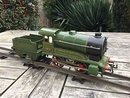
The next photo shows the bridge fully assembled, with the Hunslet loco sitting on a short piece of track to provide an idea of the scale of the bridge. This is by far the largest model I've built since changing scale and it barely fits on the workbench. With the angle braces in place on the top and bottom, the bridge was now as strong torsionally as it was under vertical and horizontal loads.
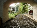
The sun was out today and the next photo shows the bridge outside in late afternoon sunshine spanning the steps up to the back of the block. It is sitting on bricks to bring it up to about the same height above the path that it will occupy when the track is installed. Interestingly it looks a lot smaller in place than it does inside on the workbench. The only job left now is to paint it, which can wait until it is installed.
The last photo shows the tools used for this project. This is here to show you don't need much in the way of workshop equipment for this sort of project. The only machine tool used was the bench drill when drilling some of the boltholes, everything else was fabricated with hand tools. The skills needed weren't much different to woodworking.
There was no space left on the workbench once the bridge assembly started, so all the tools had to sit on the small side bench I normally use for metal work. Cutting parts to length and shaping the ends was done with the piercing saw and cleaned up with files. While aluminium extrusions can be cut with a woodworking bandsaw, the parts were all too long to fit my little 6" bandsaw. The same with drilling holes, small parts were drilled with the bench drill, but the long parts were too large and unwieldy for that, so the finished small parts were clamped in place and used as templates to drill the long parts using the battery drill.
Regards,
Graeme
I decided on a Pratt Truss type, based on one in an article in Garden Rail Issue 212. The VR built very few of this type of bridge, preferring to use either timber trestles, or decked plate girder bridges for long spans and there was nothing like it on the VR NG lines. I like them though and they were common in NSW, so it is assumed the Works Engineer worked on the NSWGR, before joining the TVT......
The area I live is a declared subterranean termite area (they don't build mounds around here, the nests are completely underground), so metal construction is a good idea in any case. The bridge was constructed from extruded aluminium angle from the local Mitre 10, bolted together with stainless steel M3 bolts and nuts, so it should outlast me. Strength is more than adequate for the job, but it weighs only 5kg, which is less than the Garratt and the large tender locos., so removing it for access is easy.
Some marketing 'genius' has recently changed the length of the longer aluminium extrusions in the local hardware stores from 2m to 3m and it was a tight squeeze to get them into the car. The width of the steps dictated that the bridge needed to be 1.6m long, so too long to build out of the more easily handled 1m lengths.
The first photo shows the base assembled. The track is designed to locate between two 20mm x 1.5mm angles and a piece of AMS sleeper strip can be seen checking that it will indeed fit. The lower chord of the truss is made from 25mm x 3mm angle, as are the cross members. The walkways along the side of the track are 32mm x 3mm flat. A VR bridge would be decked and ballasted, but I decided against doing that.
- Bridge-1.jpg (142.65 KiB) Viewed 5049 times
The next photo shows one of the side trusses being erected, with some parts bolted in place and others still clamped as work progresses. The top chord and vertical braces are 20mm x 1.5mm angle. The braces were drilled and the ends tapered, then clamped in place with toolmakers clamps to be used to drill the holes in the top and bottom chord angles. Much easier to keep everything square that way.
- Bridge-2.jpg (133.24 KiB) Viewed 5049 times
The third photo shows the bridge with both side trusses installed, the 20mm x 1.5mm top cross braces in place and the 12mm x 1.5mm angle braces in the truss being installed. The bridge became noticeably much stiffer once the angled braces were installed in the trusses and there was no visible deflection when the bridge was supported only at the ends and I pressed down hard. It won't notice the weight of the Garratt, or the local brushtail possum and cat populations if it comes to that.
- Bridge-3.jpg (142.41 KiB) Viewed 5049 times
The next photo shows the side trusses complete, but the 12mm x 1.5mm angle braces on the top and bottom still need to be added. While the bridge was now rigid vertically, the horizontal and torsional strength was still low.
- Bridge-4.jpg (149.53 KiB) Viewed 5049 times
The next photo shows the bridge fully assembled, with the Hunslet loco sitting on a short piece of track to provide an idea of the scale of the bridge. This is by far the largest model I've built since changing scale and it barely fits on the workbench. With the angle braces in place on the top and bottom, the bridge was now as strong torsionally as it was under vertical and horizontal loads.
- Bridge-5.jpg (128.61 KiB) Viewed 5049 times
The sun was out today and the next photo shows the bridge outside in late afternoon sunshine spanning the steps up to the back of the block. It is sitting on bricks to bring it up to about the same height above the path that it will occupy when the track is installed. Interestingly it looks a lot smaller in place than it does inside on the workbench. The only job left now is to paint it, which can wait until it is installed.
- Bridge-6.jpg (197.89 KiB) Viewed 5049 times
The last photo shows the tools used for this project. This is here to show you don't need much in the way of workshop equipment for this sort of project. The only machine tool used was the bench drill when drilling some of the boltholes, everything else was fabricated with hand tools. The skills needed weren't much different to woodworking.
There was no space left on the workbench once the bridge assembly started, so all the tools had to sit on the small side bench I normally use for metal work. Cutting parts to length and shaping the ends was done with the piercing saw and cleaned up with files. While aluminium extrusions can be cut with a woodworking bandsaw, the parts were all too long to fit my little 6" bandsaw. The same with drilling holes, small parts were drilled with the bench drill, but the long parts were too large and unwieldy for that, so the finished small parts were clamped in place and used as templates to drill the long parts using the battery drill.
- Bridge-7.jpg (136.89 KiB) Viewed 5049 times
Regards,
Graeme

Re: TVT - First Turnout Completed
Very impressive Sir!
Looking forward to seeing the bridge in situ, how long do you reckon we might have to wait?
Looking forward to seeing the bridge in situ, how long do you reckon we might have to wait?
Philip

Re: TVT - First Turnout Completed
Really nice work Graeme a brilliant looking turnout and a nicely modelled girder bridge 
Kevin

Re: TVT - First Turnout Completed
You've been busy again. Running by Christmas then!!!
Grant.
Grant.
Re: TVT - First Turnout Completed
Nice job there Graeme.
Is that were it’s going to be placed…
Is that were it’s going to be placed…
ROD
Life is so easy when I run my trains.


https://gardenrails.org/forum/viewtopic ... 41&t=11364
https://www.youtube.com/@fairywoodlightrailway
Life is so easy when I run my trains.


https://gardenrails.org/forum/viewtopic ... 41&t=11364
https://www.youtube.com/@fairywoodlightrailway
Re: TVT - First Turnout Completed
Great looking bridge, Graeme. Good to see the workshop that produced it too. Gives we non-engineers hope and reassurance.
Rik
Rik
Re: TVT - First Turnout Completed
There was a sign on a wall of the engineering office near my lab. 'Last week I couldn't spell injunear, now I are one.'
Actually, I studied science and spent my working life in a laboratory. I'm more a self-taught tradesman than an engineer, so yes there is hope for non-engineers.
Regards,
Graeme
Re: TVT - First Turnout Completed
Wow.... that's spooky! I was in London at the weekend and popped into Foyles Bookshop. I found a Christmas present there for my brother who used to be a mechanical engineer (initially working on large diesel engines for Davy Paxman). The strapline on the back of the book is very similar ......
- CCI15102018.jpg (55.98 KiB) Viewed 4949 times
- CCI15102018_0001.jpg (66.32 KiB) Viewed 4949 times
-
Mitch stack
- Trainee Fireman
- Posts: 233
- Joined: Tue Sep 05, 2017 9:43 am
- Location: Australia
Re: TVT - First Turnout and Infrastructure
Great work on the Truss Bridge Graeme. Hope to see your line up and running in the future.
Mitch
Mitch
Mitch - Cockatoo Creek Tramway
Re: TVT - First Turnout and Infrastructure
One more step on the road to a running track.........
AMS (Accucraft) 45mm ng track isn't currently available in assembled form here in Oz. I was able to get an unused box of assembled track from a friend of Grant, but phase 1 of the track needs more than 60', so I also had to lay in a supply of rail and sleeper strips and assemble the rest myself. AMS code 250 rail comes in 5' lengths and the sleeper strips are 12" long with 11 sleepers.
Some experimentation showed that threading the sleepers on the rail took a fair bit of force and a lot of time, so I ended up building a simple wooden jig that would hold the sleepers square and at the right spacing, while the rail was pushed through the moulded spikes and sleeper plates.
The first photo shows the jig in use. It is simply two pieces of wood with cleats nailed on at sleeper spacing. The longer piece is gripped in the bench vice, then the rails are slid into a sleeper strip and that assembly clamped in place. The shorter piece slides on a couple of bits of wood clamped to the bench. It is loaded with a strip of sleepers and pushed into place so the sleepers slide over the rail. Then repeat until all five sleeper strips are in place.
It might have been a bit easier if the rail was lubricated, but I didn't have any of the soap solution used when fitting tyres to wheel rims and a petroleum based lube could well attack the plastic rail fixings over time.
The second photo shows the result of two afternoons work with the assembly jig stacked on the workbench. There are 15 lengths of track in the pile, so about half the track needed for the mainline loop, if my maths is right. The rest is in a box under the bench, so the next step is putting posts in the ground.........
Regards,
Graeme
AMS (Accucraft) 45mm ng track isn't currently available in assembled form here in Oz. I was able to get an unused box of assembled track from a friend of Grant, but phase 1 of the track needs more than 60', so I also had to lay in a supply of rail and sleeper strips and assemble the rest myself. AMS code 250 rail comes in 5' lengths and the sleeper strips are 12" long with 11 sleepers.
Some experimentation showed that threading the sleepers on the rail took a fair bit of force and a lot of time, so I ended up building a simple wooden jig that would hold the sleepers square and at the right spacing, while the rail was pushed through the moulded spikes and sleeper plates.
The first photo shows the jig in use. It is simply two pieces of wood with cleats nailed on at sleeper spacing. The longer piece is gripped in the bench vice, then the rails are slid into a sleeper strip and that assembly clamped in place. The shorter piece slides on a couple of bits of wood clamped to the bench. It is loaded with a strip of sleepers and pushed into place so the sleepers slide over the rail. Then repeat until all five sleeper strips are in place.
- Track-1.jpg (152.74 KiB) Viewed 6486 times
It might have been a bit easier if the rail was lubricated, but I didn't have any of the soap solution used when fitting tyres to wheel rims and a petroleum based lube could well attack the plastic rail fixings over time.
The second photo shows the result of two afternoons work with the assembly jig stacked on the workbench. There are 15 lengths of track in the pile, so about half the track needed for the mainline loop, if my maths is right. The rest is in a box under the bench, so the next step is putting posts in the ground.........
- Track-2.jpg (172.63 KiB) Viewed 6486 times
Regards,
Graeme
Last edited by GTB on Sat Oct 27, 2018 2:31 pm, edited 1 time in total.
Re: TVT - First Turnout and Infrastructure
Most impressive Graeme.
What sort of timescale do you have in the back of your mind?
What sort of timescale do you have in the back of your mind?
Philip
-
tom_tom_go

- Driver

- Posts: 4824
- Joined: Wed Feb 23, 2011 3:08 am
- Location: Kent, UK
- Contact:
Re: TVT - First Turnout and Infrastructure
That track looks huge to the Peco SM32 stuff I use!
-
BorisSpencer
- Fireman

- Posts: 251
- Joined: Thu Apr 05, 2018 2:36 pm
- Location: East Northants
Re: TVT - First Turnout and Infrastructure
But what I'd give for 5ft lengths!
Re: TVT - First Turnout and Infrastructure
Must say Graeme, thats very impressive indeed. They do look far superior to the ready bought stuff….Bet they are far cheaper too.
ROD
Life is so easy when I run my trains.
https://gardenrails.org/forum/viewtopic ... 41&t=11364
https://www.youtube.com/@fairywoodlightrailway
Life is so easy when I run my trains.
https://gardenrails.org/forum/viewtopic ... 41&t=11364
https://www.youtube.com/@fairywoodlightrailway
Re: TVT - First Turnout and Infrastructure
That does look good, Graeme.
I wish now that I had constructed my railway from code 250 track - bog standard code 332 LGB rail looks far too heavyweight for a light railway by comparison.
Rik
I wish now that I had constructed my railway from code 250 track - bog standard code 332 LGB rail looks far too heavyweight for a light railway by comparison.
Rik
-
Mitch stack
- Trainee Fireman
- Posts: 233
- Joined: Tue Sep 05, 2017 9:43 am
- Location: Australia
Re: TVT - First Turnout and Infrastructure
Great work graeme! Hope to see more on your railway soon.
Mitch
Mitch
Mitch - Cockatoo Creek Tramway
Who is online
Users browsing this forum: No registered users and 3 guests