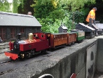
As mentioned above, I have been working on some electric powered locomotive projects and decided to build my own chassis. before we continue I should say I am not an engineer.
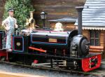
I think it all began when I purchased this on ebay...

Previously I had concern about motors, gearboxes and meshing issues. However, after seeing this method I decided to have a go myself. Searching for suitable motors on the 'net I discovered a motor with built-in reduction gearbox (available in 15:1, 30:1 or 100:1 ratios) for only £11.00 and a further search found nylon bevel gears in a variety of axle sizes and reductions.
I made the side frames from aluminium flat fixed together with spacers from Roundhouse. The wheelsets are on shouldered axles to set the gauge and run in brass bearings.
The first job was to devise a way of connecting the two axles to make four wheel drive. My chassis will be hidden from view so a connecting drive using a shaft was adopted. The shaft is held firmly in place by means of a Plasticard box unit (I told you I am not an engineer) with the shaft running in bearings from RC cars set into the plastic sandwich ends.
The gears themselves dont have grub screws as supplied so I drilled the boss and fitted small screws to them. Then I had to cut the boss to shorten it to allow meshing between the restricted wheel gauge.

Even that isn't enough to allow the shaft to run parallel to the chassis
but has no effect on the meshing or smooth running of the drive.
The motor itself is mounted outside the wheelbase and bolted onto another plastic support using the baseplate supplied.

All of the grub screws are tightened against flats filed onto the axles to prevent slipping.
I'm delighted to say it works well and is silent in operation!
The best things in life are free.... so why am I doing this?