I also have an old (7 years old and not high spec) laptop and it took less than 10 mins to render, so no issues there, it gives a great finish and easy to change, liking it so far
Using OpenSCAD to produce drawings for 3D Printing
-
-steves-
- Administrator

- Posts: 2424
- Joined: Thu Jul 28, 2011 1:50 pm
- Location: Cambridge & Peterborough
Re: Using OpenSCAD to produce drawings for 3D Printing
The buck stops here .......
Ditton Meadow Light Railway (DMLR)
Member of Peterborough and District Association
http://peterborough.16mm.org.uk/
Ditton Meadow Light Railway (DMLR)
Member of Peterborough and District Association
http://peterborough.16mm.org.uk/


Re: Using OpenSCAD to produce drawings for 3D Printing
Good stuff, let me know if you attempt to print it!
Interesting my machine was so slow rendering even though it is slightly younger! I'm due a new one, so we'll see if OpenSCAD can render any quicker with an M1 chip...
-
-steves-
- Administrator
- Posts: 2424
- Joined: Thu Jul 28, 2011 1:50 pm
- Location: Cambridge & Peterborough
Re: Using OpenSCAD to produce drawings for 3D Printing
I won't get chance to print it for a few days, but I will do, plus I will add the rest of the dome to the top in Tinkercad, once printed I will post it up.
My laptop is a Gen 1 i5, the first of the i5 chips, these days in comparison its a snail and is also due for an upgrade but I just can't afford it right now. I do have 8GB of RAM but actually need 32GB, lol. What I could do with a gen 10 i5, i7 or even i9!
The buck stops here .......
Ditton Meadow Light Railway (DMLR)
Member of Peterborough and District Association
http://peterborough.16mm.org.uk/
Ditton Meadow Light Railway (DMLR)
Member of Peterborough and District Association
http://peterborough.16mm.org.uk/
Re: Using OpenSCAD to produce drawings for 3D Printing
Interesting to find this thread starting up again.
For 2D CAD, I used TurboCAD for over 20 years but it wasn't much use when I finally acquired a 3D printer. A fellow G3 Society member suggested OpenSCAD and I found it was a simple way to get into 3D printing useful items of a fairly simple nature. I certainly liked the idea that 'designs' could be shared using just a text file - and by changing base variables, one design could be very simply resized or modified...
However, SCAD wasn't suitable for my engineering drawing requirement and wasn't going to replace my ageing TC 2D. Coming to 3D CAD late (2020) I found Solid Edge Community Edition and although it took more effort to learn than SCAD had, it's my go-to CAD system these days (it's free to download btw).
Meanwhile, some other G3S members have really dived deeper into SCAD and you may like to look at the G3 Forum where John C has been posting printable LNER carriage parts and more recently a water tower and early GPO phone box. Worth a look if you are interested in using SCAD for model railway related work. Being SCAD, I suspect they can be easily rescaled...
You'll find the telephone box here if interested....
https://g3forum.org.uk/index.php?topic= ... n#msg18464
Regards,
IanT
Re: Using OpenSCAD to produce drawings for 3D Printing
Yes, I really like this too.
Thanks for the tip! Only runs on Windows though - however that's probably for the best, I have little enough time to spend learning OpenSCAD without getting distracted by another CAD system...I found Solid Edge Community Edition and although it took more effort to learn than SCAD had, it's my go-to CAD system these days (it's free to download btw).
That's fantastic - I will take a look at those when I have a moment, I'm sure they can be rescaled so I might well have a go at printing the phone box - and more than that, to learn from the SCAD techniques used. Thank you.Meanwhile, some other G3S members have really dived deeper into SCAD and you may like to look at the G3 Forum where John C has been posting printable LNER carriage parts and more recently a water tower and early GPO phone box. Worth a look if you are interested in using SCAD for model railway related work. Being SCAD, I suspect they can be easily rescaled...
You'll find the telephone box here if interested....
https://g3forum.org.uk/index.php?topic= ... n#msg18464
-
-steves-
- Administrator
- Posts: 2424
- Joined: Thu Jul 28, 2011 1:50 pm
- Location: Cambridge & Peterborough
Re: Using OpenSCAD to produce drawings for 3D Printing
Simon
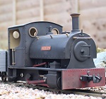
How would you go about something like this? I can't even think of where to start, even in Tinkercad
I have had success with your domes and flares. I can now print any dome I like with minimal changes, I can't thank you enough for that
How would you go about something like this? I can't even think of where to start, even in Tinkercad
I have had success with your domes and flares. I can now print any dome I like with minimal changes, I can't thank you enough for that
- Untitled.jpg (41.96 KiB) Viewed 5161 times
The buck stops here .......
Ditton Meadow Light Railway (DMLR)
Member of Peterborough and District Association
http://peterborough.16mm.org.uk/
Ditton Meadow Light Railway (DMLR)
Member of Peterborough and District Association
http://peterborough.16mm.org.uk/
-
metalmuncher
- Cleaner

- Posts: 95
- Joined: Sat Oct 20, 2012 4:15 pm
Re: Using OpenSCAD to produce drawings for 3D Printing
I've had a bit of a go a that one. Just three "orange segment" shapes stuck together.
Not quite perfectly proportioned, maybe a bit of unequal scaling of the shells would make it better. I also didn't bother making the shells thin, depending on print scale such thin structures might not be easily printable, but the thin wall could be added relatively easily.
Code: Select all
$fn=64;

module ShellShape(width, straightlen, angle){
    rotate([90,90+angle/2,0])
        rotate_extrude(angle=angle)
            translate([-straightlen,-0,0])
                union(){
                    translate([0,-width/2,0])
                        square([straightlen,width]);
                    difference(){
                        circle(d=width);
                        translate([0,-width/2,0])
                            square([width/2,width]);
                    }
                }
};

union(){
    cylinder(d=11, h=0.5);
    ShellShape(8  ,3  ,60);
    ShellShape(7.8,2.5,120);
    ShellShape(7.4,2  ,160);
}
- Attachments
-
- vent.PNG (38.97 KiB) Viewed 5147 times
Re: Using OpenSCAD to produce drawings for 3D Printing
Excellent! I'm still finding OpenSCAD fascinating, and enjoying the new uses it can be put to...
Oh wow, this is great. I just stared at Steve's pics and scratched my head.metalmuncher wrote: ↑Wed Jan 05, 2022 6:48 pmI've had a bit of a go a that one. Just three "orange segment" shapes stuck together.
Not quite perfectly proportioned, maybe a bit of unequal scaling of the shells would make it better. I also didn't bother making the shells thin, depending on print scale such thin structures might not be easily printable, but the thin wall could be added relatively easily.
One thing I noticed is that the pivot point in the shells is not at the absolute tip of the 'segments'. So I had a fiddle adding in bluntness factor. I don't think it's helped much, it's made it more complicated and made the model worse at the same time! I had to add in a factor to make sure it disproportionately affected the 'top' shell since 'blunting' the shells with very large angles doesn't make much sense. Having looked up Ash's Patent Carriage Ventilators (I wasn't familiar with them) it looks to me like it's necessary to model the inner shells in two parts, bringing them closer together along the x-axis to give that almost parabolic cross-section in the x-z plane. But I'm too tired to do any more fiddling tonight!

Code: Select all
topShellAngle = 50; // [20:5:80]
secondShellAngle = 110;  // [80:5:140]
thirdShellangle = 160;   // [140:5:180]
bluntness = 0; // [0:0.5:5]
// Decrements in the radius of each shell
redrad = 0.2; // [0.1:0.1:0.5]
angles = [topShellAngle,secondShellAngle,thirdShellangle,180];
module ShellShape(width, straightlen, angle, bluntness){
    pf=bluntness*pow((1-angle/180),2);
    difference() {
        translate([0,0,-pf])
            rotate([90,90+angle/2,0])
                rotate_extrude(angle=angle)
                    translate([-straightlen-pf,-0,0])
                        union(){
                            translate([0,-width/2,0])
                                square([straightlen+pf,width]);
                            difference(){
                                circle(d=width);
                                translate([0,-width/2,0])
                                    square([width/2,width]);
                            }
                        }
            translate([-straightlen-pf-width/2-1,-width/2-1,-pf])
                cube([2*(straightlen+pf)+width+2,width+2,pf]);
    }
};
union(){
    cylinder(d=11, h=0.5);
    for (i=[0:3]) {
        ShellShape(8-redrad*i,3-0.5*i,angles[i],bluntness);
    }
}

$fn=64;-
-steves-
- Administrator
- Posts: 2424
- Joined: Thu Jul 28, 2011 1:50 pm
- Location: Cambridge & Peterborough
Re: Using OpenSCAD to produce drawings for 3D Printing
OMG! 
How do you guys do this? I must admit I tried reading through the code to see how to make it bigger / smaller and I just don't have a clue, completely lost me on this one, but very well done
How do you guys do this? I must admit I tried reading through the code to see how to make it bigger / smaller and I just don't have a clue, completely lost me on this one, but very well done
The buck stops here .......
Ditton Meadow Light Railway (DMLR)
Member of Peterborough and District Association
http://peterborough.16mm.org.uk/
Ditton Meadow Light Railway (DMLR)
Member of Peterborough and District Association
http://peterborough.16mm.org.uk/

Re: Using OpenSCAD to produce drawings for 3D Printing
Glad it's not just me.
I think I could see how to do this in Sketchup. I'd have a go but I'm a bit tied up with the contractors loco atm.
Philip
Re: Using OpenSCAD to produce drawings for 3D Printing
Finally came back to the shell problem... It's a really interesting one - very tough, very instructive. I've a feeling I'm going to be coming back to it for years, chipping away at improving it with each new trick I learn in OpenSCAD. I certainly haven't cracked it yet, although managed to model each shell separately and pivot them all from a point some way from the origin around which they were extruded...

No idea how it will print, of course. Potentially some large overhangs, and the base I've added may make it difficult to remove the supports...
Code: Select all
// The width of the largest shell
maxWidth = 7; // [0:10]
// The side length of the longest shell
maxSideLength = 4; // [0:0.5:5]
// Angle described by each shell
shellAngle = 37; // [30:40]
// How far from the origin of the shells to the pivot point
pivotOffset = 2; // [0:0.5:4]
module ShellShape(width, straightlen, angle){
    rotate([90,90+angle/2,0])
        rotate_extrude(angle=angle)
            translate([-straightlen,-0,0])
                union(){
                    translate([0,-width/2,0])
                        square([straightlen,width]);
                    difference(){
                        circle(d=width);
                        translate([0,-width/2,0])
                            square([width/2,width]);
                    }
                }
};
baseThickness = 0.5;
shellOverlap = 1/3; //proportion of each shell to overlap
widthStepDown = 0.25; // how much to reduce the width by for each successive shell
sideLengthStepDown = 0.1; // how much to reduce the side length by for each successive shell
translate([0,0,pivotOffset/2+baseThickness])
    for(i=[0:1])
        mirror( [i, 0, 0] )
            difference() {
            union() {
                for (i=[0:3]) {
                    rotate([0,i*(1-shellOverlap)*shellAngle,0])
                        translate([0,0,-pivotOffset])
                            ShellShape(maxWidth-i*widthStepDown,maxSideLength-i*sideLengthStepDown,shellAngle);
                }
                translate([0,0,-pivotOffset])
                    cylinder(h=pivotOffset+2,d=maxWidth-4*widthStepDown);
                translate([0,0,-pivotOffset])
                    cylinder(h=1,d=maxWidth+3);
            }
            translate([-(maxWidth+maxSideLength+1),-(maxWidth+maxSideLength+1)/2,-(maxWidth+maxSideLength+1)/2])
                cube(maxWidth+maxSideLength+1);
            translate([-0.5,-(maxWidth+maxSideLength+1)/2,-(maxWidth+maxSideLength+1)-pivotOffset/2-baseThickness])
                cube(maxWidth+maxSideLength+1);
            }
$fn=100;Re: Using OpenSCAD to produce drawings for 3D Printing
I think it would print ok in resin but FDM would be difficult I suspect.
Philip
-
-steves-
- Administrator
- Posts: 2424
- Joined: Thu Jul 28, 2011 1:50 pm
- Location: Cambridge & Peterborough
Re: Using OpenSCAD to produce drawings for 3D Printing
What I can say is they print brilliantly in resin as I have already done some.
The picture shows the vents printed and supports broken off, but no cleaning up has been done. If anyone wants the torpedo vent stl file, just let me know. The shell vents were done in openscad using the code provided and tweaked for size, hence the 2 sizes.
I also printed a dome, it came out very well on the top circle it, but the flare was very bitty, but workable.
- IMG_20220113_092242.jpg (1.49 MiB) Viewed 5855 times
The buck stops here .......
Ditton Meadow Light Railway (DMLR)
Member of Peterborough and District Association
http://peterborough.16mm.org.uk/
Ditton Meadow Light Railway (DMLR)
Member of Peterborough and District Association
http://peterborough.16mm.org.uk/
Re: Using OpenSCAD to produce drawings for 3D Printing
Excellent! That's fast work - and they look great, better than I thought they'd turn out!
-
-steves-
- Administrator
- Posts: 2424
- Joined: Thu Jul 28, 2011 1:50 pm
- Location: Cambridge & Peterborough
Re: Using OpenSCAD to produce drawings for 3D Printing
I don't know if anyone has tried it, but Tinkercad also has a code type way of doing things called codeblocks.
This is a screenshot of an example one that I was playing around with.
This is a screenshot of an example one that I was playing around with.
- delete.JPG (241.83 KiB) Viewed 5856 times
The buck stops here .......
Ditton Meadow Light Railway (DMLR)
Member of Peterborough and District Association
http://peterborough.16mm.org.uk/
Ditton Meadow Light Railway (DMLR)
Member of Peterborough and District Association
http://peterborough.16mm.org.uk/
Re: Using OpenSCAD to produce drawings for 3D Printing
Didn't even know about that - that looks really useful, especially given how easy it is to quickly get something together in TinkerCAD, and it looks like this could enable progression to quite precise refinements.
Re: Using OpenSCAD to produce drawings for 3D Printing
Well done to both of you as a collaborative effort. The prints have turned out pretty much as I thought they would.
Philip
-
-steves-
- Administrator
- Posts: 2424
- Joined: Thu Jul 28, 2011 1:50 pm
- Location: Cambridge & Peterborough
Re: Using OpenSCAD to produce drawings for 3D Printing
This is an example of CodeBlocks working. It has differing speeds, I went from medium to fast after a couple of runs through.
The buck stops here .......
Ditton Meadow Light Railway (DMLR)
Member of Peterborough and District Association
http://peterborough.16mm.org.uk/
Ditton Meadow Light Railway (DMLR)
Member of Peterborough and District Association
http://peterborough.16mm.org.uk/
Re: Using OpenSCAD to produce drawings for 3D Printing
I meant to update this thread with progress on my headboard, but forgot to do so. I'd got to the point where I could generate a headboard but the letter spacing was causing me a headache:
The library is fontmetrics which includes the function measureText() which returns the width of a string - exactly what I needed! So I can now measure the width of each letter individually and use that to work out the angle to move through before position the next letter. Job done!
But that code won't work yet, because the function measureText() isn't defined in my project, it's in fontmetrics.scad. So first of all I need to download fontmetrics (and its companion fontmetricsdata.scad) and I can then either place it in the same directory (folder) as my project, or in one of the places OpenSCAD looks for libraries - I won't cover the details of that here because it depends which operating system you're on, but it's an option if you think that's neater. Once I've done that, I have to include a line in my project to reference fontmetrics. There are actually two OpenSCAD commands that can do this: include<> and use<>. If you include<file.scad>; it basically pulls in everything in file.scad as if it were in your file. But if you use<file.scad>; it only brings in the modules and functions from file.scad so you can call them from with your project. I prefer this: it means if I define a constant in my project that happens to share the same name as a constant in the file I want to reference, it won't cause a clash.
Anyway, having added fontmetrics.scad to the same folder as headboard.scad, all I need to do now is add this line:
Now my function above will be able to use measureText().
The benefit of this command is that I can now break down my projects into multiple files. So if I were drawing a wagon I could, say, have files axlebox.scad and solebar.scad and coupling.scad etc. and then in reference them in wagon.scad with 'use<axlebox.scad>;' etc. Not only will this make it more organised to work on and easier to find the bits of code I'm looking for, but potentially I can reuse bits (for example I might want to use 'axlebox.scad' in 'van.scad'). Admittedly this also increases the potential for complexity... and this has made me think about versioning. I'm experimenting with using GitHub for this - so you can now find the latest working headboard files on GitHub.
I've also finally got round to putting the headboard project on Thingiverse.
So even if you don't want to play with the OpenSCAD code you can now download it and type your own headboard text in as a parameter to generate an STL file for any headboard you like.
Well, I found the library to do this, and in the process I also found a new OpenSCAD command which I think is going to be really useful for structuring projects.SimonWood wrote: ↑Sat Jan 01, 2022 9:14 am Even after fiddling the parameters you can see the letter spacing is a problem more generally - since really having each letter spaced evenly never works. An 'I' is much narrower than a 'W'. I haven't found anything in OpenSCAD to solve this, although I think from Googling around there may be libraries other people have developed which I can use - I need to look into this more...
The library is fontmetrics which includes the function measureText() which returns the width of a string - exactly what I needed! So I can now measure the width of each letter individually and use that to work out the angle to move through before position the next letter. Job done!
Code: Select all
function angle_subtended_by_arc(radius,arc_length) = arc_length*360/(2*radius*PI);
function add_elements(array, to=-1, from=0) = from < len(array) - 1 && (from < to || to == -1) ? array[from] + add_elements(array, to, from + 1) : array[from];
function angles_of_letters(the_text,radius,font_size) = [for (i=[0:len(the_text)-1]) angle_subtended_by_arc(radius,measureText(the_text[i],size=font_size))];
module text_arc(the_text,radius,font_size,center=false) {
    angles_of_letters=angles_of_letters(the_text,radius,font_size);
    center_offset = center ? add_elements(angles_of_letters,len(the_text)-1)/2 : 0;
        for (i = [0:len(the_text)-1]) {
            rotate(i == 0 ? center_offset : center_offset-add_elements(angles_of_letters,i-1))
                translate([0,radius,0])
                    text(the_text[i],halign="left",font_size);
    }

}
Anyway, having added fontmetrics.scad to the same folder as headboard.scad, all I need to do now is add this line:
Code: Select all
use <fontmetrics.scad>;The benefit of this command is that I can now break down my projects into multiple files. So if I were drawing a wagon I could, say, have files axlebox.scad and solebar.scad and coupling.scad etc. and then in reference them in wagon.scad with 'use<axlebox.scad>;' etc. Not only will this make it more organised to work on and easier to find the bits of code I'm looking for, but potentially I can reuse bits (for example I might want to use 'axlebox.scad' in 'van.scad'). Admittedly this also increases the potential for complexity... and this has made me think about versioning. I'm experimenting with using GitHub for this - so you can now find the latest working headboard files on GitHub.
I've also finally got round to putting the headboard project on Thingiverse.
So even if you don't want to play with the OpenSCAD code you can now download it and type your own headboard text in as a parameter to generate an STL file for any headboard you like.

Re: Using OpenSCAD to produce drawings for 3D Printing
Fascinating stuff, but how the heck do you print those domes and vents on a filament printer. I have a Flashforge AD3 and I use Tinkercad. The Codeblocks looks interesting though. Is it easy enough to use Steve.
The OpenSCAD is way beyond me though...
The OpenSCAD is way beyond me though...
ROD
Life is so easy when I run my trains.


https://gardenrails.org/forum/viewtopic ... 41&t=11364
https://www.youtube.com/@fairywoodlightrailway
Life is so easy when I run my trains.


https://gardenrails.org/forum/viewtopic ... 41&t=11364
https://www.youtube.com/@fairywoodlightrailway
Who is online
Users browsing this forum: No registered users and 4 guests