The Charnwood Forest Light Railway

A place for the discussion of garden railways and any garden style/scale portable and/or indoor layouts
User avatar
ge_rik
Administrator
Administrator
Posts: 6477
Joined: Sun Oct 25, 2009 10:20 pm
Location: Cheshire
Contact:

Re: The Charnwood Forest Light Railway

Post by ge_rik » Tue Jan 05, 2021 9:18 am

Andrew wrote: Mon Jan 04, 2021 6:16 pm The cat thinking you'd lost the plot reminded me that I was praying the neighbours weren't watching the other day as I bashed up coal on the front drive. They' really think we'd fallen on hard times if the saw me scrabbling about after lumps of coal just a few mm across...
:laughing3: :laughing3: :thumbright:

Rik
------------------------
Peckforton Light Railway - Blog Facebook Youtube

User avatar
Soar Valley Light
Driver
Driver
Posts: 1451
Joined: Sun Dec 08, 2013 5:18 pm
Location: North West Leicestershire

Re: The Charnwood Forest Light Railway

Post by Soar Valley Light » Sun Jan 10, 2021 4:22 pm

Hello Readers,

I mentioned my 'wandering' track alignment in my New Year post, I have an update.

One advantage of having the railway is that the garden is much lower maintenance, thanks to plenty of ground cover plants and a reduction in 'crop' plants. Most of the growing is done on the allotment these days but I still have a few fruit bushes and a row of raspberries. The raspberries are old now and and some of the canes died off last year, however, there are plenty of healthy roots pushing out from the canes, some came up very close to the railway and needed moving to avoid some incongruously giant foliage beside the track. This afternoon seemed like a good opportunity so I set too and removed the strays to the proper run of canes. This job took me into places I don't often get and thus gave views along the railway I don't normally see. To my horror the alignment problems mentioned are, in places, far worse than I thought. In fact, the kinks are so severe that I'm pretty sure they are bad enough to fetch anything I ran at the moment off the road. I can't pin-point the cause but the problems all see to exist where the maximum amount of 'terra forming' took place to create the railway. I thought I'd thoroughly compacted the ground as it went back in, ramming it with a punner in thin layers, but nevertheless it can only be ground movement which has done this. Many of the 'kinks' are outward, so if it was thermal movement of the track it would need hot weather to cause it - this has been noticeably absent in North West Leicestershire of late! No matter what the cause, I can see no option but to unpin the track and ease out the alignment to something trains can run over smoothly. If it happens again I'm going to seriously consider reconstructing the formation. That would be a nightmare but better than having this palaver every year!

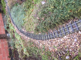
This may not look bad but it's far worse than the alignment I originally layed.
2021 track misalignment1.JPG
2021 track misalignment1.JPG (63.51 KiB) Viewed 5389 times
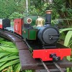
This curve is on an embankment between 6" and 12" high on about 2' of filled ground (I was mining sand and gravel from a natural deposit I found!) It was a really sweet, regular curve when layed and has survived for several years without movement.
2021 track misalignment4.JPG
2021 track misalignment4.JPG (63.47 KiB) Viewed 5389 times
This turnout was built and layed as a straight turnout, it's developed a distinct curve over the last 18 months, the mainline is actually the curved leg and the regular curve that was laid now has 'lumps' in it! There was almost no filling of the ground in this area.
2021 track misalignment5.JPG
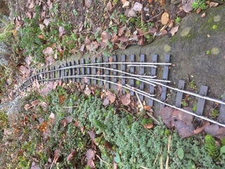
2021 track misalignment5.JPG (61.3 KiB) Viewed 5389 times
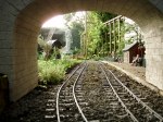
The next two photo's are on an even higher embankment than the one previously mentioned, just over 12" of fill and right on the edge of the sunken path. The ground is supported on concrete troughing units laid on their sides on top of each other. I expected this might move as compacting soil into the open troughs wasn't easy. There was some movement two years ago but I adjusted the alignment last year. This is also the stretch I ballast up in ash, held with building glue. It's not a soild bond as there is little other than the Terram under the track for it to bond to but it seems to have held last year (I'm hoping these aren't 'famous last words'!).
2021 track misalignment6.JPG
2021 track misalignment6.JPG (61.61 KiB) Viewed 5389 times
2021 track misalignment7.JPG
2021 track misalignment7.JPG (58.25 KiB) Viewed 5389 times
The next shot is of the loop point at the end of the first embankment mentioned. They were part of the regular curve when laid. The final shot is of the loop at Woodhouse, immediately behind the points, the loops were laid with regular curves and with a constant interval between them, as you can see, that is no longer the case. The cross level has also gone way off here too. I didn't get the bubble out to check - I didn't need to!

It's all very frustrating but, as the old saying goes, 'if at first you don't succeed try, try again' (but after the second try, do something different!)

SVLR Andrew
Attachments
2021 track mislaignment2.JPG
2021 track mislaignment2.JPG (62.1 KiB) Viewed 5389 times
2021 track misalignment3.JPG
2021 track misalignment3.JPG (60.78 KiB) Viewed 5389 times
Last edited by Soar Valley Light on Wed Feb 03, 2021 7:27 pm, edited 1 time in total.
"Smith! Why do you only come to work four days a week?
"'cause I can't manage on three gaffer!"

User avatar
philipy
Moderator
Moderator
Posts: 5000
Joined: Sun Jan 30, 2011 3:00 pm
Location: South Northants

Re: The Charnwood Forest Light Railway

Post by philipy » Sun Jan 10, 2021 6:18 pm

Andrew,
That all doesn't look good at all. Forgive me but I can't remember if/how your track is fixed down?
Philip

User avatar
Soar Valley Light
Driver
Driver
Posts: 1451
Joined: Sun Dec 08, 2013 5:18 pm
Location: North West Leicestershire

Re: The Charnwood Forest Light Railway

Post by Soar Valley Light » Sun Jan 10, 2021 7:03 pm

Hi Philip,

It's not good at all.

The foundation is two 2x1 Filcriss strips spaced apart with 2x2 Filcriss blocks alternating with 2x2x18 to 24" Filcriss posts at 18" centres. The space between the Filcriss strips is filled with pea gravel before being covered in Terram (off cuts from the real thing picked up at work), the ground is made up around the filcriss and well rammed to support it. The track is layed on top of this, tacked into the Filcriss around every six sleepers (but up to every other sleeper on curves). The pinning seems to be holding so it's the Filcriss that's moving in the ground. It occurs to me that frost heave may be a factor but there is one short spot (not pictured) between two turnouts where the Filcriss is stiffly braced and well supported by the ground where there is a misalignment normally associated with the worst of the hot weather. I'm really at a loss to explain it. It defies everything I've ever learnt about managing track - and I do that for a living!

SVLR Andrew
Last edited by Soar Valley Light on Wed Feb 03, 2021 7:27 pm, edited 1 time in total.
"Smith! Why do you only come to work four days a week?
"'cause I can't manage on three gaffer!"

User avatar
philipy
Moderator
Moderator
Posts: 5000
Joined: Sun Jan 30, 2011 3:00 pm
Location: South Northants

Re: The Charnwood Forest Light Railway

Post by philipy » Sun Jan 10, 2021 9:16 pm

It's surprising how much stuff moves around, however well tamped, once water gets involved. I suspect that because your Filcris is a rigid construction ( Without expansion gaps, presumably?), once one section moves, it puts undesigned strains on everything else, and that then continues to "wriggle" as it tries to regain its built-in angles and curves every time it rains, dries or freezes.
Philip

User avatar
Peter Butler
Driver
Driver
Posts: 5217
Joined: Sun Sep 09, 2012 10:33 pm
Location: West Wales

Re: The Charnwood Forest Light Railway

Post by Peter Butler » Sun Jan 10, 2021 9:23 pm

philipy wrote: Sun Jan 10, 2021 9:16 pm It's surprising how much stuff moves around, however well tamped, once water gets involved. I suspect that because your Filcris is a rigid construction ( Without expansion gaps, presumably?), once one section moves, it puts undesigned strains on everything else, and that then continues to "wriggle" as it tries to regain its built-in angles and curves every time it rains, dries or freezes.
If so, could that be described as 'not fit for purpose?' I thought Filcris was manufactured and promoted for this job.
The best things in life are free.... so why am I doing this?

User avatar
pippindoo
Trainee Fireman
Trainee Fireman
Posts: 144
Joined: Sun Nov 14, 2010 9:01 pm
Location: Leeds
Contact:

Re: The Charnwood Forest Light Railway

Post by pippindoo » Mon Jan 11, 2021 4:54 am

As a Filcris advocate, Ive learned its a very easy to use product, quick to erect, easy to cut, screw together and one big advantage is its flexibility. Ive noticed this numerous times on my railway when on a hot day, the whole frame can move outwards slightly as it expands, though ive never had anything even remotely like Andrew is experiencing. However, my system is approximately 15" high off the ground and so the legs supporting it have a bit of leeway to allow this flexibility, and the resultant resettling as temperatures change. The whole raised frame can, and does , adjust as one, and the flexibility of the supporting legs have the ability to bend slightly to allow it without any problems. I remember Andrew, when you posted photos as you started to bury your railways framework into the earth and thinking then that, being buried like that, if it was still prone to the expansion and contraction phenomanon, it could get 'messy'. As youve posted above too, your trackwork is very securely fastened to the framework, almost every other sleeper at some points, I cant help thinking that with any movement, however slight, wether expansion, contraction or frost heave, there just isnt much 'give'. Obviously, a concrete or block foundation isnt as prone to expanding and contracting. Just a suggestion based on my experience. It must be gutting to have such a distaster and i sincerely hope it isnt too much graft to put it right and crack on. It would be interesting to hear anyone elses experience of a 'buried' Filcris framework. I guess lots have used Filcris to edge lawns and flowerbeds but in that application its not really critical if it warps slightly now and then. Hmmm, I'm intrigued!

User avatar
Soar Valley Light
Driver
Driver
Posts: 1451
Joined: Sun Dec 08, 2013 5:18 pm
Location: North West Leicestershire

Re: The Charnwood Forest Light Railway

Post by Soar Valley Light » Tue Jan 12, 2021 6:59 pm

Hello Pipp,

Like you I've been a great advocate of Filcriss. As you say, flexible, easy to use, not to mention quick to assemble and easy on the eye without further work.

I think you have probably hit the nail on the head here, it's the fact that it's buried - the very thing which I imagined would make it stable and resistant to heat variations. I was concerned about hot weather but that doesn't seem to affect it, I never dreamt that the cold would pull it about or that the frost would push it about. The fact that the movement doesn't happen every year gives me a wee bit of hope. I think it's worth unfastening everything and correcting the alignment. It seems to have worked for the ballasted section (so far!). Maybe I should get some ballast around the problem area as soon as it's been lined up again.

If that fails I can see no option but to go for complete reconstruction. That will be a disaster, the primary problem is that I can't afford it. I'm not sure I could face digging the garden up again (I'm not sure I'd be allowed to). I have everything crossed for success with the realignment! I shan't rush into it though, the weather needs to be a bit better before I make a start.

SVLR Andrew
Last edited by Soar Valley Light on Wed Feb 03, 2021 7:27 pm, edited 1 time in total.
"Smith! Why do you only come to work four days a week?
"'cause I can't manage on three gaffer!"

User avatar
ge_rik
Administrator
Administrator
Posts: 6477
Joined: Sun Oct 25, 2009 10:20 pm
Location: Cheshire
Contact:

Re: The Charnwood Forest Light Railway

Post by ge_rik » Wed Jan 13, 2021 11:19 am

I've not used Filcris but I have experienced settling with the concrete 'breeze' blocks I use. I can't help feeling that movement is somewhat inevitable with any sort of track foundation given that we are wanting fairly fine tolerances in a relatively hostile environment.

Not sure if this would work, but I can't help thinking that maybe you could reduce the number of fixing points between your track and the Filcris foundations??? That way, the track would be able to 'give' a bit more when the foundations move. Doesn't real track sort of float above the trackbed? Would this in some way mirror real practice?

Just a thought.

Rik
------------------------
Peckforton Light Railway - Blog Facebook Youtube

User avatar
Jimmyb
Fireman
Fireman
Posts: 492
Joined: Sat Nov 23, 2019 10:43 pm
Location: Weston-super-Mare

Re: The Charnwood Forest Light Railway

Post by Jimmyb » Wed Jan 13, 2021 2:17 pm

My current railway in on trenches and blocks for elevated areas, and my initial plan was to screw the track down ever 30 - 60 cm, using standard fish-plates to hold the track down. My first summer (2018) saw some tremendous movement, and I now (generally) use a more substantial method of semi-permanently holding the track together, and allow on the whole the track to move over the ballast, except where specific positioning is required. The track moves, but as a whole, and disinformation in the track has not (yet) occurred.

User avatar
Soar Valley Light
Driver
Driver
Posts: 1451
Joined: Sun Dec 08, 2013 5:18 pm
Location: North West Leicestershire

Re: The Charnwood Forest Light Railway

Post by Soar Valley Light » Fri Jan 15, 2021 8:38 pm

Thanks for sharing your views guys, your suggestions are all worthy of further study and considering. I need some better weather before I can put any of it to practical purpose. I shall update you once the temperatures rise! :sunny:

In other news I have made a start on my momentum van. I began by stripping down the Zeecar mechanism. That was more of a challenge than I expected because I've only got a very small vice and there wasn't really room to position the mechanism between the jaws. I found centre punching the axles out from the wheels most successful. At this point I thought the axles were off centre on the mechanism body but on reflexion I now wonder if punching the wheels off may have shifted it even further. The picture clearly shows (on the uncut axle) that they were off centre. It was clear that the body is quite flimsy and the axles are, indeed, free to move laterally by a small amount. Care, in fact great care is needed. The CFLR is a 1'-11 1/2"gauge railway and so I run on 32mm track, my Zeecar axles were about 10mm longer than the IP engineering wheelset axles and so needed cutting down. With the wheels off I did manage to grip them in the vice. When I had finished I fancied I might have kinked the axle slightly, it had certainly shifted in the bearing again but once adjusted looked ok. The IP wheels were easy to 'de-axle'. They were an easy fit on the Zeecar axles, possibly a little too easy. The photo below shows the trimmed axles and the stripped down IP wheelsets.
Momentum - zeecar dismantled.JPG
Momentum - zeecar dismantled.JPG (36.36 KiB) Viewed 5057 times

On fitting the wheels to the Zeecar axles I detected a slight looseness but convinced myself that it would be ok once there was some glue on the axle. When trimmed for 32mm use there isn't a lot of axle poking out of the mechanism, great care is needed to make sure the wheel doesn't carry any glue back along the axle as far as the body. When positioning the wheels to make sure everything is equally spaced around the centre of the body there was a certain amount of shuffling of the wheels, double so when I realised there was still a very slight looseness, enough to risk a 'wobble'. Whilst juggling all these aspects of positioning I realised that glue had migrated a long way towards the body. I gave it a scrape with a blade and thought I'd got away with it. I now left well alone for 12 hours until the two part epoxy had properly hardened.

After an impatient wait my first concern was to see if there was any 'wobble' of the wheels on the axles. I gripped the body and a wheel with a view to 'giving it a spin', to my horror nothing moved, the glue had caught the axle in the body! I ran the blade around the axle where it entered the body and gave the axle a gentle tap and to my relief movement returned! My joy was short lived as both wheels were out of true, the one on the end of the axle I suspected may have been bent was about 3mm out, the other about half that. Clearly this would not do. Some gentle manipulation with pliers had no effect. Leaning back on all my permanent way experience, I picked up a hammer! it was only a small tack hammer and (for a pway man) I wielded it very gently. Some carefully aimed taps to the outer side of the wheel rims followed. This really was a case of 'slowly, slowly, catchy monkey'. Taking it a little bit at a time I managed to get things back into true. I'm satisfied there is no more than 0.25mm of wobble on either wheel now. As the axle also still runs pretty true I am more inclined to think that there was some deformation of the axle during the shortening process and that the movement of the wheels on the axle was a very minor component of the problem.

I had toyed with the idea of mounting the mech on the van floor with a chain drive to the IP wheelset, however, when I looked at the van assembly it looked feasible to use the Zeecar axle so I thought I'd give it a try. A hole was cut in the floor to accept the mechanism before construction started. The build of the body has been progressing all week. My kit building experience in this scale is virtually non existent, this is only my second one. I'm 90% of the way through building a Brandbright hopper wagon. I was thoroughly impressed with this kit, the standard of the components, the clarity of the instructions and the way the kit went together. I like my vans and coaches to be as tall as my (Accucraft) locos so I am always looking for the taller items of rolling stock. The Brandbright brake van looked good but the IP version had an extra 10mm of height so I went with that. It's a nice kit. Subtly different in all aspects mentioned to the Brandbright kit. I fancy there might be slightly less detail but without comparing the two it can be no more than a gut feeling. I may see if I can persuade someone to buy me a Brandbright van for my birthday to have a go with. I certainly want a second momentum van so this may be the second project. I'd like to try a floor mounted, chain driven version of the Zeecar mech and I also have a smaller and slightly less resistant mech out of a Glendale Express toy that I'd like to try - all in good time though! The final body assembly stage of the IP van is sitting on the bench gluing as I type. I'm hoping I might get down to the actual installation of the 'momentum' into the 'van' over the weekend. I'll keep you all posted of course.

SVLR Andrew
Last edited by Soar Valley Light on Wed Feb 03, 2021 7:28 pm, edited 1 time in total.
"Smith! Why do you only come to work four days a week?
"'cause I can't manage on three gaffer!"

User avatar
Soar Valley Light
Driver
Driver
Posts: 1451
Joined: Sun Dec 08, 2013 5:18 pm
Location: North West Leicestershire

Re: The Charnwood Forest Light Railway

Post by Soar Valley Light » Sat Jan 23, 2021 12:15 pm

Hello dear readers.
I seem to have to re-learn some lessons over and over again. I’ve just spent the better part of an hour composing a post, only for it to vanish into the ether again when I came to post it! Only then did I remember that when writing a post, particularly longer posts or ones that will be written with interruptions, the safest way is to write them in Word and copy and paste into the post when ready. Hey ho!

So, what was I banging on about? Well, progress on the momentum van has continued this week, albeit at, well ….. momentum van pace (Sorry!). I assembled the mechanism into the van with the ‘driven’ axles running in the axle boxes on the van. The ‘idle’ axle was mounted above van floor level using scrap plywood fret for brackets. Two of the photos in this post illustrate this. I was quite pleased with this arrangement – right up to the point where I gave it a try. I achieved motion in one direction but in the other there was a tight spot in the rotation of the ‘drive’ axle that stopped the mechanism dead, resulting in the wheels just skating along the rail head. Even 4½lb of steel didn’t provide enough traction to overcome the ‘bind’. I can only presume from this that I did manage to put a kink in the axle during the dismantling process of the original mechanism. I’m surprised by this as, for me, I was being particularly careful. I managed to spring the W irons out far enough to expose the axle stubs and set to with a file to reduce their diameter, the theory being that, with some play between the axle and the bearing, any ‘wobble’ in the axle should be able to occur without binding (but hopefully without the van ‘wagging it’s tail’ like an over excited puppy!). This took several goes but eventually satisfactorily smooth motion seemed to be achieved in both directions, I’ve also added a dab of copper grease in the axle bearings to aid future revolutions. How successful this has all been will only become clear with time. The next step is to road test the thing, but the weather here today is hardly conducive to that (it’s snowing!) so will have to wait for another day. The build has convinced me enough to want to have a second go, this time with the mechanism mounted on the van floor and driving onto the vans own axle using a chain drive. I’m already on the lookout for a Zeecar mechanism at the right price.

Merged_document.jpg
Merged_document.jpg (51.07 KiB) Viewed 4950 times
The third photo in this post is of the crossing nose on the turnout that came off the works assembly line this week. All my turnouts are built using Cliff Barker components, so I start with some lengths of rail, some plastic ‘timbering’ and a pile of chairs. Cliff’s chairs are designed for Gauge 1 turnouts, they are a pretty good match in size for 16mm chairs but the ‘common’ or S1 chairs I find a little small, so I use what Cliff markets as ‘Bridge’ chairs for my commons. These are accurate representations of a prototype L1 chair, used mainly in turnouts where clearances prevent the use of S1’s. (There is an even smaller M1 chair for similar purposes – both L1’s and M1’s are also used on ‘Way Beam’ bridges, hence the term ‘bridge chair’). Even with these reduced footprint chairs, the prototype still requires the use of ‘special’ chairs in the tightest locations. These are very specifically manufactured for locations on particular angle crossings or particular sized switches (also angle related). These locations are the ‘tricky’ areas for building turnouts in the way I do – fortunately, for my standard 8’ loose heeled switch turnouts with a 1 in 6 crossing nose there are only three such specials (if you discount the switch heel ‘hinge’ assembly). Getting these right in the crossing nose is particularly important as they also partially hold the vee and the wing rails together (although in the prototype bolted blocks form the main assembly connections). Over my various builds (this is turnout 11) I have tried various methods, some have been retained some have been ditched. Most recently I’ve been trying to improve the manufacture of the point and splice rails which form the vee. I file these up from plain rail, I’m no machinist or mechanical engineer, so forming these is one of my weaker areas of expertise. The greater area of experimentation has been in the means of assembling the vee and the wing rails. My early attempts attempted to araldite spacing blocks between the wings and vee then, once firmly held, using cut down slide chairs to support them and hold the complete assembly in place. The blocks were necessarily small and fiddly, so achieving an accurate and consistent size and shape was not easy. The flangeway dimension is critically important and there also needs to be sufficient clearance for the flange above the block. These factors made the procedure time consuming, fiddly and at risk of disastrous inaccuracies. More recent builds began to experiment with the use of ‘cut and pasted’ chairs to form the gap. This latest version uses cut down check chairs in both the A and B positions (crossing nose and first after the crossing nose) and appears to have been the most successful yet. Time will tell how this arrangement stands up to life in the great outdoors! For the time being the CFLR engineer is satisfied with the result.
Once the weather improves enough to get out for a test run (probably about June!) I’ll update you all on how I get on with the van.

SVLR Andrew
"Smith! Why do you only come to work four days a week?
"'cause I can't manage on three gaffer!"

User avatar
Soar Valley Light
Driver
Driver
Posts: 1451
Joined: Sun Dec 08, 2013 5:18 pm
Location: North West Leicestershire

Re: The Charnwood Forest Light Railway

Post by Soar Valley Light » Wed Feb 03, 2021 9:33 pm

Greetings dear readers,
Having picked up a new loco just over a week ago I was very keen to give her a try. It was something I've been after for ages, the final one of the pair that will be the CFLR's loco fleet. I'm now working on an excuse to keep by rebodied Edrig (complete with tender) and Excelsior, both of which are beautiful loco's. My line is starting to have more than one parallel with the Cambleton & Machrihanish - and I'm not sure whether that's a good thing or not! There would have been no good reason for the CFLR to have more than two locos but I suppose they may have picked up a quarry loco or two.... but I digress (how unlike me!)

The first problem with having a run was whether the road was in a fit state to run on (a sad dilemma for a permanent way man!). Some brutal 'shuffling' of the worst sections of misalignment eased most of the problems. I had to set to with some pruning equipment and beat the undergrowth back but having done all this I decided it was worth a try. All this was very much a spur of the moment decision with a spare hour I had on Sunday when the weather took a turn for the better. By the time I'd complete my preparations it was spotting with rain again but nothing was going to deter me now! I was pleased with the loco, although the valve setting on the reverser seemed slightly out. I had the momentum van rigged up with a temporarily fitted coupling so I decided to give it a go. On the last light engine run back to collect the van the loco stopped responding to the R/C. Of course, not having planned the run I hadn't charged the loco up! I tried a couple of trips in manual but that seemed to be the end of reverse gear. I decided there was just enough steam left to give the momentum van a try so I hooked the engine on but as I did so the gas ran out! The bad luck continued as the clouds thickened and the rain began to fall, so I was officially put off a further steaming and retired indoors to seek for a solution in my best mates rhubarb vodka!

My permanent way had performed reasonably well under the light engine running. There was one spot where she persistently ventured onto Olde England but a little bit of extra ‘manipulation’ seemed to cure the problem. Whilst recognising that a light engine is far better at getting across the ‘lumps’ than a complete train, I was encouraged that the problems I’d spotted after the Winter may yet be redeemable. The wetter parts of Sunday had seen me sorting the chaos that passes for a cellar in our house. My workbench (such as it is) is down there too and I was running out of elbow room, so a sort out was inevitable. During my rummaging I came across a couple of vans I’d picked up amongst some other bits but which I never really intended keeping. The sun came out briefly on Monday so I dashed outside with them to get a couple of photo’s with which to advertise them for sale. The best spot for this was on the ballasted section of track which has remained stable since the ballasting work was completed. In the process of rolling them up and down to get the pictures I discovered a massive twist fault had developed. Correcting this would mean clearing away all the glued ballast to shim up under the sleepers. Some further investigations a little further along revealed that the ground had heaved substantially under one side of the loop points causing further significant twist problems. I’m coming to the conclusion that I’m left with little option but to go for full on reconstruction. If this ends up being the case I’m wondering whether to start completely from scratch or try and re-use those sections which have remained stable throughout this sorry story. I’m talking about maybe a third of the track that might be safe enough to leave. Once the weather is a little better I think a much closer study is required – and then it will be make your mind up time for yours truly!

SVLR Andrew
"Smith! Why do you only come to work four days a week?
"'cause I can't manage on three gaffer!"

User avatar
ge_rik
Administrator
Administrator
Posts: 6477
Joined: Sun Oct 25, 2009 10:20 pm
Location: Cheshire
Contact:

Re: The Charnwood Forest Light Railway

Post by ge_rik » Thu Feb 04, 2021 10:35 am

That is sad news, Andrew. Particularly after the meticulous care you put into constructing the trackbed in the first case. Perhaps the consolation is that we all learn from experience and you've certainly gained more than the average modeller in using Filcris.

Let's hope all you need to do is relay just a few sections....

Rik
------------------------
Peckforton Light Railway - Blog Facebook Youtube

User avatar
philipy
Moderator
Moderator
Posts: 5000
Joined: Sun Jan 30, 2011 3:00 pm
Location: South Northants

Re: The Charnwood Forest Light Railway

Post by philipy » Thu Feb 04, 2021 11:07 am

ge_rik wrote: Thu Feb 04, 2021 10:35 am That is sad news, Andrew. ....

Let's hope all you need to do is relay just a few sections....
Rik has put it perfectly. We'll all keep our fingers crossed, I'm sure.

I can't help wondering if your amazingly protoypical construction methods aren't inadvertantly part of the problem, though. An inch or so movement in the real world won't even notice and yet as you've found out the hard way, its more akin to the San Andreas Fault slipping in our world. I suspect that in the end you may have to join the rest of us and to accept a trackbed that isn't billiard table flat with calculatedly smooth curves, unfortunately.
Philip

User avatar
Peter Butler
Driver
Driver
Posts: 5217
Joined: Sun Sep 09, 2012 10:33 pm
Location: West Wales

Re: The Charnwood Forest Light Railway

Post by Peter Butler » Thu Feb 04, 2021 11:34 am

I do agree, after putting in so much time and effort this the worst possible scenario. I know you will overcome the problem and have a superior final result. We will be watching and learning as you go.
The best things in life are free.... so why am I doing this?

User avatar
Soar Valley Light
Driver
Driver
Posts: 1451
Joined: Sun Dec 08, 2013 5:18 pm
Location: North West Leicestershire

Re: The Charnwood Forest Light Railway

Post by Soar Valley Light » Thu Feb 04, 2021 7:23 pm

Thanks for the commiserations chaps. You know what they say, 'a trouble shared is a trouble halved'. I think my problem is a combination of things, including those you have mentioned. I don't think I fully understood the properties of the materials I was using either and they weren't widely tested in the way I used them. There is definitely a lesson to be learnt there.

Philips point about accepting imperfections is perfectly correct. My aim for precision in the first place was to allow these to creep in and I can see that they would be manageable on a firm road bed. To put some perspective on this, in 'real numbers' terms we would stop the road at work for a 1 in 90 twist fault and that's with rolling stock that has well maintained suspension. Far less severe twist faults can fetch you off the road though, as any number of RAIB reports will clearly demonstrate, although there is usually a secondary cause - often poor loading, faulty suspension, or both. For this reason we get quite excited at work about anything over 1 in 200 when it comes to twist. At the size of infrastructure we are dealing with in 16mm scale 1mm in 200mm must be very common but even 1 in 90 is so small it would be hard to measure - and almost all our stock is completely lacking suspension of any sort. It's quite amazing what we manage to get over with our little trains.

I'm doing nothing in a rush - if for no better reason that the weather is rubbish! I'm going to do a lot more studying of the problem and read up on possible solutions, I've already re-read Rik's description of road bed construction. One possibility I am considering is leaving the Filcris in place but excavating around is as neatly as I can to a depth of - say - 4" and then pouring concrete around it to a width of 4 - 6" to form a solid 'ground beam'. Thinking about it that might even be possible with the track in place, it would certainly be less disruptive to the plants which are really establishing themselves now. It may be worth at least a test section. I'd be interested in peoples thoughts on that one.

On the positive side it is giving me the opportunity to consider whether any improvements could be made to the track layout or the alignment. I haven't got much room to play with but there might be one or two possibilities. I certainly might be able to include some sort of stream that I've longed for ever since Rik and Philip planted the seeds of temptation in my mind! It might also give me the opportunity to replace one or two of the older turnouts, they've hardly been used but my latest developments in construction technique give a better result at the most critical of locations in the track (the crossing nose) .

Right, I'm off to put my thinking cap on. A little 'thought lubrication' may be in order. Now, where did I put that rhubarb vodka! :drunken:

SVLR ANdrew
"Smith! Why do you only come to work four days a week?
"'cause I can't manage on three gaffer!"

User avatar
philipy
Moderator
Moderator
Posts: 5000
Joined: Sun Jan 30, 2011 3:00 pm
Location: South Northants

Re: The Charnwood Forest Light Railway

Post by philipy » Thu Feb 04, 2021 8:32 pm

Soar Valley Light wrote: Thu Feb 04, 2021 7:23 pm At the size of infrastructure we are dealing with in 16mm scale 1mm in 200mm must be very common but even 1 in 90 is so small it would be hard to measure - and almost all our stock is completely lacking suspension of any sort. It's quite amazing what we manage to get over with our little trains.
The thing to factor in is this regard is our waaay overscale flanges, which mop up a multitude of sins. There is one section of Rik's line which shows up occasionally in his video's and every time I see it it amazes me how stuff seems quite happy to dip and twist and rock 'n roll through it. ( Sorry Rik!)
Soar Valley Light wrote: Thu Feb 04, 2021 7:23 pm One possibility I am considering is leaving the Filcris in place but excavating around is as neatly as I can to a depth of - say - 4" and then pouring concrete around it to a width of 4 - 6" to form a solid 'ground beam'. Thinking about it that might even be possible with the track in place, it would certainly be less disruptive to the plants which are really establishing themselves now. It may be worth at least a test section. I'd be interested in peoples thoughts on that one.
All I can say from my own bitter experience is to put some rebar in if you adopt this approach, particularly if you have to pour it in discrete sections. My clay has cracked a similar construction in at least three places, two of which were at joints with no cross-joint reinforcement. Filcris being flexible would probably not be rigid enough I suspect
Philip

User avatar
ge_rik
Administrator
Administrator
Posts: 6477
Joined: Sun Oct 25, 2009 10:20 pm
Location: Cheshire
Contact:

Re: The Charnwood Forest Light Railway

Post by ge_rik » Thu Feb 04, 2021 10:52 pm

philipy wrote: Thu Feb 04, 2021 8:32 pm The thing to factor in is this regard is our waaay overscale flanges, which mop up a multitude of sins. There is one section of Rik's line which shows up occasionally in his video's and every time I see it it amazes me how stuff seems quite happy to dip and twist and rock 'n roll through it. ( Sorry Rik!)
It amazes me as well ...... though the six-wheel Southwold Cleminson coach really tests the trackwork - and sometimes fails. :shock:

Rik
------------------------
Peckforton Light Railway - Blog Facebook Youtube

User avatar
Andrew
Moderator
Moderator
Posts: 3247
Joined: Tue Jul 03, 2012 1:33 pm
Location: Bristol, UK
Contact:

Re: The Charnwood Forest Light Railway

Post by Andrew » Fri Feb 05, 2021 8:53 am

I'm very sorry to hear of your troubles Andrew - I hope the rhubarb vodka helped! We tried to make some once, but it tasted like floor cleaner...

I'm a fan of the solid trackbed, but that's kind of "how I was brought up", garden railway-wise - my friend Colin got me started, and his line was a major feat of civil engineering! I use scale ballast to get the track level, but like to start with something solid! Here in Brizzle we don't get too much ground heave though, so maybe that makes it easier? There's one section where a cracks emerged and the trackbed on either side has differing opinions on what level is, but any movement is slow enough that I can complensate by occasional reballasting.

Good luck with it all - it'll all look brighter in the spring...

Andrew.

Post Reply

Who is online

Users browsing this forum: No registered users and 1 guest