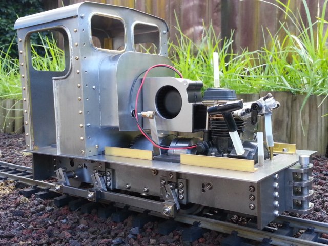
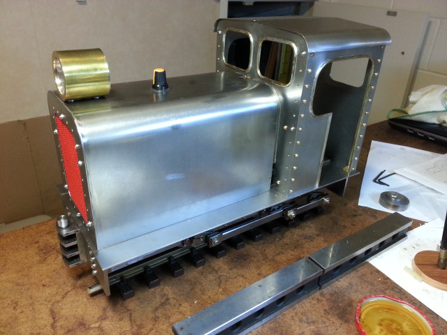
Yes, it's supposed to have louvered doors on the sides, but I'm too chicken / lazy. It was a bit of a mission cutting the cut-out, and laziness took it's toll again. There's going to be a fan above the flywheel / clutch blowing air over the engine and out from where the radiator would be. Air can be entrained from the new ventilation opening and from underneath - between the frames. I'm not a serious modeller, I quite like a toy like appearance. This project has been going on for far too long now, it's into the 3rd year nowphilipy:107658 wrote:That looks good.
TBH I've been thinking the bonnet looked very plain and "un-diesel-like"! So aside from the technical requirement IMO it improves the aesthetics as well.
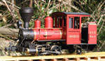
Live Diesel 1/12th scale
-
dewintondave
- Trainee Driver

- Posts: 697
- Joined: Mon Mar 07, 2011 8:52 am
- Location: New Zealand
Last edited by dewintondave on Sun Feb 09, 2020 4:40 am, edited 1 time in total.
Best wishes,
Dave
Dave
-
dewintondave
- Trainee Driver
- Posts: 697
- Joined: Mon Mar 07, 2011 8:52 am
- Location: New Zealand
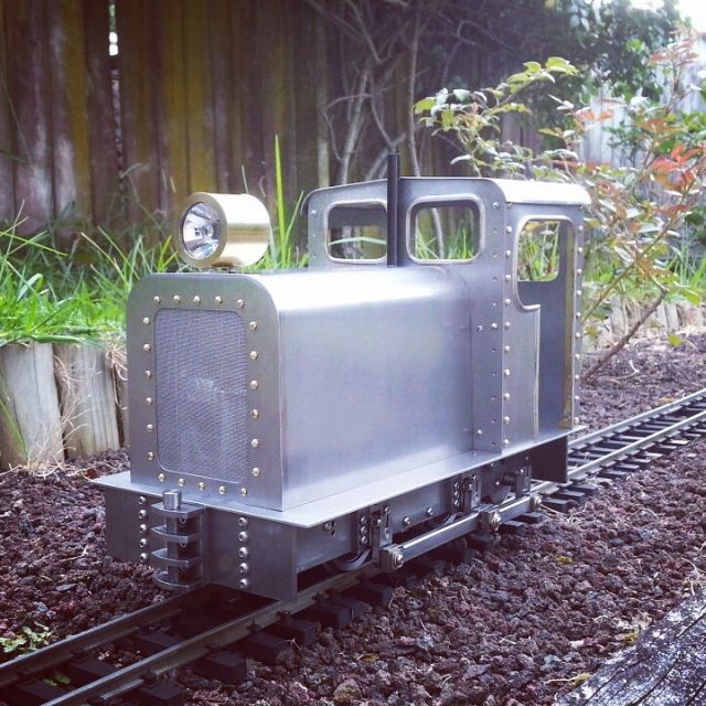
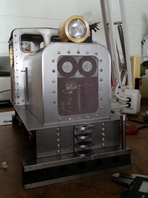
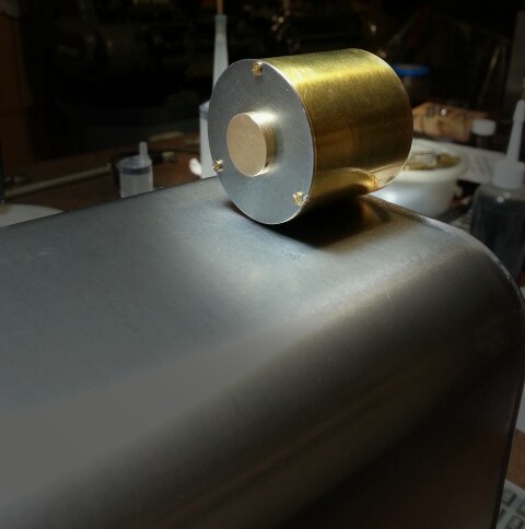
As I'm waiting for the cooling fan. I decided to add a headlight to the loco. This light was made from the lens, reflector, and bulb assembly of a small torch (flashlight). I'm fond of brass, so I'm thinking of keeping it polished. The back plate is steel, and that can be painted.

It's surprising how long it took to make. The outer shell is 0.5mm brass sheet and had to be annealed and rolled around a former. Then it had to be wired closed and then silver brazed. The 1.2mm brass end pieces had to be cut-out, then they were soft soldered to a chucking piece, then turned to size to fit the outer shell. They were then silver brazed one at a time into the shell and turned on the lathe. The ends were drilled and bored for the reflector and lens.
This is a large light. It officially fell off a much larger NZR locomotive, and was pressed into service.
Last edited by dewintondave on Sun Feb 09, 2020 4:43 am, edited 1 time in total.
Best wishes,
Dave
Dave
-
Peter Butler

- Driver

- Posts: 5234
- Joined: Sun Sep 09, 2012 10:33 pm
- Location: West Wales
I have only contributed to this thread once before and can only repeat what I said then.... this has been one incredible project and I have no ability to emulate your skills with metal or IC power.
Your understanding of the materials, process and manufacture have been second to none, even the descriptions have been outstanding.
My congratulations on (almost) completion of the model. Please show the loco in its final painted state before you close.
Your understanding of the materials, process and manufacture have been second to none, even the descriptions have been outstanding.
My congratulations on (almost) completion of the model. Please show the loco in its final painted state before you close.
The best things in life are free.... so why am I doing this?
-
dewintondave
- Trainee Driver
- Posts: 697
- Joined: Mon Mar 07, 2011 8:52 am
- Location: New Zealand
Thank you Peter, will do!Peter Butler:108242 wrote:My congratulations on (almost) completion of the model. Please show the loco in its final painted state before you close.
Last edited by dewintondave on Sun Feb 09, 2020 4:44 am, edited 1 time in total.
Best wishes,
Dave
Dave
-
invicta280
- Trainee Driver
- Posts: 664
- Joined: Wed Sep 21, 2011 9:24 pm
- Location: kent england
-
dewintondave
- Trainee Driver
- Posts: 697
- Joined: Mon Mar 07, 2011 8:52 am
- Location: New Zealand
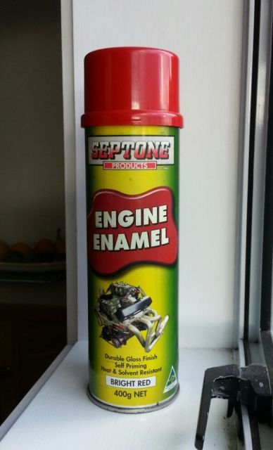
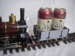
Thank you! NZR red-ish...invicta280:108266 wrote:Impressive model engineering Dave. Looks spectacular in the bare metal. Are you going to paint it NZR red?
btw are you a NI man or a southerner?
I'm up in the big smoke of the North Island
Last edited by dewintondave on Sun Feb 09, 2020 4:46 am, edited 1 time in total.
Best wishes,
Dave
Dave
-
dewintondave
- Trainee Driver
- Posts: 697
- Joined: Mon Mar 07, 2011 8:52 am
- Location: New Zealand
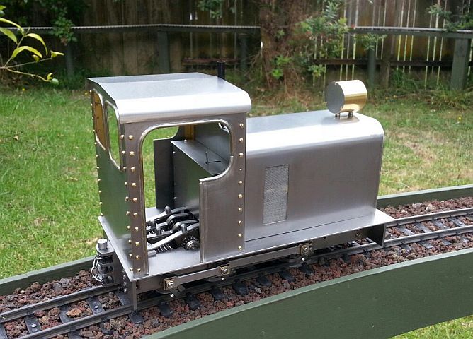
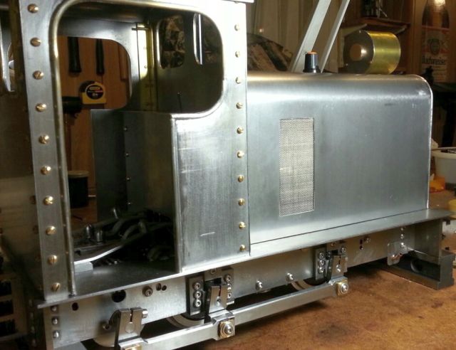
Well, I've finally got a cooling fan to try out, but first I thought I'd better fit the front grille. I didn't want to solder it directly in so had to cut out a steel retaining piece which sandwiches the mesh and is held in place with screws. Two days of sawing, filing, drilling and tapping.
Last edited by dewintondave on Sun Feb 09, 2020 4:48 am, edited 1 time in total.
Best wishes,
Dave
Dave
'Fess up, you enjoy that sort of thing or you wouldn't be building a live DM.........dewintondave:108517 wrote: Two days of sawing, filing, drilling and tapping.
It's looking good, but the engine doors do look a bit plain. Queensland cane tram style mesh openings might be worth considering as an alternative to louvres.
Coincidentally, your countryman Paul Berntsen has an article in the current issue of Narrow Gauge Downunder, showing how he built a 16mm scale Fowler PM. As is his way, he made a punch for forming louvres in the engine doors.
Regards,
Graeme
-
dewintondave
- Trainee Driver
- Posts: 697
- Joined: Mon Mar 07, 2011 8:52 am
- Location: New Zealand
Oh, I do enjoy it.GTB:108523 wrote:'Fess up, you enjoy that sort of thing or you wouldn't be building a live DM.........
It'll be time for some wiring soon.
Last edited by dewintondave on Sun Feb 09, 2020 4:49 am, edited 1 time in total.
Best wishes,
Dave
Dave
-
dewintondave
- Trainee Driver
- Posts: 697
- Joined: Mon Mar 07, 2011 8:52 am
- Location: New Zealand
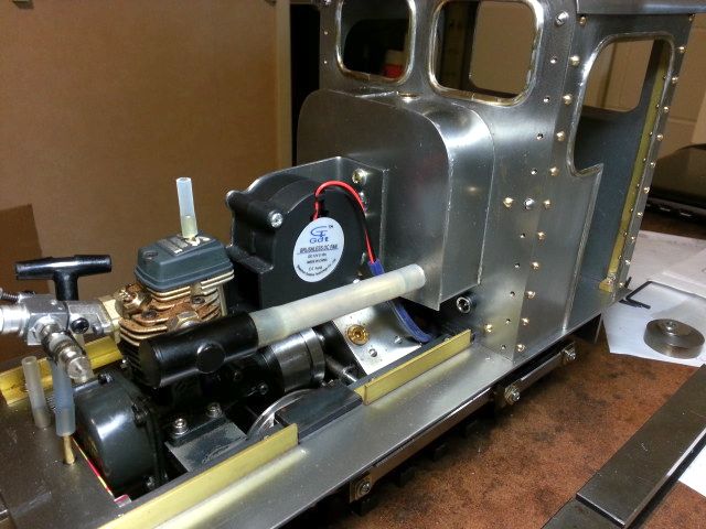
The project was slowed up by a slow delivery from Germany. I ended up fitting a centrifugal type blower fan to blow air across the cylinder fins. In all fairness the fan from Germany is excellent and almost silent (but I'm not using it after all, it's an axial type). Though having thought about it, silence isn't important in a live diesel set-up.
To help expel hot air from under the bonnet and through the mesh, I have installed two small fans at the top of the grille.
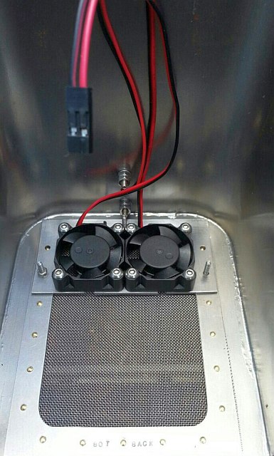
I need to sort out the electrics now. The fans are all 12V dc types
To help expel hot air from under the bonnet and through the mesh, I have installed two small fans at the top of the grille.
I need to sort out the electrics now. The fans are all 12V dc types
Last edited by dewintondave on Sun Feb 09, 2020 4:53 am, edited 2 times in total.
Best wishes,
Dave
Dave

-
dewintondave
- Trainee Driver
- Posts: 697
- Joined: Mon Mar 07, 2011 8:52 am
- Location: New Zealand
Thanks Jim. Just a basic red colour scheme, nothing fancy, this is a fun locoBig Jim:109590 wrote:Hello Dave,
I was reading this thread yesterday and was wondering when you would post more delights.
Any idea on a livery yet?
Last edited by dewintondave on Sun Feb 09, 2020 4:54 am, edited 1 time in total.
Best wishes,
Dave
Dave
-
dewintondave
- Trainee Driver
- Posts: 697
- Joined: Mon Mar 07, 2011 8:52 am
- Location: New Zealand
It's only a small issue, but I accidentally blew the 2.5V bulb in the headlamp by applying 6V to it. When I went to replace it, the new bulb was a good 1mm longer. It turns out that the original bulb was malformed and too short. I based the whole headlamp around that bulb, so I had to make an extender cap to fit over the rear cover. I've shifted to using 5.4 V bulbs from eBay now...
I've got a neat PWM controller from eBay to dim the headlight. I've been unsoldering the potentiometer from the PCB to remote mount it behind the headlight, I need the PCB to be horizontal.
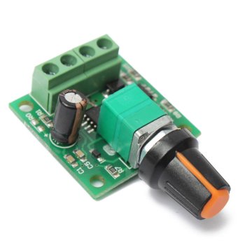
I've got a neat PWM controller from eBay to dim the headlight. I've been unsoldering the potentiometer from the PCB to remote mount it behind the headlight, I need the PCB to be horizontal.
Last edited by dewintondave on Sun Feb 09, 2020 5:58 am, edited 1 time in total.
Best wishes,
Dave
Dave
-
dewintondave
- Trainee Driver
- Posts: 697
- Joined: Mon Mar 07, 2011 8:52 am
- Location: New Zealand
Finally, I have something to show. The cooling arrangements have been wired-up and connected.
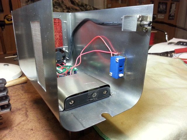
As soon as the bonnet is fully slid onto the loco the blue micro switch powers-up all the electrics. The electrical connector provides power for the loco mounted blower. There are 4 AA cells in the battery holder. The toy-like smooth exterior has been preserved with no through bonnet fixings for all the bits and pieces.
As soon as the bonnet is fully slid onto the loco the blue micro switch powers-up all the electrics. The electrical connector provides power for the loco mounted blower. There are 4 AA cells in the battery holder. The toy-like smooth exterior has been preserved with no through bonnet fixings for all the bits and pieces.
Last edited by dewintondave on Sun Feb 09, 2020 6:03 am, edited 1 time in total.
Best wishes,
Dave
Dave
-
dewintondave
- Trainee Driver
- Posts: 697
- Joined: Mon Mar 07, 2011 8:52 am
- Location: New Zealand
Here's a small video of the bonnet/hood in operation. The two small axial fans on the front take about 50 seconds to reach top speed, it must be a feature of their brushless controllers.
Last edited by dewintondave on Sun Feb 09, 2020 6:06 am, edited 1 time in total.
Best wishes,
Dave
Dave
-
dewintondave
- Trainee Driver
- Posts: 697
- Joined: Mon Mar 07, 2011 8:52 am
- Location: New Zealand
I don't want to have to remove the cooling hood when topping up the fuel so I've mounted an extension filler pipe on the right-hand side behind the buffer beam.

Some people ask if I have any drawings, well here's a circuit diagram I drew to work out the electrics. I didn't use the switch in the blower wiring in the end.
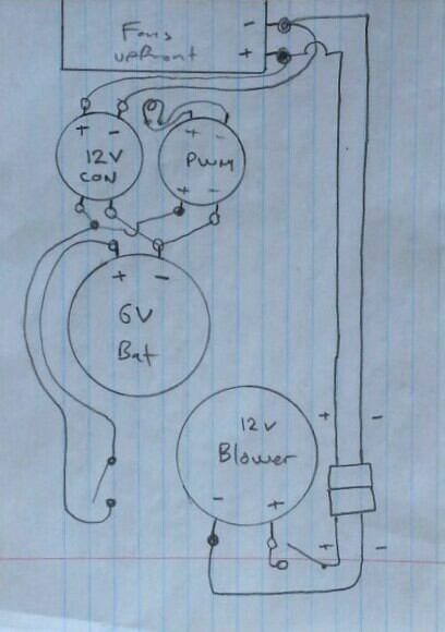
Some people ask if I have any drawings, well here's a circuit diagram I drew to work out the electrics. I didn't use the switch in the blower wiring in the end.
Last edited by dewintondave on Sun Feb 09, 2020 6:10 am, edited 1 time in total.
Best wishes,
Dave
Dave

-
dewintondave
- Trainee Driver
- Posts: 697
- Joined: Mon Mar 07, 2011 8:52 am
- Location: New Zealand
Thank you guys.
I've just finalised the filler. The pipe needed holding place to resist the filler connection force.
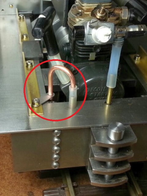
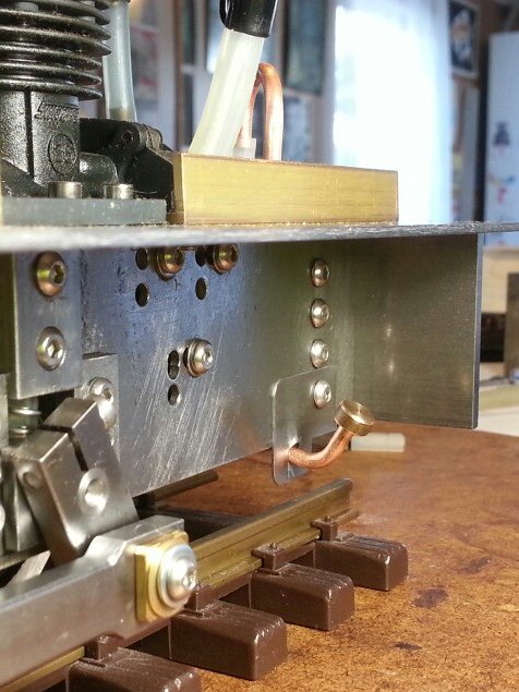
I've just finalised the filler. The pipe needed holding place to resist the filler connection force.
Last edited by dewintondave on Sun Feb 09, 2020 6:12 am, edited 1 time in total.
Best wishes,
Dave
Dave
-
dewintondave
- Trainee Driver
- Posts: 697
- Joined: Mon Mar 07, 2011 8:52 am
- Location: New Zealand
At last we had a break from the rain and I was able to test the cooling fans for the first time in use. The fans appear to be effective. After the run, (the tankful was consumed after 17 minutes) fans were left running for a while, and the cylinder head was just warm. The bonnet / hood rattled at times. From analysis after the run, I found that the motor was running 30% too fast, and the loco was doing about 6.5 scale MPH.
Last edited by dewintondave on Sun Feb 09, 2020 6:15 am, edited 1 time in total.
Best wishes,
Dave
Dave
Who is online
Users browsing this forum: No registered users and 6 guests