
Live Diesel 1/12th scale
-
dewintondave

- Trainee Driver

- Posts: 697
- Joined: Mon Mar 07, 2011 8:52 am
- Location: New Zealand
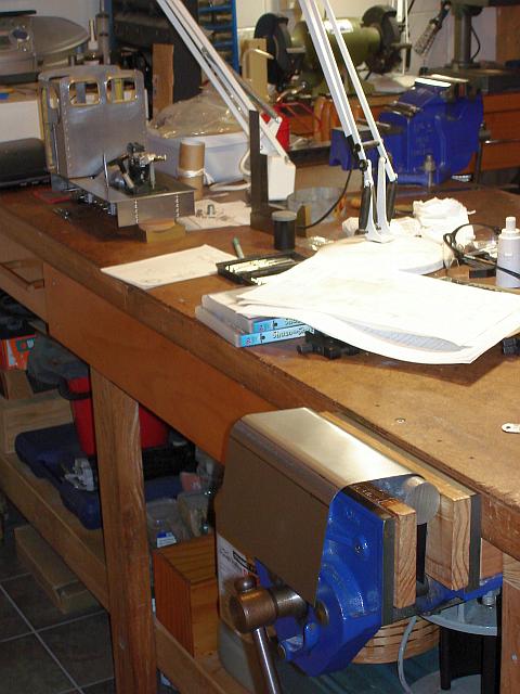
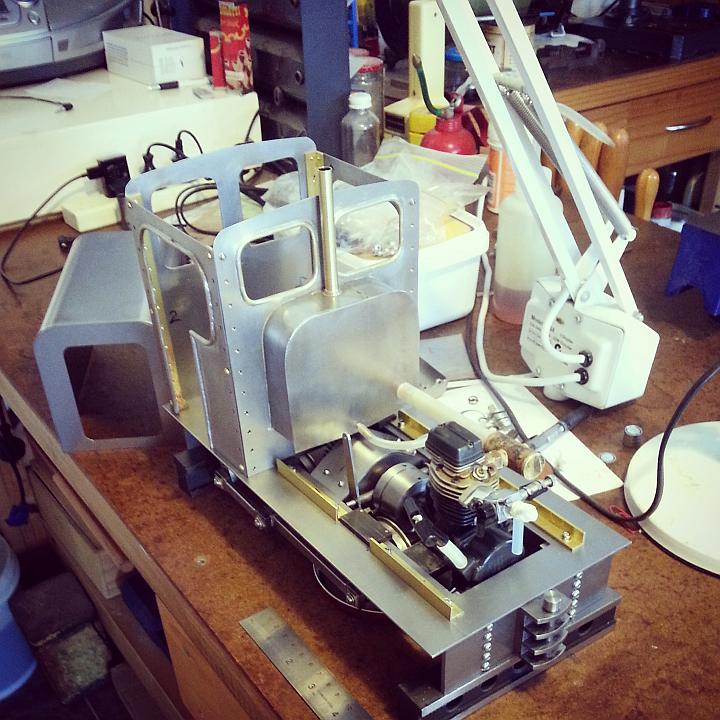
Well, the cab is nearing completion. All the beading is on. It is time to make a gentle start on the bonnet.
Last edited by dewintondave on Sun Feb 09, 2020 2:31 am, edited 1 time in total.
Best wishes,
Dave
Dave
-
dewintondave
- Trainee Driver
- Posts: 697
- Joined: Mon Mar 07, 2011 8:52 am
- Location: New Zealand
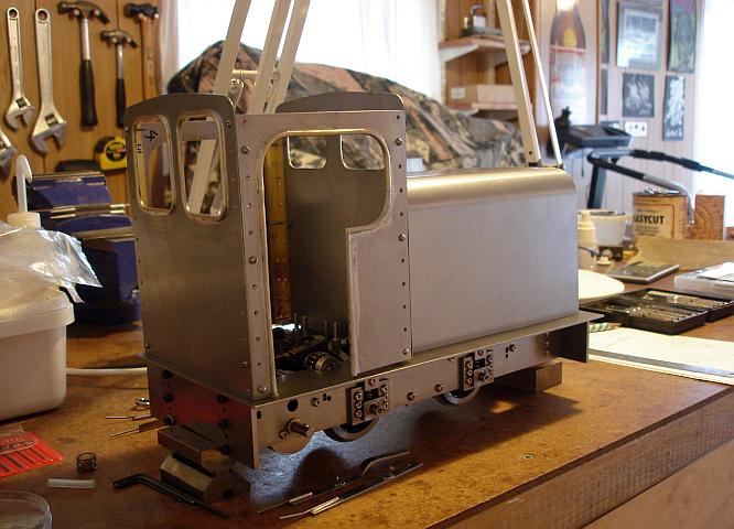
Here we are, I've bent up the bonnet in the wood vice. I like the end-on view, it's got that menacing look of the truck in "Duel" (I could put some battered old engine nameplates along the buffer beam of victims, lol).
Last edited by dewintondave on Sun Feb 09, 2020 2:34 am, edited 1 time in total.
Best wishes,
Dave
Dave

-
Peter Butler

- Driver

- Posts: 5234
- Joined: Sun Sep 09, 2012 10:33 pm
- Location: West Wales
I have watched this thread from beginning to present and up 'till now have nothing to contribute to the project..... but I must say I am in awe of your engineering skills, combined with the infinite amount of patience you have shown in developing this loco.
Even your workshop is neat and tidy..... I must lie down now!.
Even your workshop is neat and tidy..... I must lie down now!.
-
dewintondave
- Trainee Driver
- Posts: 697
- Joined: Mon Mar 07, 2011 8:52 am
- Location: New Zealand
Thanks chaps. When I was younger I had little patience, let's hope I keep it up
Last edited by dewintondave on Sun Feb 09, 2020 2:36 am, edited 1 time in total.
Best wishes,
Dave
Dave
-
dewintondave
- Trainee Driver
- Posts: 697
- Joined: Mon Mar 07, 2011 8:52 am
- Location: New Zealand
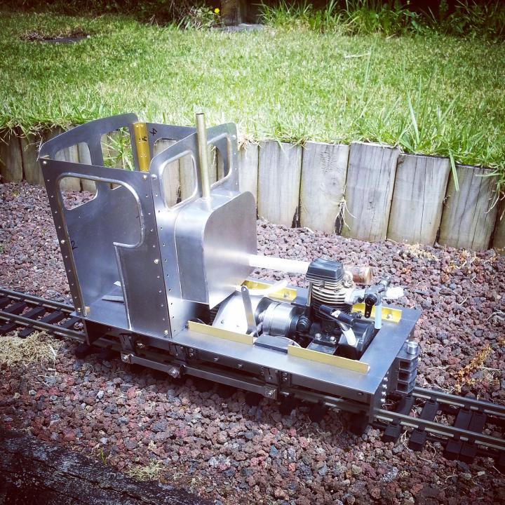
Here's the latest progress, the side rods fitted, a test run on the line - pushed by hand...
The motion is a bit tight, it needs a good run under power.
The motion is a bit tight, it needs a good run under power.
Last edited by dewintondave on Sun Feb 09, 2020 2:38 am, edited 1 time in total.
Best wishes,
Dave
Dave

-
dewintondave
- Trainee Driver
- Posts: 697
- Joined: Mon Mar 07, 2011 8:52 am
- Location: New Zealand
I could run it now with the remote tank. It needs a good run as the motion is quite tight...laalratty:103581 wrote:That really looks like its coming together nicely, how far from running is it?
Last edited by dewintondave on Sun Feb 09, 2020 3:00 am, edited 1 time in total.
Best wishes,
Dave
Dave
-
dewintondave
- Trainee Driver
- Posts: 697
- Joined: Mon Mar 07, 2011 8:52 am
- Location: New Zealand
Finally, I got the loco running again. Last weekend I had lots of fun soldering up a small on-board fuel tank from a can. It only holds about 40 mL, but it lasts for 20 minutes and can be topped-up when running.
Just keep filling until fuel comes out the overflow.
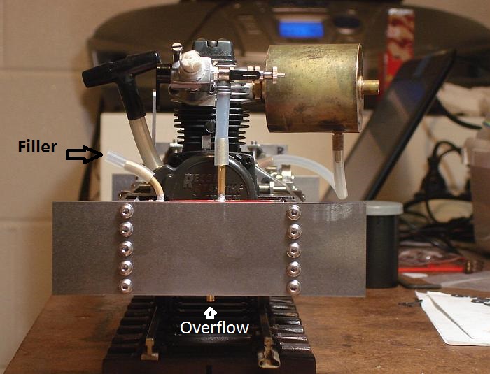
Video of the run
Just keep filling until fuel comes out the overflow.
Video of the run
Last edited by dewintondave on Sun Feb 09, 2020 3:05 am, edited 1 time in total.
Best wishes,
Dave
Dave


-
dewintondave
- Trainee Driver
- Posts: 697
- Joined: Mon Mar 07, 2011 8:52 am
- Location: New Zealand
Thank you Annie.Annie:105276 wrote:What a beautiful example of model engineering :D
---
I've been making multi-height couplings for the loco, these are chunky fabrications and have taken a long time...

Last edited by dewintondave on Sun Feb 09, 2020 3:07 am, edited 1 time in total.
Best wishes,
Dave
Dave

-
dewintondave
- Trainee Driver
- Posts: 697
- Joined: Mon Mar 07, 2011 8:52 am
- Location: New Zealand
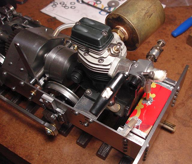
Recently I've been concentrating on the exhaust system. A manifold to turn the exhaust through 98 deg. Then a huge box for the gasses to expand in, and then exhaust pipe going up the front middle of the cab in between the windows. The exhaust box is all soft soldered together, and coated all over the inside surface with solder to protect the mild steel. The exhaust box has a capacity of about 200mL.
There's the oil drain at the base of the exhaust box.
There's the oil drain at the base of the exhaust box.
Last edited by dewintondave on Sun Feb 09, 2020 3:11 am, edited 1 time in total.
Best wishes,
Dave
Dave
-
dewintondave
- Trainee Driver
- Posts: 697
- Joined: Mon Mar 07, 2011 8:52 am
- Location: New Zealand
Thank you!laalratty:106099 wrote:Really does look excellent, the standard of work looks very high indeed.
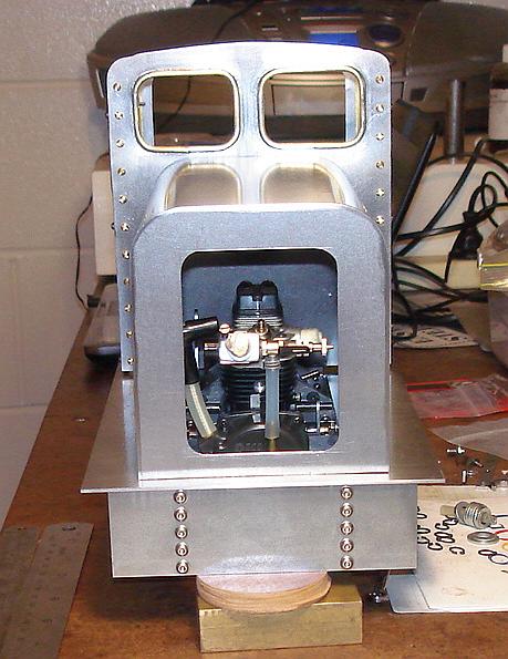
I've been sorting out the gear lever arrangement. Here's a view through the cab door way.
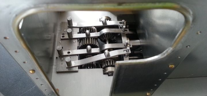
The pins on the ends locate the levers in the right position. The knobs in the middle are for fingers to push/pull the levers. The two outer levers are forward (nearest), and reverse. Each lever has an in-gear position and a out-of-gear position. The two inner levers are for the different ratios. First - Neutral - Third, and Neutral - Second.
In the picture the loco is in First gear, but not in either Forward or Reverse. This way the loco can be pushed along
Last edited by dewintondave on Sun Feb 09, 2020 3:14 am, edited 1 time in total.
Best wishes,
Dave
Dave
-
dewintondave
- Trainee Driver
- Posts: 697
- Joined: Mon Mar 07, 2011 8:52 am
- Location: New Zealand
Had a great run yesterday. The run was to test the huge new muffler / silencer box attached to the cab firewall. There's so much expansion, that the exhaust gasses are quite cold exiting the exhaust stack. The muffler is very effective, there's little exhaust noise. However, there's a lot of mechanical noise from the motor itself, and there's a ringing noise from the muffler as it flexes, I'll put a stay in the middle to stop it.
The video was taken shortly after starting, I was draining off the oil until the good stuff started coming through, then reconnected a tube to the primary gearbox. I topped-up the fuel tank three times with the engine running. I felt like the run was about an hour. The loco went up and down the short section of track in all three gears, third is really rather rapid!
I measured some temperatures during the run with my eBay IR handheld thermometer:
I got cylinder head temperatures of 150 - 190 deg. C (300 - 370 deg. F).
And, the muffler box itself was only 70 deg. C (160 deg. F), which is lucky as it's only soft-soldered.
The motor wouldn't start with the exhaust stack fitted, so I replaced it once running. It's a slide-fit in the muffler
Last edited by dewintondave on Sun Feb 09, 2020 3:21 am, edited 1 time in total.
Best wishes,
Dave
Dave
Very, Very Impressive.
Regarding the noise from the muffler. You could try attaching a small bit of lead or similar to the side. All that you may need to do is stop the metal vibrating at a certain frequency to stop the noise. The small additional bit of dense material will change the frequency and the noise may change or disappear.
(car manufacturers use this technique to stop strange resonations in vehicles.)
If at first you don't succeed, use a bigger hammer!
-
dewintondave
- Trainee Driver
- Posts: 697
- Joined: Mon Mar 07, 2011 8:52 am
- Location: New Zealand
Thank you Big Jim.Big Jim:106329 wrote:Very, Very Impressive.
Regarding the noise from the muffler. You could try attaching a small bit of lead or similar to the side. All that you may need to do is stop the metal vibrating at a certain frequency to stop the noise. The small additional bit of dense material will change the frequency and the noise may change or disappear.
(car manufacturers use this technique to stop strange resonations in vehicles.)
Best wishes,
Dave
Dave
-
dewintondave
- Trainee Driver
- Posts: 697
- Joined: Mon Mar 07, 2011 8:52 am
- Location: New Zealand
I've been having doubts about reusing the engine oil in the gearbox. With the old set-up the oil came from the very hot muffler. With the new set-up it's a lot cooler and solid droplets of water come down the tube with the oil.
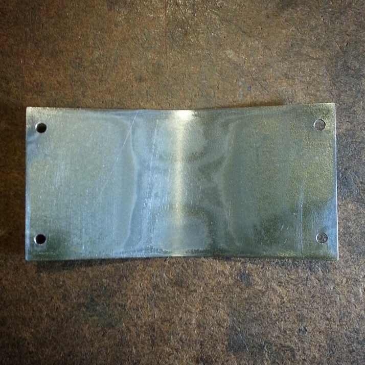
I removed the lower gearbox cover, and this is what I found: The grey particles are metal fragments. I spent hours deburring these gears by hand when I made them.
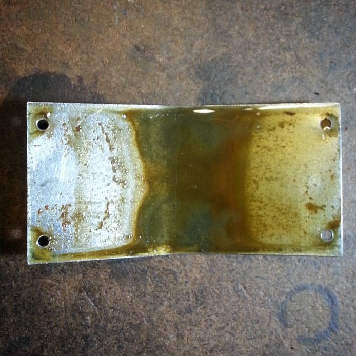
All the muck and gunk wiped off easily with a paper towel. There is evidence of light erosion from where the oil sits in the trough, but no red rust.
I removed the lower gearbox cover, and this is what I found: The grey particles are metal fragments. I spent hours deburring these gears by hand when I made them.
All the muck and gunk wiped off easily with a paper towel. There is evidence of light erosion from where the oil sits in the trough, but no red rust.
Last edited by dewintondave on Sun Feb 09, 2020 3:24 am, edited 1 time in total.
Best wishes,
Dave
Dave
Who is online
Users browsing this forum: No registered users and 4 guests