The sample was edited to sound acceptable when looping on a PC before being flashed to the micro. The t85 has 8K of flash, and the sample rate is 8kHz, giving a maximum of 1 second of audio. The code on the micro is very simple, two timers are set up, one to output a fairly fast PWM signal on the base of the transistor and one that triggers an interrupt at 8kHz to load the next sample value from flash into the PWM output. When the micro reaches the last sample value, it just loads the first one again and continues, so the quality of the loop transition in this case mostly depends on the quality of the sample itself, not so much the hardware. One way to get the loop to sound a little better I found was to cut the sample at zero crossings, as it tended to have fewer glitches.ge_rik wrote: ↑Wed Aug 09, 2017 7:40 am Just wondering if this ought to be on a new thread ......
Intrigued by this circuit. A problem I've been having with simple sound circuits is overcoming a silent pause each time the sound loops back to the start. Just wondered whether this was a problem for you and how you overcame it - or whether it's not an issue with the sound sample being so short.
Rik
Dunitrong Locomotive Works
-
metalmuncher
- Cleaner

- Posts: 95
- Joined: Sat Oct 20, 2012 4:15 pm
Re: Re:

Re: Re:
Thanks. I'll pretend I understand all of that. It'll probably make more sense when I start fiddling.metalmuncher wrote: ↑Wed Aug 09, 2017 5:11 pm The sample was edited to sound acceptable when looping on a PC before being flashed to the micro. The t85 has 8K of flash, and the sample rate is 8kHz, giving a maximum of 1 second of audio. The code on the micro is very simple, two timers are set up, one to output a fairly fast PWM signal on the base of the transistor and one that triggers an interrupt at 8kHz to load the next sample value from flash into the PWM output. When the micro reaches the last sample value, it just loads the first one again and continues, so the quality of the loop transition in this case mostly depends on the quality of the sample itself, not so much the hardware. One way to get the loop to sound a little better I found was to cut the sample at zero crossings, as it tended to have fewer glitches.
Rik
Re: Dunitrong Locomotive Works
Another year, another new electric loco project!
This one has been 3D printed on my son's printer, user arockStone on thingiverse put up the files for this for free: https://www.thingiverse.com/thing:2109286 so many thanks to him.
It starts off as a kit of parts, here it is straight off the printer:
The parts are a little rough. The printer is not perfectly dialed in, on reflection it might be better in future to print the body in larger pieces, perhaps layer lines will be easier to smooth compared to bumpy solid top infill.
The parts are simply glued together, sometimes using plastic angle for extra strength. The panels are filled, sanded and smoothed to try and increase the surface quality. Parts like the horn and exhaust don't make sense to 3D print, traditional modelling materials are just easier. The filler primer used was a yellow colour, it seemed to fit the loco quite nice so it was decided that the final colour would be yellow.
The original design called for a basic chassis from IP. An attempt was made to make one from sheet metal, which resulted in failure due to the metal twisting during machining. The model files include a 3d printed one, and this seemed to work quite well. Brass top hat bushes were heated and then pushed into the plastic chassis with a drill press, resulting in a smooth running chassis. The wheels were turned on my Myford lathe, with the help of some homemade tools to speed up the process.
We had a spare Deltang receiver, but it decided to start acting up not wanting to bind. And alternative was made by my son. This consisted of a cheap commercial receiver, and an arduino clone and hacked together motor driver board that fits on the arduino. The battery is a 2000mAh lithium polymer one. It is an extremely tight fit under the bonnet, the lipo fits snugly along one side of the engine compartment, with the other boards on the other two sides and the motor in the middle.
An interior was constructed from mostly wood, with a few bits of paper drawn on and stuck down for a control panel.
With a few extra details and a coat of paint I think the loco has come out quite well. Material cost was quite low, maybe £3-4 of plastic, and £15 for receiver gear, and a few pounds more for the various other bits and bobs.
I am well pleased with how the chassis turned out. It is one of the quietest running engines we have, the drive is barely audible over rickety wagons, although it does exhibit the typical rattle that worm driven engines seem to have when running in reverse.
The electric engine shelf is starting to get a bit full, I still have an IP lister and Essel chassis to build... more space needed!
This one has been 3D printed on my son's printer, user arockStone on thingiverse put up the files for this for free: https://www.thingiverse.com/thing:2109286 so many thanks to him.
It starts off as a kit of parts, here it is straight off the printer:
- 1.JPG (152.71 KiB) Viewed 13556 times
- 2.jpg (124.31 KiB) Viewed 13556 times
- 3.JPG (83.54 KiB) Viewed 13556 times
- 4.jpg (134.53 KiB) Viewed 13556 times
- 5.JPG (116.24 KiB) Viewed 13556 times
- 6.JPG (127.27 KiB) Viewed 13556 times
I am well pleased with how the chassis turned out. It is one of the quietest running engines we have, the drive is barely audible over rickety wagons, although it does exhibit the typical rattle that worm driven engines seem to have when running in reverse.
- 7.JPG (42 KiB) Viewed 13556 times
Re: Dunitrong Locomotive Works
That's a nice little loco and runs well.
I've seen that on Thingiverse myself and wondered if it was worth giving it a go.
What filament did you use?
I've seen that on Thingiverse myself and wondered if it was worth giving it a go.
What filament did you use?
Philip
-
metalmuncher
- Cleaner
- Posts: 95
- Joined: Sat Oct 20, 2012 4:15 pm
Re: Dunitrong Locomotive Works
Its printed in PLA from rigid.ink. It's a bit pricey, but I've found it consistent and don't want to be messing with the tuning too much now I'm getting acceptable results. A few parts did warp slightly, it might've been better to print them with a removable brim to make sure they stick well to the bed.
Re: Dunitrong Locomotive Works
Thanks.metalmuncher wrote: ↑Sun Feb 04, 2018 7:36 pmIts printed in PLA from rigid.ink. It's a bit pricey, but I've found it consistent and don't want to be messing with the tuning too much now I'm getting acceptable results. A few parts did warp slightly, it might've been better to print them with a removable brim to make sure they stick well to the bed.
Yes I use Rigid Ink myself. They are pricey compared to some but actually given the amount that any given part uses, its negligable in reality and worth it for the service and reliability.
I tend to use a brim or raft for everything, anyway.
I think I might see what I can do with this, because I've had an IP chassis kit sitting sitting on the shelf for about 5 years an I keep wondering what to do with it....
Philip

Re: Dunitrong Locomotive Works
What a brilliant build, it looks fantastic... 
ROD
Life is so easy when I run my trains.


https://gardenrails.org/forum/viewtopic ... 41&t=11364
https://www.youtube.com/@fairywoodlightrailway
Life is so easy when I run my trains.


https://gardenrails.org/forum/viewtopic ... 41&t=11364
https://www.youtube.com/@fairywoodlightrailway
Re: Dunitrong Locomotive Works
Thanks for that. We are working on another loco using some parts left over from this one. It will be cabless with a printed engine. Things have come to a holt at the moment with hospital appointments.But nothing serious.Arthur
Re: Dunitrong Locomotive Works
Would you consider making more of them. :thumb right:
ROD
Life is so easy when I run my trains.
https://gardenrails.org/forum/viewtopic ... 41&t=11364
https://www.youtube.com/@fairywoodlightrailway
Life is so easy when I run my trains.
https://gardenrails.org/forum/viewtopic ... 41&t=11364
https://www.youtube.com/@fairywoodlightrailway
-
metalmuncher
- Cleaner
- Posts: 95
- Joined: Sat Oct 20, 2012 4:15 pm
Re: Dunitrong Locomotive Works
If you're looking to get hold of the parts for this to make one for yourself, you could look at 3Dhubs: https://www.3dhubs.com/3d-printing
They are essentially a go between for people who want things printed and people who have printers. Hopefully better printers than mine, which is held together with tie wraps and hope. Its not suitable for any kind of production use at the minute - too many failures. In fact, here is my box of failed prints so far:
- IMG_20180303_110403.jpg (30.19 KiB) Viewed 13206 times
Re: Dunitrong Locomotive Works
Thank you 
ROD
Life is so easy when I run my trains.
https://gardenrails.org/forum/viewtopic ... 41&t=11364
https://www.youtube.com/@fairywoodlightrailway
Life is so easy when I run my trains.
https://gardenrails.org/forum/viewtopic ... 41&t=11364
https://www.youtube.com/@fairywoodlightrailway
-
invicta280
- Trainee Driver

- Posts: 664
- Joined: Wed Sep 21, 2011 9:24 pm
- Location: kent england
Re: Dunitrong Locomotive Works
Handsome loco and very striking in smart safety yellow.
-
metalmuncher
- Cleaner
- Posts: 95
- Joined: Sat Oct 20, 2012 4:15 pm
Re: Dunitrong Locomotive Works
I'm posting my dad's latest project on his behalf, I suppose its a sort of one-off kit for him made by me.
We've had these Andel balcony coaches for years, my dad really likes them, and has been wanting a railcar for some time.

I've had one of those Chinese K40 CO2 laser cutters for a couple of years, but haven't really been able to get much use out of it yet. I've made many modifications, even built a new shed in the garden to house it last year. Now its at a point where its pretty usable, so I wanted a project to to start learning with.
I started drawing up a railcar in the Andel coach style about a month ago in Fusion 360. It ends up with some "interesting" proportions, definitely would need to duck under the doors, but its in keeping with the existing coaches.

Both bogies were designed to be 3D printed. I made a prototype chassis to test. I tried giving giving the rear a bit of pitch compensation as well. At this point the chassis seemed to work well...

I decided to try and give my dad the basic body kit for Father's Day, ended up running into issues with keeping the laser cool, but got most of the wood cut out by the Sunday morning.

All the laser cut bits. Ended up with a few issues with things not fully cutting through, but all a learning experience. The fits for the tab and slot construction came out quite nice, the result when put together was very solid.


We thought it looked a bit odd not having any detailing at all for the doors on the inside. I found some cardboard out of the bin (one of those Amazon cardboard envelopes) and tried cutting out some doors on the laser. I think this worked out quite well - super cheap and quick. Maybe on the next model a full interior could be detailed with cardboard overlays. I didn't give him any cab detailing in the 'kit', left that up for him to come up with.


Started to look at the chassis, now the issues begin. I turned & milled some brass crank pins, M2 thread for a captive nut in the back of the printed wheels. This worked out OK, once the connecting rods were thinned down for clearance, but quartering was not easy. I printed up some jigs but it didn't really help, the idea was to hold the wheels with superglue, but it wasn't very strong and was difficult to keep everything free. The slightest knock and the quartering could go.


So we've just tried milling flats on to the axles, and printing the wheels with a matching flat - turned 90 degrees for one side to get the quartering. The wheels have a slight wobble but the quartering is easy and strong, seems to be working OK.

I got the idea for a ball joint for the front bogie from forum member Gile's Ashanti Bagnall build: https://www.youtube.com/watch?v=ndCPUi-3e94 As it is it provides a lot of articulation to follow a rough track, probably too much, but the socket block is easily replaced with a modified version.

So that's where we're up to today, tested ok pushing one of the coaches up the section of track clear of vegetation, just needs a bit more traction, some lead weights might help.

We've had these Andel balcony coaches for years, my dad really likes them, and has been wanting a railcar for some time.
I've had one of those Chinese K40 CO2 laser cutters for a couple of years, but haven't really been able to get much use out of it yet. I've made many modifications, even built a new shed in the garden to house it last year. Now its at a point where its pretty usable, so I wanted a project to to start learning with.
I started drawing up a railcar in the Andel coach style about a month ago in Fusion 360. It ends up with some "interesting" proportions, definitely would need to duck under the doors, but its in keeping with the existing coaches.
Both bogies were designed to be 3D printed. I made a prototype chassis to test. I tried giving giving the rear a bit of pitch compensation as well. At this point the chassis seemed to work well...
I decided to try and give my dad the basic body kit for Father's Day, ended up running into issues with keeping the laser cool, but got most of the wood cut out by the Sunday morning.
All the laser cut bits. Ended up with a few issues with things not fully cutting through, but all a learning experience. The fits for the tab and slot construction came out quite nice, the result when put together was very solid.
We thought it looked a bit odd not having any detailing at all for the doors on the inside. I found some cardboard out of the bin (one of those Amazon cardboard envelopes) and tried cutting out some doors on the laser. I think this worked out quite well - super cheap and quick. Maybe on the next model a full interior could be detailed with cardboard overlays. I didn't give him any cab detailing in the 'kit', left that up for him to come up with.
Started to look at the chassis, now the issues begin. I turned & milled some brass crank pins, M2 thread for a captive nut in the back of the printed wheels. This worked out OK, once the connecting rods were thinned down for clearance, but quartering was not easy. I printed up some jigs but it didn't really help, the idea was to hold the wheels with superglue, but it wasn't very strong and was difficult to keep everything free. The slightest knock and the quartering could go.
So we've just tried milling flats on to the axles, and printing the wheels with a matching flat - turned 90 degrees for one side to get the quartering. The wheels have a slight wobble but the quartering is easy and strong, seems to be working OK.
I got the idea for a ball joint for the front bogie from forum member Gile's Ashanti Bagnall build: https://www.youtube.com/watch?v=ndCPUi-3e94 As it is it provides a lot of articulation to follow a rough track, probably too much, but the socket block is easily replaced with a modified version.
So that's where we're up to today, tested ok pushing one of the coaches up the section of track clear of vegetation, just needs a bit more traction, some lead weights might help.


Re: Dunitrong Locomotive Works
That is quite impressive, and would make a nice addition to many a railway 

Re: Dunitrong Locomotive Works
Thanks for the detailed description of the railcar's inception and construction. It certainly does look the part! I'll be really interested in seeing how it progresses. I've fought shy of 3D printing wheels and chassis parts up to now, so your conclusions about these are very welcome.
Rik
Rik
Re: Dunitrong Locomotive Works
It's looking good Richard. I do like the varnished wood effect.metalmuncher wrote: ↑Wed Jun 29, 2022 10:08 pm
The wheels have a slight wobble but the quartering is easy and strong, seems to be working OK.
I always end up with wobble using printed wheels. I guess with me it's from using a bench vice rather than a proper wheel press.
Philip
Re: Dunitrong Locomotive Works
Looking good. I wouldn't worry about the passengers having to duck to enter, most early railmotors were tiny things, look at the size of the Wee Donegal's first one........
Laser cutting has a lot to recommend it for model making, especially flat panels.
The d shaped axle is self quartering and probably as good as anything else you could use.
I don't like the look of the wheel flanges though, too thick and what looks like a ridge on the front face. I'd be giving them a skim in the lathe, which should reduce any slight wobble as well.
Regards,
Graeme
Laser cutting has a lot to recommend it for model making, especially flat panels.
As you found out, superglue is useless as a retaining compound. I use Loctite 601 for fitting metal wheels to axles on live steamers, but I've no experience of using it with plastic wheels. The current equivalent is Loctite 609, I think.metalmuncher wrote: ↑Wed Jun 29, 2022 10:08 pm the idea was to hold the wheels with superglue, but it wasn't very strong and was difficult to keep everything free. The slightest knock and the quartering could go.
The d shaped axle is self quartering and probably as good as anything else you could use.
I don't like the look of the wheel flanges though, too thick and what looks like a ridge on the front face. I'd be giving them a skim in the lathe, which should reduce any slight wobble as well.
Plastic wheels won't be helping traction, but lumps of metal for the cab control panel and drivers seat will sit over the power bogie and should do the job.metalmuncher wrote: ↑Wed Jun 29, 2022 10:08 pm So that's where we're up to today, tested ok pushing one of the coaches up the section of track clear of vegetation, just needs a bit more traction, some lead weights might help.
Regards,
Graeme
-
metalmuncher
- Cleaner
- Posts: 95
- Joined: Sat Oct 20, 2012 4:15 pm
Re: Dunitrong Locomotive Works
Good points there Graeme.
The wheel profile is mostly to the 16mm association spec, so 1.5mm flanges:
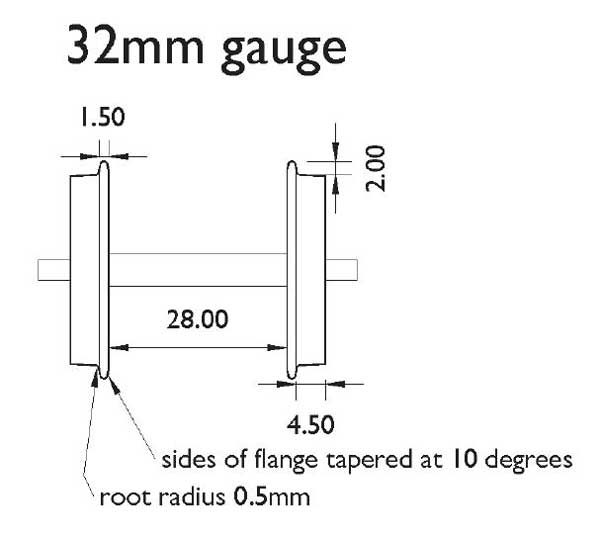
They are only 20mm diameter on the treads, so that might be causing the flanges to look a bit big compared to more standard sized wheels.
These were supposed to be test pieces, printed at a coarser layer height resulted in that step in the flange.
I did actually try turning some of these plastic wheels. The surface finish left a lot to be desired. The form tool has clearances but no top rake, not very sharp, so probably not ideal for plastic.
This was with some matte black filament though. Turing the grey stuff seemed to go a bit better. Might give it another go this weekend. If the wheels are painted black before turning, the turning will expose the grey on the treads and flange, might look a bit nicer for not much effort as well.
The wheel profile is mostly to the 16mm association spec, so 1.5mm flanges:
They are only 20mm diameter on the treads, so that might be causing the flanges to look a bit big compared to more standard sized wheels.
These were supposed to be test pieces, printed at a coarser layer height resulted in that step in the flange.
I did actually try turning some of these plastic wheels. The surface finish left a lot to be desired. The form tool has clearances but no top rake, not very sharp, so probably not ideal for plastic.
- 14.jpg (65.98 KiB) Viewed 4283 times
Re: Dunitrong Locomotive Works
Sounds like a plan......... 
I use the G1MRA coarse profile, which is pretty much the same as the SM32 one you use. I use a simple rounded tool to turn the tread and form the flange root radius, then a file to chamfer the back and round the outer corners of the flange. Form tools and I don't get on well.
I've never machined any printed plastic parts, but FDM prints are effectively sintered plastic, so I wouldn't be surprised if they won't machine all that cleanly. I've seen solvent used to smooth out the surface on FDM prints, so see no reason why it wouldn't work to smooth out the tread of a printed wheel after turning.
Interesting idea to print wheels in grey plastic and leaving the tread unpainted. The only plastic wheels I use are Binnie curly spoke type on timber bogies. The wheels are moulded in black, so I paint the treads a metallic grey. They look good for a while, but the paint inevitably wears off.
Graeme
Re: Dunitrong Locomotive Works
I tried this once, using the resin printer rather than FDM, and wasn't over happy. The resin is a bit paler grey than many filaments, and the black is only crudely applied, but it doesn't look realistic to my eyes.
- file.jpg (223.12 KiB) Viewed 4244 times
Philip
Who is online
Users browsing this forum: No registered users and 12 guests