Little Wonder

Discussion of Live Steam locomotives should be located here
Trevor Thompson
Trainee Driver
Trainee Driver
Posts: 963
Joined: Fri Oct 05, 2018 6:30 pm
Location: South West Wales

Little Wonder

Post by Trevor Thompson » Thu Jan 20, 2022 12:00 pm

I have started yet another project. Probably a long term project.

A proper metal model of Little Wonder. Although thoughts of 3 D printing wheel centres are already creeping in!

So to start with the drawings from "Fairly Locomotives of North Wales" by David Payning are loaded into a Sketchup file, and set out at to help with the design.

So far I have planned the two bogies, the valve gear, the boiler and its cradle:
Screen Shot 2022-01-20 at 10.37.12.png
Screen Shot 2022-01-20 at 10.37.12.png (458.45 KiB) Viewed 7517 times
This is the first time I have used this programme to design something to be built in metal - as in not just as a starting point for 3 D printing. I have already found the ability to place components in the correct relationship to each other quite a benefit. I am trying to think ahead and for example drill all the holes in the frames at the beginning rather than having to take things to pieces to drill extra holes half way through.I have worked out how the valve gear will work out, and the way the cylinders will fit with the valve chest and the frames.

Trevor

Trevor Thompson
Trainee Driver
Trainee Driver
Posts: 963
Joined: Fri Oct 05, 2018 6:30 pm
Location: South West Wales

Re: Little Wonder

Post by Trevor Thompson » Thu Jan 20, 2022 12:23 pm

So I have actually started to cut metal.

The 4 pieces of steel for the bogie frames were soldered together. Not very well as it turned out, which I discovered while milling the combined unit. It was easily solved by drilling the 1.8mm holes (clearance for 10BA) and bolting it all together.

I have recently realised that I can extract the engineering "sketches" that I want for use in the workshop by arranging the view in the CAD programme, and taking a screenshot. ( you can't print drawings from the free version of Sketchup).

So the bogie frames:
Screen Shot 2022-01-20 at 10.32.25.png
Screen Shot 2022-01-20 at 10.32.25.png (128.31 KiB) Viewed 7517 times
Trevor
Last edited by Trevor Thompson on Fri Feb 04, 2022 3:18 pm, edited 1 time in total.

Trevor Thompson
Trainee Driver
Trainee Driver
Posts: 963
Joined: Fri Oct 05, 2018 6:30 pm
Location: South West Wales

Re: Little Wonder

Post by Trevor Thompson » Thu Jan 20, 2022 12:26 pm

Milling the frames:
IMG_2058.jpg
IMG_2058.jpg (2.15 MiB) Viewed 7515 times
All a bit messy, which is why I like working with brasses, rather then steels!

and the finished frames separated:
IMG_2062.jpg
IMG_2062.jpg (1.68 MiB) Viewed 7515 times
Trevor

User avatar
philipy
Moderator
Moderator
Posts: 5000
Joined: Sun Jan 30, 2011 3:00 pm
Location: South Northants

Re: Little Wonder

Post by philipy » Thu Jan 20, 2022 12:55 pm

Very impressive. Way out of my league, of course. :)
Philip

User avatar
-steves-
Administrator
Administrator
Posts: 2395
Joined: Thu Jul 28, 2011 1:50 pm
Location: Cambridge & Peterborough

Re: Little Wonder

Post by -steves- » Thu Jan 20, 2022 2:04 pm

This loco is to be my next 3d printed electric model, though the detail will be much lower than this. Looking great so far. :thumbup:
The buck stops here .......

Ditton Meadow Light Railway (DMLR)
Member of Peterborough and District Association
http://peterborough.16mm.org.uk/

Trevor Thompson
Trainee Driver
Trainee Driver
Posts: 963
Joined: Fri Oct 05, 2018 6:30 pm
Location: South West Wales

Re: Little Wonder

Post by Trevor Thompson » Fri Jan 21, 2022 6:28 pm

Thanks for the positive comments!

I would naturally have thought of making the frame stretchers next - so that I had something assembled to look at! However with this 2' gauge locomotive which has inside frames, outside cylinders and inside valve gear it seemed like the key component was going to be the valve chamber, which can act as the frame stretcher at the outer end of each bogie. I initially looked at the correct valve gear for this loco, which was "Gooche stationary link" motion. I tried to fit 4 eccentrics in between the frames, and realised that it would be much easier to simplify it. So one eccentric for each cylinder rocking the stationary link, and a lifting rod driving the valve. It will limit the valve timing - but I am sure it will be perfectly adequate in a model. So to show you how the cylinders and valve chest fit to the frames - in my model - the following screen shot:
Screen Shot 2022-01-21 at 09.59.49.png
Screen Shot 2022-01-21 at 09.59.49.png (207.51 KiB) Viewed 7446 times
The holes in the frames where the cylinders fit allow the valve port face, which is part of the cylinder, to poke through into the valve chamber on each side of the locomotive. This will allow me to polish the valve faces before final assembly. That requires both sides of the valve chest to have a hole in them - matching the hole in the frame. It seems to me a good idea to keep the steel frame separate from the steam - and this arrangement also allows that. It also allows for bolts to hold the cylinders, frames and valve chests together to pass through a flange above and below the cylinder, through the frame and thread into holes in the valve chamber. The screen shot has the valve chamber cover hidden, and it will cover the hole through which you can see the valves on their faces. The right hand valve is seen "double" with one at the full forward extent of its travel and the other at the full rearwards travel. The left hand valve is in mid position.

So if this is to act as a frame spacer its width needs to be accurate. Here is the drawing for the valve chamber:

Screen Shot 2022-01-21 at 09.54.50.png
Screen Shot 2022-01-21 at 09.54.50.png (49.86 KiB) Viewed 7446 times
So I will be making the valve chambers next - as soon as I have the boiler components for 4420 cut out!

Trevor

PS those of you who are familiar with Sketchup will note that there are a number of faults in the solid models I am showing you. I am not attempting to correct them as I am not printing it!

Trevor Thompson
Trainee Driver
Trainee Driver
Posts: 963
Joined: Fri Oct 05, 2018 6:30 pm
Location: South West Wales

Re: Little Wonder

Post by Trevor Thompson » Tue Feb 01, 2022 1:34 pm

One of the problems with making a model of a complex locomotive is that there are so many duplicate components to make - 8 wheels, 4 cylinders and so on. I have learnt that it is better to make the multiple copies together, rather than coming back to make another when I have forgotten how I made the first.

So two valve chambers. It is the wrong way round to show you the end result before showing the valve chamber being made - but here it is anyway. The first is machined and has been attached to the first frame:
IMG_2094.jpg
IMG_2094.jpg (2.23 MiB) Viewed 7265 times

You can see the laying out marks on the top face. I start by scribing lines at measurements taken from the drawing, and then use a centre punch to pop marks at intervals along the lines. I particularly try to locate the corners. The idea is that when machining aim to leave half of the punch mark, and machine off half. Not my idea - but its how Bugati car components were made in the 1930's, apparently. I got the idea from a friend who made replacement parts for them.

I used locktite bearing retainer to fix the one frame in place before drilling and tapping the holes to hold it to the frame. I have now assembled the second frame using a flat surface and a set square, and bonded that in place. I will drill and tap the other set of holes later:
IMG_2093.jpg
IMG_2093.jpg (1.89 MiB) Viewed 7265 times
You can see the bolt heads sitting proud of the frame side. I plan to make pockets in the inner face of the cylinders to accommodate those bolt heads. I think it will be easier to assemble that way rather than trying to use countersunk screws. There are also holes in the frames outside the valve chest which I plan to tap and use to hold the cylinders to the frame. I failed to work out how to use one set of bolts to hold it all together! The holes in the end of the frames will take the "buffer beam" which in this case is more of a coupling mounting block, to hold the magnetic couplings that I am now standardising on.

Trevor

Trevor Thompson
Trainee Driver
Trainee Driver
Posts: 963
Joined: Fri Oct 05, 2018 6:30 pm
Location: South West Wales

Re: Little Wonder

Post by Trevor Thompson » Tue Feb 01, 2022 1:39 pm

And making the second valve chamber:

I used the lathe to shape a second bare block for the second chamber. Dimensions were copied from the first, and machining it like this in the chuck should make sure that all of the faces are truly perpendicular:
IMG_2096.jpg
IMG_2096.jpg (2.09 MiB) Viewed 7265 times
The block has had the lines marking where it has to be hollowed out scribed, and the punch marks made:
IMG_2097.jpg
IMG_2097.jpg (1.81 MiB) Viewed 7265 times
Trevor

Trevor Thompson
Trainee Driver
Trainee Driver
Posts: 963
Joined: Fri Oct 05, 2018 6:30 pm
Location: South West Wales

Re: Little Wonder

Post by Trevor Thompson » Tue Feb 01, 2022 1:41 pm

It is now set up in the milling vice, and I have checked that it is truly level ready for machining:
IMG_2098.jpg
IMG_2098.jpg (2.59 MiB) Viewed 7265 times
To be continued

Trevor

User avatar
-steves-
Administrator
Administrator
Posts: 2395
Joined: Thu Jul 28, 2011 1:50 pm
Location: Cambridge & Peterborough

Re: Little Wonder

Post by -steves- » Tue Feb 01, 2022 2:07 pm

:thumbup:

Just so you know it's all fantastic and I watch with a very keen interest :thumbleft:
The buck stops here .......

Ditton Meadow Light Railway (DMLR)
Member of Peterborough and District Association
http://peterborough.16mm.org.uk/

Trevor Thompson
Trainee Driver
Trainee Driver
Posts: 963
Joined: Fri Oct 05, 2018 6:30 pm
Location: South West Wales

Re: Little Wonder

Post by Trevor Thompson » Wed Feb 02, 2022 12:55 pm

Milling out the first side face:
IMG_2099.jpg
IMG_2099.jpg (2.63 MiB) Viewed 7207 times
I started out by drilling right through the block with an 8mm diameter drill, and then milled the face away to a depth of 6mm. Turning it over and repeat on the other side. Then on to the bottom face where the chamber was milled out to a depth of 15mm:
IMG_2100.jpg
IMG_2100.jpg (2.64 MiB) Viewed 7207 times
Next to set them up as the outer frame spacers.

Trevor

Trevor Thompson
Trainee Driver
Trainee Driver
Posts: 963
Joined: Fri Oct 05, 2018 6:30 pm
Location: South West Wales

Re: Little Wonder

Post by Trevor Thompson » Wed Feb 02, 2022 1:03 pm

The first bogie set up in the milling/ drill machine to drill the mounting holes 1.4mm diameter and 7mm deep:
IMG_2101.jpg
IMG_2101.jpg (2.27 MiB) Viewed 7205 times
Its just a matter of tapping them 10BA before completing the valve chests.

The temptation is to go on to make the rest of the frame spacers next - but I had better fit the covers to each valve chest, prepare the valve stem holes, and the steam entry point before moving on. I am thinking of adding a gasket between the frames and the valve chests, which will increase the distance between the frames, and make the rest of the frame spacers that much wider. So hopefully I won't need to take the valve chests off the frames again.

Trevor

User avatar
Old Man Aaron
Trainee Driver
Trainee Driver
Posts: 793
Joined: Wed Oct 19, 2016 11:08 am
Location: Sunshine Coast QLD, Australia

Re: Little Wonder

Post by Old Man Aaron » Fri Feb 04, 2022 9:24 am

Absolutely phenomenal work as usual, Trevor. Sometimes over my head, but enjoyable to read and learn about nevertheless. :study:
Regards,
Aaron - Scum Class Works

Trevor Thompson
Trainee Driver
Trainee Driver
Posts: 963
Joined: Fri Oct 05, 2018 6:30 pm
Location: South West Wales

Re: Little Wonder

Post by Trevor Thompson » Fri Feb 04, 2022 3:27 pm

I have made covers for the valve chests from 3mm thick brass plate, cutting them out oversize with a hacksaw and bonding them in place with locktite:
IMG_2109.jpg
IMG_2109.jpg (2.05 MiB) Viewed 7103 times
The left hand cover in the photo is finished, and the right hand one has just been bonded to the chamber.
Having filed it to shape it has been marked out for drilling the holes to fix it properly:
IMG_2110.jpg
IMG_2110.jpg (2.1 MiB) Viewed 7103 times
Drilled, tapped, and the holes in the lid opened out to 1.8mm. I think that 3mm is fine as a strong lid to withstand pressure, but it is too thick for 1/4inch screws to have enough thread in the brass valve chamber. So that will be sorted out next.

Trevor

Trevor Thompson
Trainee Driver
Trainee Driver
Posts: 963
Joined: Fri Oct 05, 2018 6:30 pm
Location: South West Wales

Re: Little Wonder

Post by Trevor Thompson » Fri Feb 04, 2022 3:33 pm

So I milled away 1.5mm all around the lid where the screws fit:
IMG_2111.jpg
IMG_2111.jpg (2.89 MiB) Viewed 7101 times
Final assembly, with gaskets between the chest and frame. They are upside down of course. The overall width of the frames is now 25.5mm, which will give sufficient room for the axle boxes and wheels within the 28mm back to back measurement.
IMG_2113.jpg
IMG_2113.jpg (1.63 MiB) Viewed 7101 times
I think it is time to go back to the boiler for 4420 for a bit so we will leave this loco alone for a while.

Trevor

Trevor Thompson
Trainee Driver
Trainee Driver
Posts: 963
Joined: Fri Oct 05, 2018 6:30 pm
Location: South West Wales

Re: Little Wonder

Post by Trevor Thompson » Mon Feb 21, 2022 9:58 am

I have been spending lots of time on K1 recently which explains the lack of activity on this (and 4420). However I have made the frame stretchers for the inner ends of the bogies:
IMG_2119.JPG
IMG_2119.JPG (2.15 MiB) Viewed 6370 times
Trevor

Trevor Thompson
Trainee Driver
Trainee Driver
Posts: 963
Joined: Fri Oct 05, 2018 6:30 pm
Location: South West Wales

Re: Little Wonder

Post by Trevor Thompson » Thu Sep 08, 2022 3:20 pm

It has rained here in West Wales for the last few days so I pulled this project onto the bench again.

I have cut out the frames for the boiler cradle, made the stretchers for the cradle and assembled it. I have also put the pivot stretcher onto each bogie, and made the connecting bolts. So here are a few views of the progress:
IMG_2398.JPG
IMG_2398.JPG (1.61 MiB) Viewed 6078 times
IMG_2397.JPG
IMG_2397.JPG (1.84 MiB) Viewed 6078 times
IMG_2396.JPG
IMG_2396.JPG (2.47 MiB) Viewed 6078 times
I suppose that I will have to start on the cylinders if it continues to rain:
IMG_2401.JPG
IMG_2401.JPG (1.5 MiB) Viewed 6078 times
Trevor

User avatar
Old Man Aaron
Trainee Driver
Trainee Driver
Posts: 793
Joined: Wed Oct 19, 2016 11:08 am
Location: Sunshine Coast QLD, Australia

Re: Little Wonder

Post by Old Man Aaron » Fri Sep 09, 2022 4:09 pm

The only thing equal in this thing's size, is the sheer amount of effort you're putting into it. :salute:
Regards,
Aaron - Scum Class Works

Trevor Thompson
Trainee Driver
Trainee Driver
Posts: 963
Joined: Fri Oct 05, 2018 6:30 pm
Location: South West Wales

Re: Little Wonder

Post by Trevor Thompson » Sat Sep 10, 2022 9:51 pm

Old Man Aaron wrote: Fri Sep 09, 2022 4:09 pm The only thing equal in this thing's size, is the sheer amount of effort you're putting into it. :salute:
Lets hope the end result is worth the effort!

Trevor

Trevor Thompson
Trainee Driver
Trainee Driver
Posts: 963
Joined: Fri Oct 05, 2018 6:30 pm
Location: South West Wales

Re: Little Wonder

Post by Trevor Thompson » Sat Sep 10, 2022 10:17 pm

I have been squeezing in time to work on the cylinders (which I hadn't intended to start straight away) - carried away again!

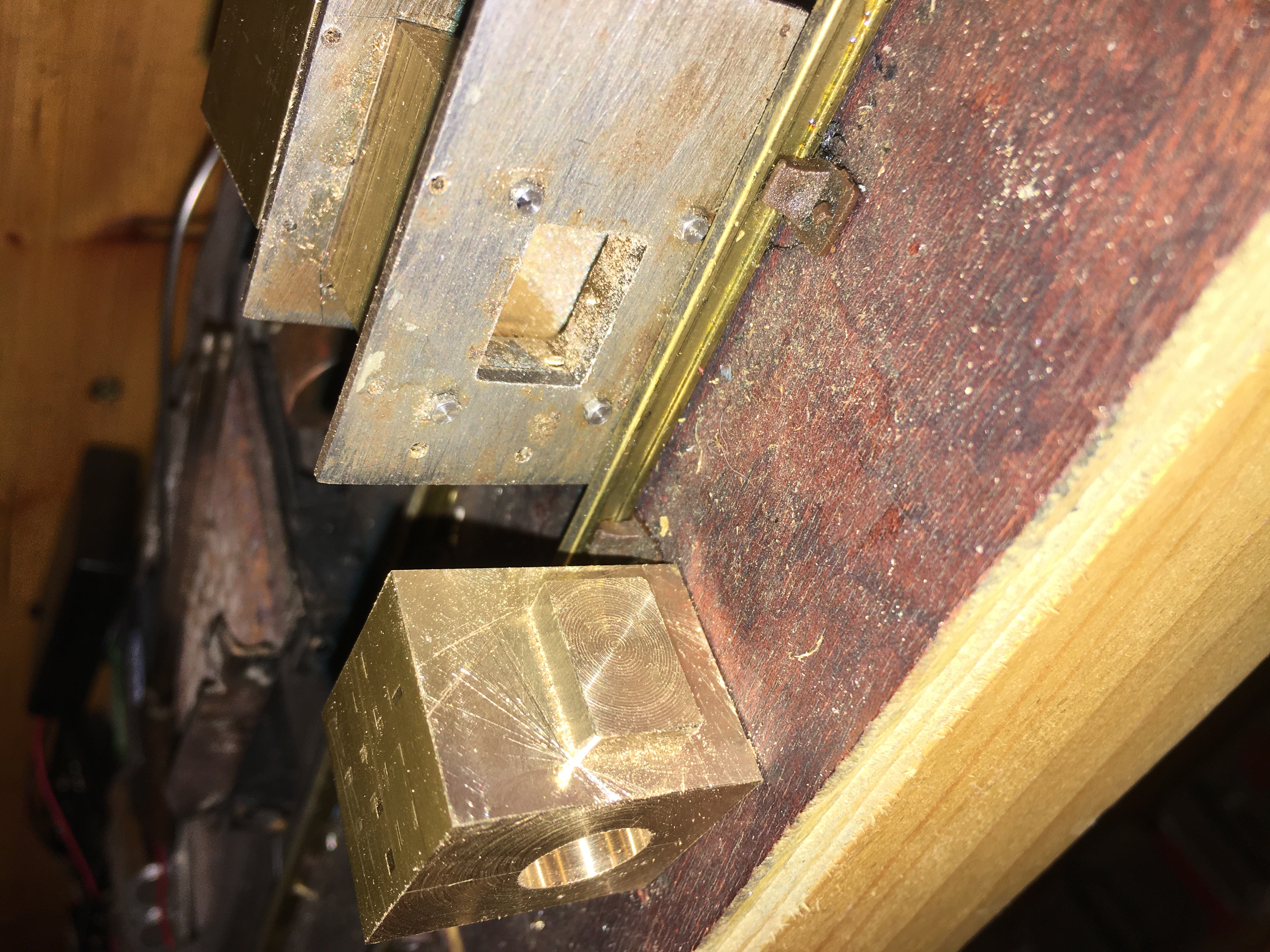
So 4 sections of the block of brass have been parted off in the lathe and turned to size, width, length and height. I have marked the centre of the bores, and bored and reamed them all. Here are two of them:
IMG_2404.JPG
IMG_2404.JPG (1.52 MiB) Viewed 5992 times
I am carrying out each operation on all 4, rather than finishing one and then starting on the next. There is better efficiency in having the machine set up to carry out the operation and having the right tools for doing it to hand, and therefor doing it 4 times.

You might remember from my drawings that the valve face is an extension on the inner face of the cylinder which passes through the frames into the valve chamber. So the first operation was to mill 4.5 mm off that inside face to make the valve face protrude:
IMG_2406.JPG
IMG_2406.JPG (2.61 MiB) Viewed 5992 times
The end result required the sharp edges removing and the opening in the combined valve chamber/frame needed slight filing to get a good sliding fit. This is the first valve face and the hole it fits into:
IMG_2409.JPG
IMG_2409.JPG (3.05 MiB) Viewed 5992 times
The bolt heads holding the frame to the valve chest prevent the cylinder fitting right down to the frame at the moment - and I intend to mill out a pocket in the inside face of the cylinder to swallow the bolt head. I am going to do all the milling first - and then concentrate on drilling afterwards. So here are the 4 cylinders sitting as far into place as they will go at the moment:
IMG_2408.JPG
IMG_2408.JPG (2.87 MiB) Viewed 5992 times
I think it will be milling the bottom of the cylinders to make the flange for the bolts which will hold it to the frame next.

Trevor

Post Reply

Who is online

Users browsing this forum: No registered users and 1 guest