Discussion of Live Steam locomotives should be located here
-
Trevor Thompson
- Trainee Driver

- Posts: 977
- Joined: Fri Oct 05, 2018 6:30 pm
- Location: South West Wales
Post
by Trevor Thompson » Wed Nov 11, 2020 5:35 pm
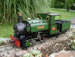
I have been making an attempt at making the injectors on the side of the water tank. I have photos of Linda and I can see that the injectors look nothing like the ones on the drawings for Charles.
It is difficult to make out exactly what and where the pipes actually run. I know how an injector works ( having unsuccessfully tried to make injectors for K1) but that just seems to make the photos more difficult to make out!
So here is my attempt. It doesn't really match the photos but it is a start:
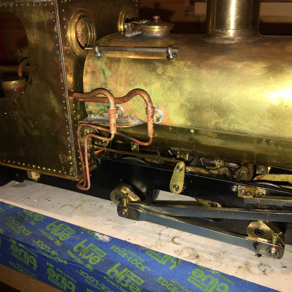
- IMG_1052.jpg (300.82 KiB) Viewed 5827 times
I am sure that you will be able to guide me to better photos - and perhaps even explain what pipes are going where!!!!
Trevor
-
bambuko
- Trainee Fireman

- Posts: 212
- Joined: Tue Dec 12, 2017 12:11 am
- Location: UK, England, North Devon
Post
by bambuko » Wed Nov 11, 2020 5:54 pm
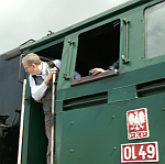
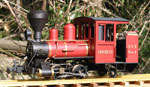
As an inspiration, here is a screen grab from a Youtube video I have linked in one of my previous posts:

- blanche_small.jpg (94.59 KiB) Viewed 5825 times
don't know how good it is and not sure whether he actually uses if functionally? rather than just cosmetically?
and... here, resonable picture of full size thing:
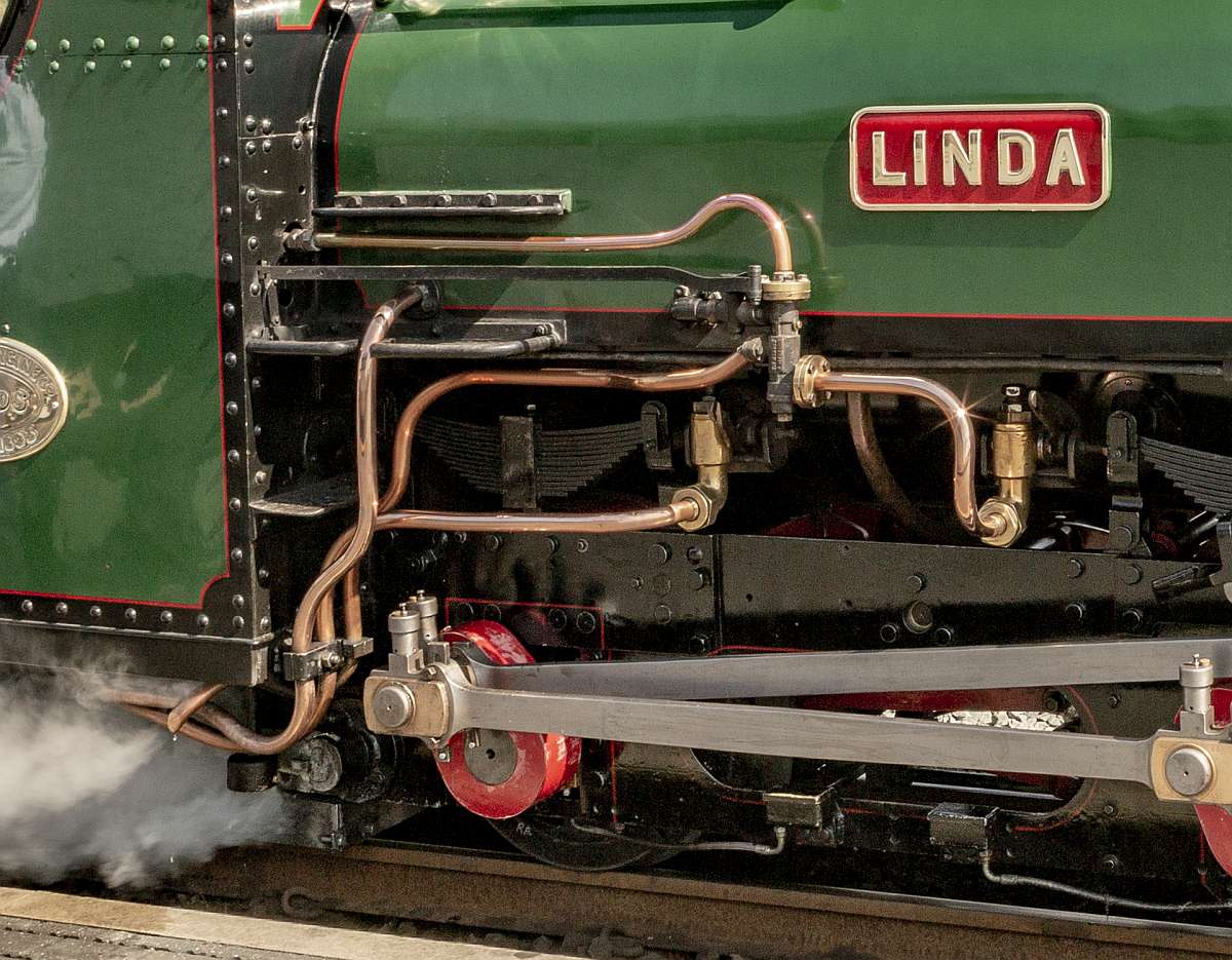
- piping.jpg (173.43 KiB) Viewed 5825 times
Would love if someone knowledgeable explained the whole thing to me as well

Last edited by
bambuko on Wed Nov 11, 2020 6:08 pm, edited 1 time in total.
-
bambuko
- Trainee Fireman
- Posts: 212
- Joined: Tue Dec 12, 2017 12:11 am
- Location: UK, England, North Devon
Post
by bambuko » Wed Nov 11, 2020 6:07 pm
TonyW wrote: ↑Thu Nov 05, 2020 11:14 am
...The tightest curve on the FR main line is Tyler's which, with a radius of 157 feet, works at about 2.5m radius in 16mm/foot scale and larger than the average curve found on most 16mm lines.
I did a bit of 3D CAD modelling to check things, and it would be perfectly feasible to run it on 1.2m (or 4ft) radius.
So not really that extreme? althought I guess something like 1.5m (or 5ft) would be better?
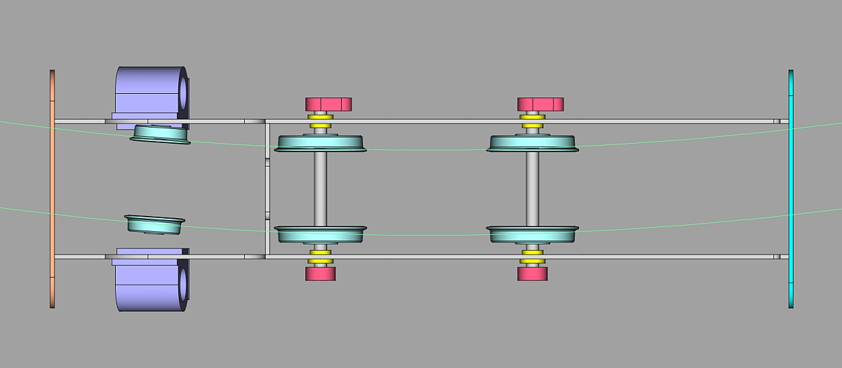
- curve.jpg (77.13 KiB) Viewed 5825 times
I am not suggesting this for Trevor (as I know he hopes to run on tracks with smaller radius), but for anybody else who is reading and would be interested.
Sorry for the thread creep
-
Trevor Thompson
- Trainee Driver
- Posts: 977
- Joined: Fri Oct 05, 2018 6:30 pm
- Location: South West Wales
Post
by Trevor Thompson » Wed Nov 11, 2020 6:17 pm
bambuko wrote: ↑Wed Nov 11, 2020 6:07 pm
TonyW wrote: ↑Thu Nov 05, 2020 11:14 am
...The tightest curve on the FR main line is Tyler's which, with a radius of 157 feet, works at about 2.5m radius in 16mm/foot scale and larger than the average curve found on most 16mm lines.
I did a bit of 3D CAD modelling to check things, and it would be perfectly feasible to run it on 1.2m (or 4ft) radius.
So not really that extreme? althought I guess something like 1.5m (or 5ft) would be better?
curve.jpg
I am not suggesting this for Trevor (as I know he hopes to run on tracks with smaller radius), but for anybody else who is reading and would be interested.
Sorry for the thread creep
That is actually interesting. No need to apologise!
-
TonyW
- Driver

- Posts: 1357
- Joined: Fri May 16, 2008 9:25 am
- Location: North Wales
-
Contact:
Post
by TonyW » Wed Nov 11, 2020 7:29 pm
bambuko wrote: ↑Wed Nov 11, 2020 5:54 pmWould love if someone knowledgeable explained the whole thing to me as well
I might know a bit...
Linda as first converted for FR use:

Basically, still in Penrhyn condition with two injectors mounted on the side of the saddle tank.
Your later/current picture shows only one injector (the front one) still remaining on the tank. The back one has gone and has been replaced by a pipe that runs to a larger injector mounted under the cab floor. By flicking some valves this injector can be fed by either the saddle tank or the tender tank. The small one on the tank side only works off the saddle, not surprisingly.
-
bambuko
- Trainee Fireman
- Posts: 212
- Joined: Tue Dec 12, 2017 12:11 am
- Location: UK, England, North Devon
Post
by bambuko » Wed Nov 11, 2020 7:55 pm
Thank you Tony,
that's very good explanation and helps understanding things a lot

One other thing I have noticed on your photo, is that it seems that in original/Penrhyn condition valve gear lever was on the RH side? (and getting in a way of the piping

).
This is reflected in Keith Bucklitch's plans an both Trevor's and Gandy Dancer's (see youtube link in my earlier post) models.
All the photos I have of both ladies in the later/Ffestiniog condition seem to have moved it to LH side?
-
TonyW
- Driver
- Posts: 1357
- Joined: Fri May 16, 2008 9:25 am
- Location: North Wales
-
Contact:
Post
by TonyW » Wed Nov 11, 2020 8:23 pm
The driving position was swapped from the right to the left-hand side in the 1960s ... putting the injectors under the fireman's control for the first time.
-
Trevor Thompson
- Trainee Driver
- Posts: 977
- Joined: Fri Oct 05, 2018 6:30 pm
- Location: South West Wales
Post
by Trevor Thompson » Wed Nov 11, 2020 9:49 pm
That really explains quite a lot!
I wondered about the driving position and the differences in the reverser gear. I couldn't understand why the plans show the reverser on the right hand side and the photos are the opposite!
Also that explains the injectors. The original situation is as per the drawing for Charles - and I can understand the arrangement (I think). The water comes directly from the tank side. The steam supplies come from the cab where there have to be valves to operate them. The overflows are easy to spot, and the clack valves are in the side of the boiler below the tank.
I might just modify what I have done to fit in with this. Nothing I have made can't be modified!
Thanks
Trevor
-
GTB
- Driver
- Posts: 1559
- Joined: Sat Mar 05, 2011 2:46 pm
- Location: Australia
Post
by GTB » Thu Nov 12, 2020 12:11 pm
Trevor Thompson wrote: ↑Wed Nov 11, 2020 3:59 pm
Maybe it is worth persevering with grub screws, certainly M2.5 sounds attractive - I will have to look to see if I have an M2.5 tap? Probably need to buy one! I am planning a Stephenson valved model of one of the large England engines - so that might be the time to try it.
Sounds like a plan.
Whatever size grub screws you use, lay in a few hex keys as well, as the little ones don't last long in my experience and I can verify that breaking one in a grub screw, or rounding out the socket by using a worn key, ruins your whole day.........

The other thing I found out the hard way is don't use grub screws with silver steel shafts and axles. They don't grip properly, as the silver steel is too hard to penetrate properly. I should have known better, but had run out of round BMS in that size.

Regards,
Graeme
-
GTB
- Driver
- Posts: 1559
- Joined: Sat Mar 05, 2011 2:46 pm
- Location: Australia
Post
by GTB » Thu Nov 12, 2020 12:37 pm
Trevor Thompson wrote: ↑Wed Nov 11, 2020 9:49 pm
Also that explains the injectors. The original situation is as per the drawing for Charles - and I can understand the arrangement (I think). The water comes directly from the tank side. The steam supplies come from the cab where there have to be valves to operate them. The overflows are easy to spot, and the clack valves are in the side of the boiler below the tank.
I was wondering where the water valves were, but close inspection of Tony's photo shows they are part of the fitting where the injectors are connected to the saddle tank. The water control rods can just be seen running back into the cab.
Regards,
Graeme
-
TonyW
- Driver
- Posts: 1357
- Joined: Fri May 16, 2008 9:25 am
- Location: North Wales
-
Contact:
Post
by TonyW » Thu Nov 12, 2020 3:55 pm
At that time, they were standard Hunslet injectors. The water valve is actually part of the injector body and is no more than a taper plug with a cross hole. I won't post an image link but you can see exactly the same type of injector on Lilla here:
https://upload.wikimedia.org/wikipedia/ ... t_2011.jpg
Click on the image to make it bigger.
-
Trevor Thompson
- Trainee Driver
- Posts: 977
- Joined: Fri Oct 05, 2018 6:30 pm
- Location: South West Wales
Post
by Trevor Thompson » Fri Nov 13, 2020 9:00 pm
While I am waiting for some fine copper mesh for a gas filter to arrive I am adding the details. The bits I missed off - while I prioritised getting a working loco. I have modified and remade the dummy injectors and their associated piping. This is a bit more like the prototype:
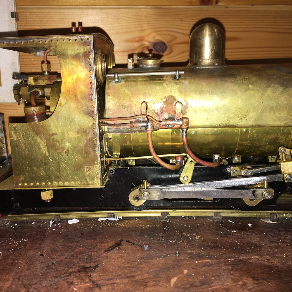
- IMG_1066.jpg (358.38 KiB) Viewed 5538 times
I am going to have to change the reach rod to make it a bit more realistic. The rear injector pipe and clack valve are preventing the reach rod moving properly. Also I think the bit of bent brass rod is flexing as the servo arm moves, resulting in lost travel, and I think that might be why changing from ahead to astern doesn't quite work half of the time. So two reasons to modify it. That is a job for tomorrow!
The only other detail which I know I missed off are the dummy springs. So while I am working in that area I will make springs and fit them. I have four top leaves left over from K1 - so there is a starting point. Instead of the working springs on K1 these will be dummies!
-
Trevor Thompson
- Trainee Driver
- Posts: 977
- Joined: Fri Oct 05, 2018 6:30 pm
- Location: South West Wales
Post
by Trevor Thompson » Fri Nov 13, 2020 9:05 pm
And of course I will have to do something to the cab. That will have to come off to get at the servo and the reach rod. I might as well sort out the spectacle plates - they really are not close enough to the real appearance. They are the result of cutting square holes before I realised the plans for Charles didn't apply to Linda in this area.
I also need to suggest the joint between top and bottom of the cab sides, the rivet detail, and perhaps even an edging for the cab sides.
Trevor
-
Trevor Thompson
- Trainee Driver
- Posts: 977
- Joined: Fri Oct 05, 2018 6:30 pm
- Location: South West Wales
Post
by Trevor Thompson » Sun Nov 15, 2020 6:23 pm
A start on the springs. One spring assembled and another three as blank spring leafs. I made the centre piece by milling some hex rod. Yet to add the rods which on the real thing connect to the chassis. In this case the centre of the spring will be bolted behind the chassis.
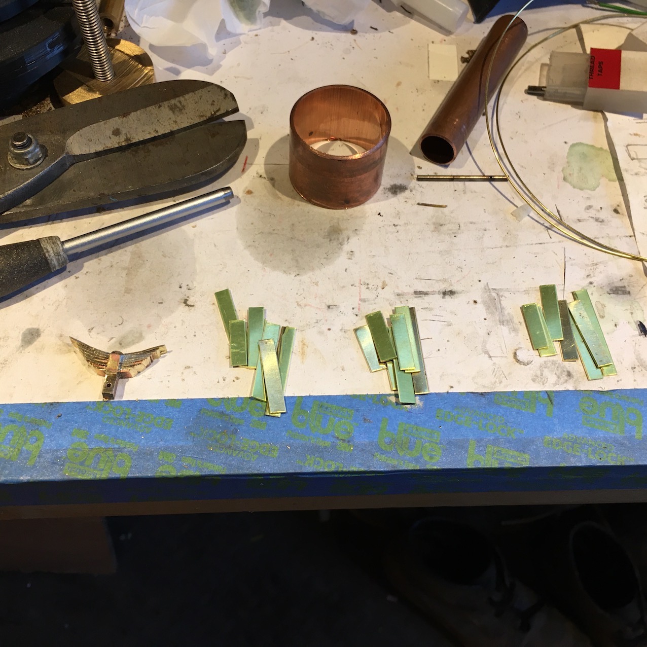
- IMG_1071.jpg (341.04 KiB) Viewed 5497 times
Trevor
-
Trevor Thompson
- Trainee Driver
- Posts: 977
- Joined: Fri Oct 05, 2018 6:30 pm
- Location: South West Wales
Post
by Trevor Thompson » Sun Nov 22, 2020 10:38 pm
I nhave finished making the springs and fitted them, I have also made a new reach rod which is stiffer, to replace the bit of bent wire.
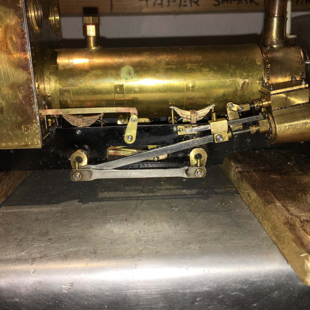
- IMG_1087.jpg (335.41 KiB) Viewed 5395 times
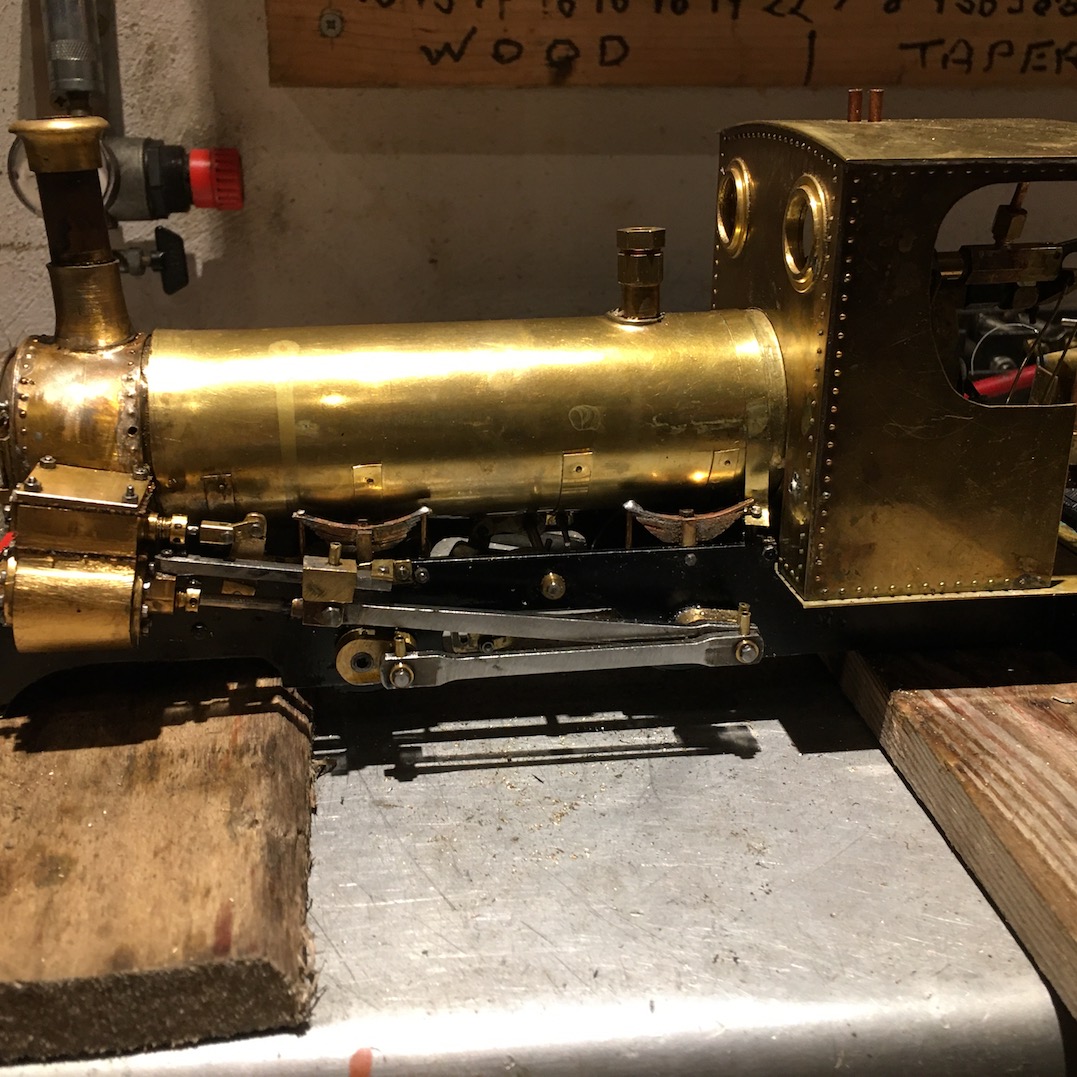
- IMG_1086.jpg (289.73 KiB) Viewed 5395 times
Just the spectacle plate to play with now, and then I will try to get video of it running properly.
Trevor
-
bambuko
- Trainee Fireman
- Posts: 212
- Joined: Tue Dec 12, 2017 12:11 am
- Location: UK, England, North Devon
Post
by bambuko » Mon Nov 23, 2020 3:28 pm
Thanks for the updates Trevor

Looking forward to more videos

One question BTW still not quite clear in my mind (and it is really a question about prototype rather than model) - is the securing of cylinders to the loco frame.
With very high cylinder line above the frames it seems very precarious to fix them just to the frame

unless there is also some fixing of cyliners to the smokebox

Perhaps
TonyW with his inside knowledge of Ffestiniog will be able to enlighten us

-
TonyW
- Driver
- Posts: 1357
- Joined: Fri May 16, 2008 9:25 am
- Location: North Wales
-
Contact:
Post
by TonyW » Mon Nov 23, 2020 4:33 pm
When first built the three locos had their cylinders attached to the frames by a single row of bolts with the upper part of the cylinders being bolted to the smokebox. Working on the FR soon showed up this weakness so Linda and Blanche had a front-end rebuild and now the bottom half of the smokebox is integral with the frames to support the cylinders properly. There is a lot more steel plate in the front end than there used to be!
-
bambuko
- Trainee Fireman
- Posts: 212
- Joined: Tue Dec 12, 2017 12:11 am
- Location: UK, England, North Devon
Post
by bambuko » Mon Nov 23, 2020 4:56 pm
TonyW wrote: ↑Mon Nov 23, 2020 4:33 pm
...bottom half of the smokebox is integral with the frames to support the cylinders properly. There is a lot more steel plate in the front end than there used to be!
Thank you Tony
I suspected something like this was the case, but it is not very clear in any of the photos in my collection

I know this goes beyond the modelling
but I am interested in wider aspects of engineering and design
-
TonyW
- Driver
- Posts: 1357
- Joined: Fri May 16, 2008 9:25 am
- Location: North Wales
-
Contact:
Post
by TonyW » Tue Nov 24, 2020 4:04 pm
Let me put it this way... if the top of the smokebox on Linda or Blanche needs to be removed it has to be cut off with a gas torch, and then welded back in place afterwards. The smokebox base is now a substantial structure and very firmly attached to the chassis. Hence we end up with views like this:

I wasn't around at the time, but this work *may* have happened in the early 1970s when the frames were extended for the pony truck. It certainly would have made sense to do it then.
-
bambuko
- Trainee Fireman
- Posts: 212
- Joined: Tue Dec 12, 2017 12:11 am
- Location: UK, England, North Devon
Post
by bambuko » Tue Nov 24, 2020 7:15 pm
Both the info and attached photo are absolutely brilliant!
thank you Tony
Funny thing is, that I was thinking to myself, that is how I would strengthen things, but dismissed it...
a) because I had no photo evidence that this is what has happened
b) because it seemed silly idea
I guess the photo is from your private collection?
Who is online
Users browsing this forum: No registered users and 8 guests