16mm scale "Linda"
-
- Trainee Driver
- Posts: 977
- Joined: Fri Oct 05, 2018 6:30 pm
- Location: South West Wales
Re: 16mm scale "Linda"
Pivot for the rocker arm:
The rocker arm pin which is tapped 8BA at each end:
the inner rocker arm. It is tapped 8BA and held in place with a nut and pinned as well. If it isn't pinned it will move.:
the outer rocker arm. Again tapped 8BA but no nut. Pin through.
valve link:
The rocker arm pin which is tapped 8BA at each end:
the inner rocker arm. It is tapped 8BA and held in place with a nut and pinned as well. If it isn't pinned it will move.:
the outer rocker arm. Again tapped 8BA but no nut. Pin through.
valve link:
-
- Trainee Driver
- Posts: 977
- Joined: Fri Oct 05, 2018 6:30 pm
- Location: South West Wales
Re: 16mm scale "Linda"
Some notes on the valve gear. All the pivot points are tapped 10BA and pivot on 10BA bolts. Where possible lock with a 10 BA nut. The only exception to that is the rocker arm where both ends are tapped 8BA. Each end will move if it isn't pinned. The outer end is permanent - the inner can be dismantled. I use 10 BA bolts with 11BA heads throughout.
I hope that the dimensions are readable. Having drawn it in sketch I then had difficulty exporting it without catching loads of unwanted dimensions - which is why I ended up with screenshots. If the original sketch file is of use I can post that as well.
Trevor
I hope that the dimensions are readable. Having drawn it in sketch I then had difficulty exporting it without catching loads of unwanted dimensions - which is why I ended up with screenshots. If the original sketch file is of use I can post that as well.
Trevor
- dewintondave
- Trainee Driver
- Posts: 697
- Joined: Mon Mar 07, 2011 8:52 am
- Location: New Zealand
- bambuko
- Trainee Fireman
- Posts: 212
- Joined: Tue Dec 12, 2017 12:11 am
- Location: UK, England, North Devon
Re: 16mm scale "Linda"
It's not just a software. The book is hard read as well.Trevor Thompson wrote: ↑Fri Nov 06, 2020 6:49 pm So I am not the only one who struggled with his software...
Don was extremely knowledgable and very respected but as far as I am concerned the master of the subject doesn't necessarily make the best teacher of it
I am still persevering though - worst part of it is that there is nobody to ask if one has any questions (forum is not the right place for it...)
I personally prefer using prof. Bill Hall's approximate method, followed by Charlie Dockstader's simulator.
There seem to be quite a difference of opinion about merits of axle driven pump.Trevor Thompson wrote: ↑Fri Nov 06, 2020 7:17 pm ---I didn't make the water tank to the drawing - I actually made it so that it had a bottom and would hold water if I decide to fit an axle driven water pump...
I personally like the idea, but think that it has to be carefully designed.
no personal experience, but here is Dick Moger's comments in G1:
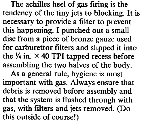
Thank you for posting details of your gear.
With the exception of extension rod, which is a bit challenging (but still usable) all of the drawings attached are perfect.
One immediate question is about eccentric.
I am assuming that 3mm dia hole for axle is not quite what it is in reality?
I will have more deatiled look at it and come back if I have any questions.
BTW - I am assuming that steam and exhaust ports in your design are as per Charles of K. B. ?
-
- Trainee Driver
- Posts: 977
- Joined: Fri Oct 05, 2018 6:30 pm
- Location: South West Wales
Re: 16mm scale "Linda"
Yes the hole in the eccentric might be wrong. I did that from memory (but measured the critical bits).
The rest of the engine is as per the drawings.
Thanks for the info on gas jets blocking. I will have to make a filter.It will have to be very fine though as the No 3 jet has a tiny hole in it.
Trevor
The rest of the engine is as per the drawings.
Thanks for the info on gas jets blocking. I will have to make a filter.It will have to be very fine though as the No 3 jet has a tiny hole in it.
Trevor
-
- Trainee Driver
- Posts: 977
- Joined: Fri Oct 05, 2018 6:30 pm
- Location: South West Wales
Re: 16mm scale "Linda"
Todays progress is limited to making handrails for the tank and firebox.
I make my own handrail knobs:
The first stage is to mount stainless rod 4mm diameter in the chuck and turn down the end and tap it 6BA. I then cut a grove either side of where the ball will be created. Then saw the part free, (it is too small to part off reliably) Repeat 6 times:
Next stage is to set up the rotating table and convert the machine to milling form. Centre for the hole and drill 1.5mm:
and back to the lathe and set each one up in a mandril and file to a ball shape. (To small to use the ball turning tool reliably)
And finally after fitting onto Linda. Holes drilled, tapped and the knobs secured with locktight. The one on the smokebox:
and on the water tank:
- dewintondave
- Trainee Driver
- Posts: 697
- Joined: Mon Mar 07, 2011 8:52 am
- Location: New Zealand
Re: 16mm scale "Linda"
That is beautiful work Trevor! I must continue my Charles project now
Best wishes,
Dave
Dave
- bambuko
- Trainee Fireman
- Posts: 212
- Joined: Tue Dec 12, 2017 12:11 am
- Location: UK, England, North Devon
Re: 16mm scale "Linda"
Hi Trevor, what advance did you use for the eccentric (either angular or linear dimension), please?Trevor Thompson wrote: ↑Sat Nov 07, 2020 9:10 pm The eccentric:
...
The centre for the axle is offset from the centre of the eccentric by 3.5mm.
According to Charles drawings, as designed it has 1/32" steam lap.
-
- Trainee Driver
- Posts: 977
- Joined: Fri Oct 05, 2018 6:30 pm
- Location: South West Wales
Re: 16mm scale "Linda"
The drawings showed 8BA grub screws holding the eccentrics. I adjusted them initially at dead centre. When assembled I adjusted each one until the valves were opening just after dead centre, and closing again after about 75 - 80% of the travel.
A bit crude I know but it seems to have worked.
I think Don Ashton gives a better way, which I will try next time.
I could only get the 8BA grub screws with slotted heads - and they are far too weak. I kept breaking them. So I would certainly lock the eccentrics permanently before assembly next time.
Trevor
- bambuko
- Trainee Fireman
- Posts: 212
- Joined: Tue Dec 12, 2017 12:11 am
- Location: UK, England, North Devon
Re: 16mm scale "Linda"
it's remarkable how forgiving these little steam engines areTrevor Thompson wrote: ↑Tue Nov 10, 2020 1:23 pm ...A bit crude I know but it seems to have worked...
Yes, he does.
Setting (or making them) as a pair is definitely much better than juggling four eccentrics
8BA is equivalent to M2.5 - you can easily get stainless allen key grub screws from ebay in this and other sizes.Trevor Thompson wrote: ↑Tue Nov 10, 2020 1:23 pm ...I could only get the 8BA grub screws with slotted heads - and they are far too weak...
That is, provided you are willing to go metric
for example this is the supplier I use:
grub screw
Re: 16mm scale "Linda"
A bit crude, maybe, but this is pretty much the method Roundhouse advocates for valve-timing on their kit models.Trevor Thompson wrote: ↑Tue Nov 10, 2020 1:23 pm The drawings showed 8BA grub screws holding the eccentrics. I adjusted them initially at dead centre. When assembled I adjusted each one until the valves were opening just after dead centre, and closing again after about 75 - 80% of the travel.
A bit crude I know but it seems to have worked.
Trevor
I must say how glad I am you've decided to start posting about this model. Many of us lack the skill and/or machinery to make a locomotive completely from scratch, and there are several of these in the works right now which is very inspirational. And, this shouldn't be considered a slight towards anyone's building, but the other chaps, well it seems to me that their builds are very polished- which is a good thing- but I especially like this one because you readily admit that sometimes your ideas don't work out, and your locomotive (again I hope not to cause offence) bears the tool-marks from having been made out of pieces of metal hand-worked the old-fashioned way. Which again, isn't necessarily a virtue nor is it a fault, but for me it's just a little easier to appreciate in a way for someone like me who struggles to do a nice job on a Brandbright coach-kit and usually has to do things twice or thrice before they work out. I like to hear about the trial-and -error approach to home engineering, although when it happens to me I struggle to persevere sometimes.
Anyway, I just wanted to register my appreciation for your work, and I'm looking forward to seeing more.
- Hydrostatic Dazza
- Driver
- Posts: 1167
- Joined: Tue Sep 19, 2017 4:17 am
- Location: Brisbane
- Contact:
Re: 16mm scale "Linda"
Bravo
Cheers from Dazza, The Hydrostatic Lubricator
The chances of finding out what’s really going on in the universe are so remote, the only thing to do is hang the sense of it and keep yourself occupied. Douglas Adams
Re: 16mm scale "Linda"
Slotted head grub screws are about as much use as a chocolate teapot in my opinion, much too easy to break off one side of the slot.......Trevor Thompson wrote: ↑Tue Nov 10, 2020 1:23 pm I could only get the 8BA grub screws with slotted heads - and they are far too weak. I kept breaking them. So I would certainly lock the eccentrics permanently before assembly next time.
I've used M3 hex socket grub screws in the eccentrics of the two sets of Stephensons vg that I've scratchbuilt so far and 6BA in the set I rebuilt. I've not had any movement of the eccentrics in service once the vg is set up and the grub screws tightened.
I can drive down the road and buy M3 hex socket grub screws, but I had to import the 6BA ones from the UK, which is why I've now standardized on M3.
Personally I prefer to be able to set each eccentric separately. Prototype eccentrics were keyed to the axle, so the only way to adjust the valve gear was to remove the eccentric rods and get a blacksmith to stretch, or shrink, the rod(s) that needed adjustment. Not for this little black duck........
If you use hex socket grub screws, the key can be also used to sight the eccentric position relative to the crank pin, which makes adjustment fairly easy. A suitably positioned hole drilled in the eccentric straps means adjustments can be made with the valve gear fully erected and the hole can do double duty as an oiling point.
Regards,
Graeme
-
- Trainee Driver
- Posts: 977
- Joined: Fri Oct 05, 2018 6:30 pm
- Location: South West Wales
Re: 16mm scale "Linda"
[/quote]
A bit crude, maybe, but this is pretty much the method Roundhouse advocates for valve-timing on their kit models.
I must say how glad I am you've decided to start posting about this model. Many of us lack the skill and/or machinery to make a locomotive completely from scratch, and there are several of these in the works right now which is very inspirational. And, this shouldn't be considered a slight towards anyone's building, but the other chaps, well it seems to me that their builds are very polished- which is a good thing- but I especially like this one because you readily admit that sometimes your ideas don't work out, and your locomotive (again I hope not to cause offence) bears the tool-marks from having been made out of pieces of metal hand-worked the old-fashioned way. Which again, isn't necessarily a virtue nor is it a fault, but for me it's just a little easier to appreciate in a way for someone like me who struggles to do a nice job on a Brandbright coach-kit and usually has to do things twice or thrice before they work out. I like to hear about the trial-and -error approach to home engineering, although when it happens to me I struggle to persevere sometimes.
Anyway, I just wanted to register my appreciation for your work, and I'm looking forward to seeing more.
[/quote]
Thanks for the kind words. It is good to hear that my input to the website is appreciated.
Trevor
-
- Trainee Driver
- Posts: 977
- Joined: Fri Oct 05, 2018 6:30 pm
- Location: South West Wales
Re: 16mm scale "Linda"
Maybe it is worth persevering with grub screws, certainly M2.5 sounds attractive - I will have to look to see if I have an M2.5 tap? Probably need to buy one! I am planning a Stephenson valved model of one of the large England engines - so that might be the time to try it.
The De Winton has fixed eccentrics - and I hope I have silver soldered them in the correct position! Time will tell.
-
- Trainee Driver
- Posts: 977
- Joined: Fri Oct 05, 2018 6:30 pm
- Location: South West Wales
Re: 16mm scale "Linda"
I have been making an attempt at making the injectors on the side of the water tank. I have photos of Linda and I can see that the injectors look nothing like the ones on the drawings for Charles.
It is difficult to make out exactly what and where the pipes actually run. I know how an injector works ( having unsuccessfully tried to make injectors for K1) but that just seems to make the photos more difficult to make out!
So here is my attempt. It doesn't really match the photos but it is a start:
I am sure that you will be able to guide me to better photos - and perhaps even explain what pipes are going where!!!!
Trevor
- bambuko
- Trainee Fireman
- Posts: 212
- Joined: Tue Dec 12, 2017 12:11 am
- Location: UK, England, North Devon
Re: 16mm scale "Linda"
As an inspiration, here is a screen grab from a Youtube video I have linked in one of my previous posts:
and... here, resonable picture of full size thing: Would love if someone knowledgeable explained the whole thing to me as well
don't know how good it is and not sure whether he actually uses if functionally? rather than just cosmetically?and... here, resonable picture of full size thing: Would love if someone knowledgeable explained the whole thing to me as well
Last edited by bambuko on Wed Nov 11, 2020 6:08 pm, edited 1 time in total.
- bambuko
- Trainee Fireman
- Posts: 212
- Joined: Tue Dec 12, 2017 12:11 am
- Location: UK, England, North Devon
Re: 16mm scale "Linda"
I did a bit of 3D CAD modelling to check things, and it would be perfectly feasible to run it on 1.2m (or 4ft) radius.
So not really that extreme? althought I guess something like 1.5m (or 5ft) would be better?
I am not suggesting this for Trevor (as I know he hopes to run on tracks with smaller radius), but for anybody else who is reading and would be interested.
Sorry for the thread creep
-
- Trainee Driver
- Posts: 977
- Joined: Fri Oct 05, 2018 6:30 pm
- Location: South West Wales
Re: 16mm scale "Linda"
That is actually interesting. No need to apologise!bambuko wrote: ↑Wed Nov 11, 2020 6:07 pmI did a bit of 3D CAD modelling to check things, and it would be perfectly feasible to run it on 1.2m (or 4ft) radius.
So not really that extreme? althought I guess something like 1.5m (or 5ft) would be better?
curve.jpg
I am not suggesting this for Trevor (as I know he hopes to run on tracks with smaller radius), but for anybody else who is reading and would be interested.
Sorry for the thread creep
Re: 16mm scale "Linda"
I might know a bit...
Linda as first converted for FR use:
Basically, still in Penrhyn condition with two injectors mounted on the side of the saddle tank.
Your later/current picture shows only one injector (the front one) still remaining on the tank. The back one has gone and has been replaced by a pipe that runs to a larger injector mounted under the cab floor. By flicking some valves this injector can be fed by either the saddle tank or the tender tank. The small one on the tank side only works off the saddle, not surprisingly.
Tony Willmore
Rhos Helyg Locomotive Works: http://www.rhoshelyg.me.uk
Facebook: https://www.facebook.com/RhosHelygLocoWorks
Rhos Helyg Locomotive Works: http://www.rhoshelyg.me.uk
Facebook: https://www.facebook.com/RhosHelygLocoWorks
Who is online
Users browsing this forum: No registered users and 10 guests