
Thanks Dave, I reckon your a game man soldering a ring that thin and then machining it to fit. Concentricity doesn't have to be far out when you involve the lathe. Congratulations.
Grant.
Wild Rose ~ Quarry Hunslet
-
dewintondave
- Trainee Driver

- Posts: 697
- Joined: Mon Mar 07, 2011 8:52 am
- Location: New Zealand
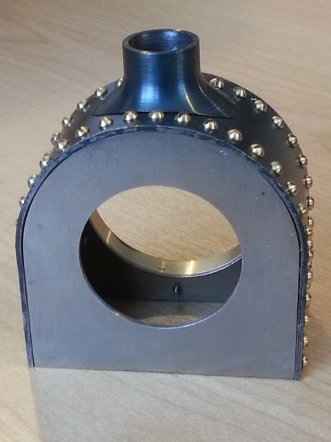
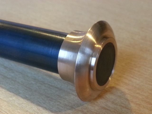
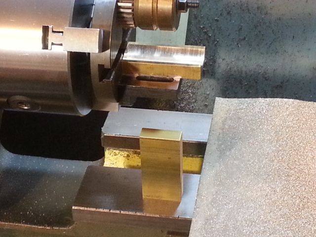
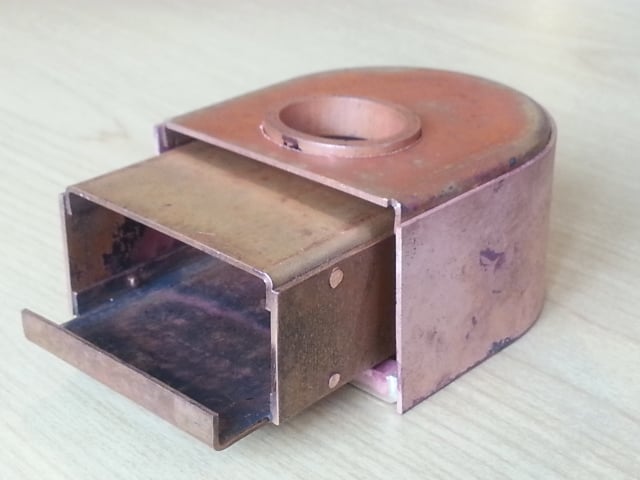
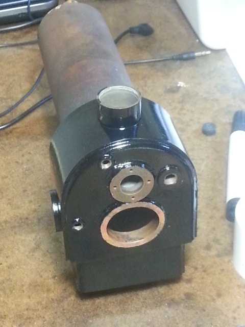
I made the chimney base from steel. One of the first operations was to mill the smokebox profile on its base. I did this in the lathe, with my old Emco Unimat 3 flycutter.
After milling, the blank was turned in the lathe, working both handles to get the large radius.
The job is secured to the mandrel by Loctite 609 retainer
Lots of heat is required to remove the job from the mandrel, the chimney base is now a lovely blue/black colour
After milling, the blank was turned in the lathe, working both handles to get the large radius.
The job is secured to the mandrel by Loctite 609 retainer
Lots of heat is required to remove the job from the mandrel, the chimney base is now a lovely blue/black colour
Last edited by dewintondave on Sun Nov 24, 2019 3:45 am, edited 1 time in total.
Best wishes,
Dave
Dave
-
dewintondave
- Trainee Driver
- Posts: 697
- Joined: Mon Mar 07, 2011 8:52 am
- Location: New Zealand
Thank you Keith!Keith S:118494 wrote:It certainly is a pleasure to see the work in progress. It looks like a fine job so far. I am particularly impressed with the boiler/smokebox flange.
---
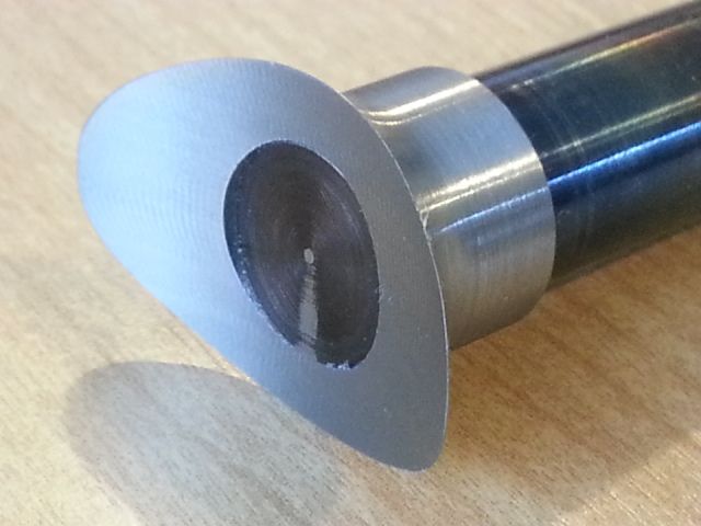
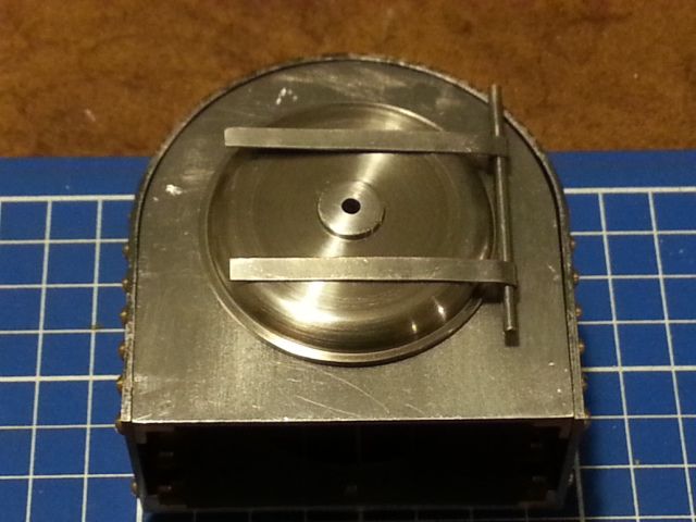
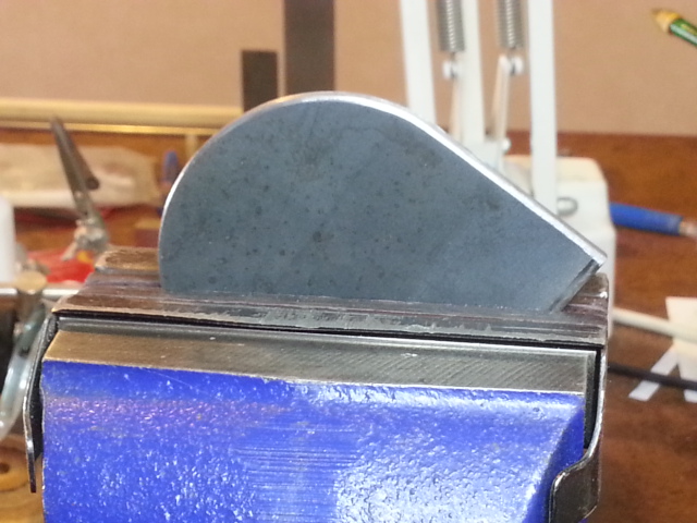
Moving to the other side of the smokebox, the smokebox door. This is made from a slice of free cutting steel soft soldered to a mandrel after the rear face was turned.
Rear face details just visible
Profiling the front face
Finished door still on mandrel
Hinge straps cut out of 0.6mm sheet with tin snips
Finished hinges. I used LBSC's "words and music" for the straps and lugs. I had to borrow the roundhead screws from the live diesel
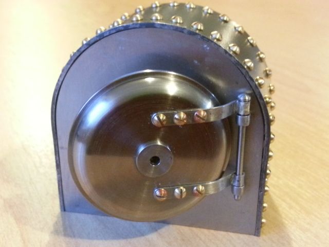
The door is swinging!
Last edited by dewintondave on Sun Nov 24, 2019 3:49 am, edited 1 time in total.
Best wishes,
Dave
Dave

-
dewintondave
- Trainee Driver
- Posts: 697
- Joined: Mon Mar 07, 2011 8:52 am
- Location: New Zealand
Thank you!philipy:118509 wrote:Dave,
The big problem with your work is that I ran out of superlatives long ago! As always, I'm in awe.
Last edited by dewintondave on Sun Nov 24, 2019 3:50 am, edited 1 time in total.
Best wishes,
Dave
Dave
-
dewintondave
- Trainee Driver
- Posts: 697
- Joined: Mon Mar 07, 2011 8:52 am
- Location: New Zealand
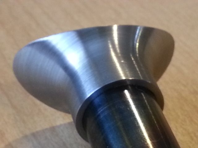
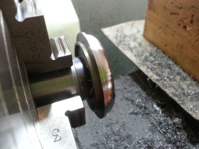
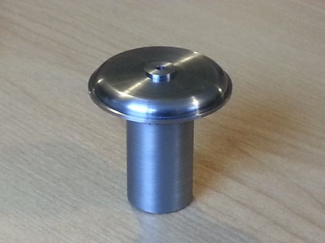
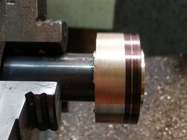
It was time to start on the chimney. I started at the top.
Gunmetal was used for the chimney cap. The blank was Loctited to the mandrel
Marking out the upper curved part
I filed this curved surface
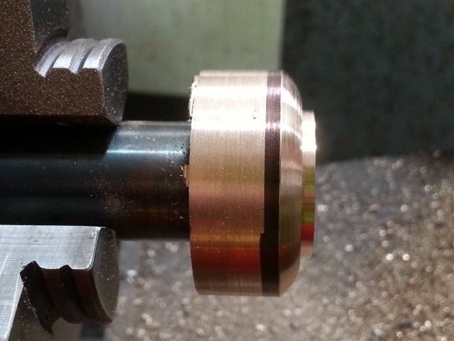
Rough turned
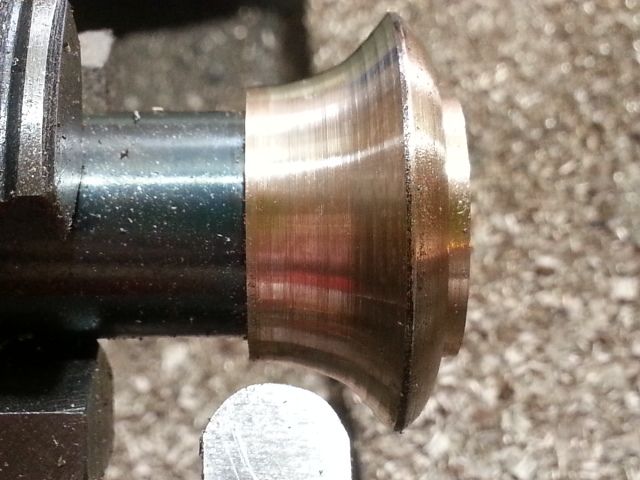
Finish turned
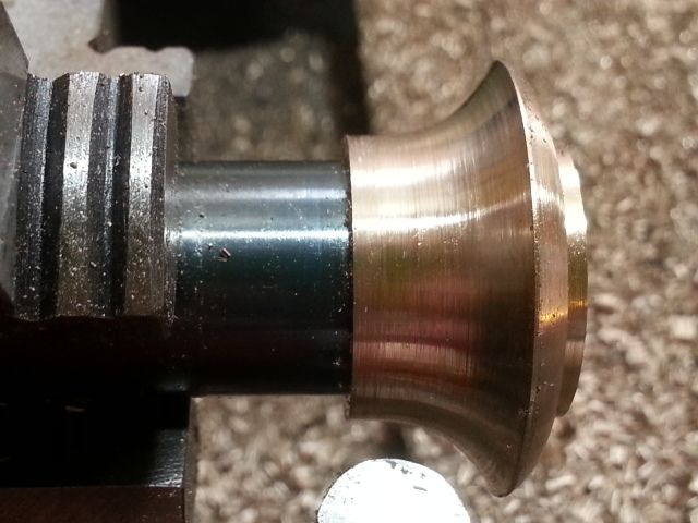
Finished part
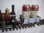
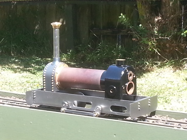
Tall chimney version
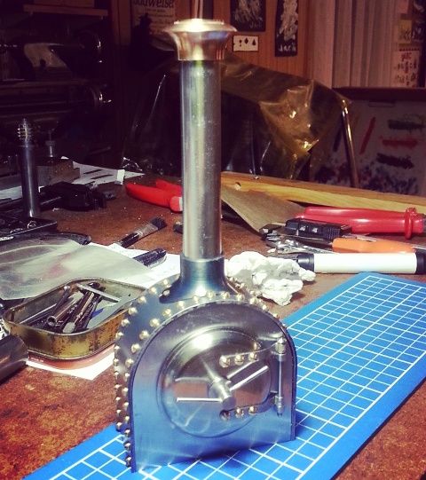
Cross-bar fitted
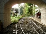
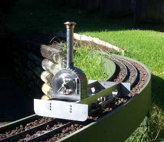
Out on the line!
It was a lovely morning for a cigar and coffee!
Gunmetal was used for the chimney cap. The blank was Loctited to the mandrel
Marking out the upper curved part
I filed this curved surface
Rough turned
Finish turned
Finished part
Tall chimney version
Cross-bar fitted
Out on the line!
It was a lovely morning for a cigar and coffee!
Last edited by dewintondave on Sun Nov 24, 2019 5:51 am, edited 1 time in total.
Best wishes,
Dave
Dave
-
robyholmes
- Cleaner

- Posts: 69
- Joined: Mon Mar 09, 2015 5:22 pm
- Contact:
-
dewintondave
- Trainee Driver
- Posts: 697
- Joined: Mon Mar 07, 2011 8:52 am
- Location: New Zealand
Thank you!robyholmes:118836 wrote:Fantastic! Love seeing your work.
---
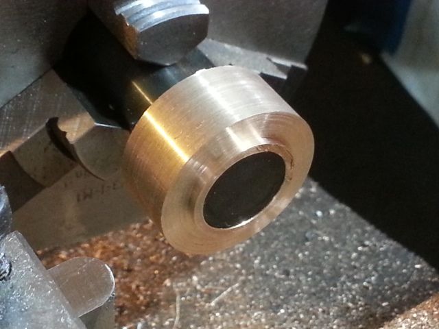
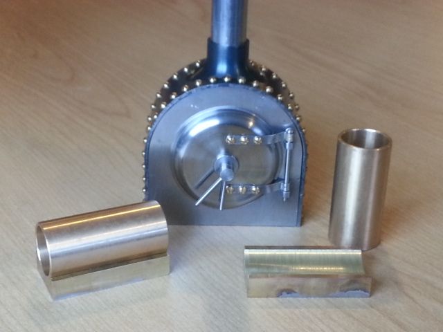
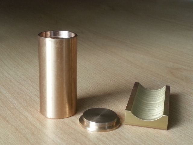
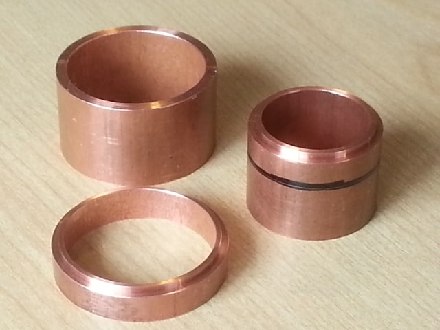
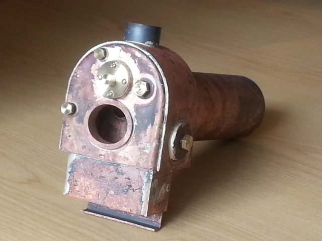
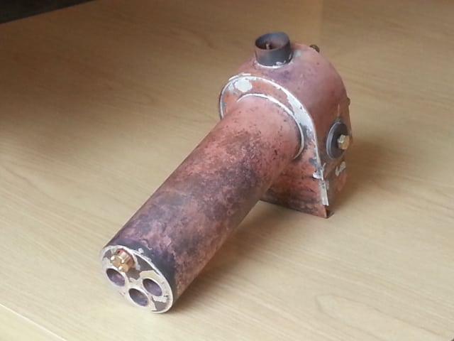
I made a start on the cylinders. I like to use commercial plain bronze bearings for oscillator cylinders. They have a very good surface finish.
The port faces were bored in the lathe using the exact same set-up as was used for my large de Winton. Bored for the cylinders to be able to be soft soldered to them.
The faceplate required counter balance weights

The port face is soft soldered to the faceplate angle plate
I want the rear covers to be removable. I like screwcutting so decided to thread the end covers and the cylinder. An internal tool was ground for the cylinder, this took days... I've used 40 tpi as the pitch. As the threads were short I turned the chuck by hand. My wrist was aching like a teenager's afterwards!
Last edited by dewintondave on Sun Nov 24, 2019 5:53 am, edited 1 time in total.
Best wishes,
Dave
Dave
-
dewintondave
- Trainee Driver
- Posts: 697
- Joined: Mon Mar 07, 2011 8:52 am
- Location: New Zealand
I thought I'd tackle the boiler next so that I could see where everything will go. I've been very slowly progressing.
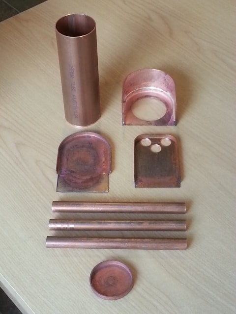
A supply of 1.5 mm copper sheet, 2", and 1/2" copper pipe was already on hand. I've recently received some more sticks of the cadmium free silver solder (brazing rods) from Macc Models, I'm ready to make a sizeable investment in the boiler - lots of silver.
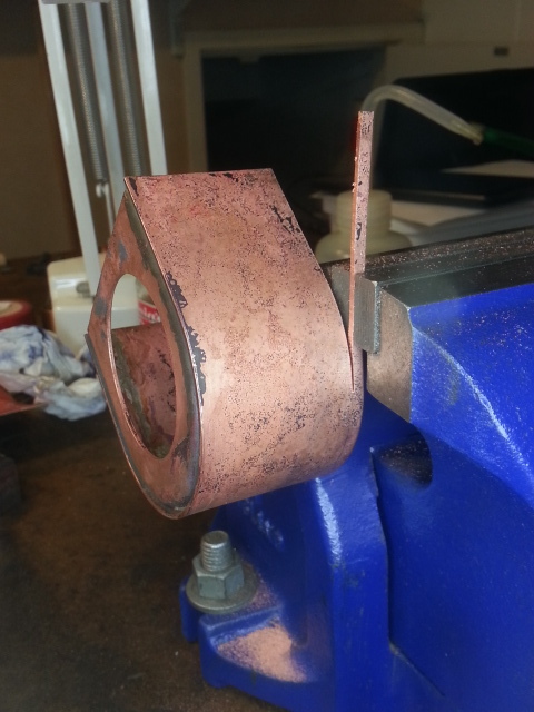
Some 4 mm thick steel was bought to make flanging formers. I was able to reuse a boiler endplate flanging former from my first loco build; the small De Wintons. Flanging is very satisfying with frequent stops for annealing the copper sheet.
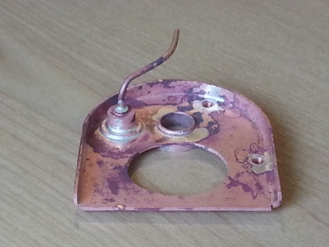
Rounding off the throatplate / backhead former
Rework #1: Removing a thin strip from the wrapper using the piercing saw. The throatplate is already brazed in place.
Backhead and former
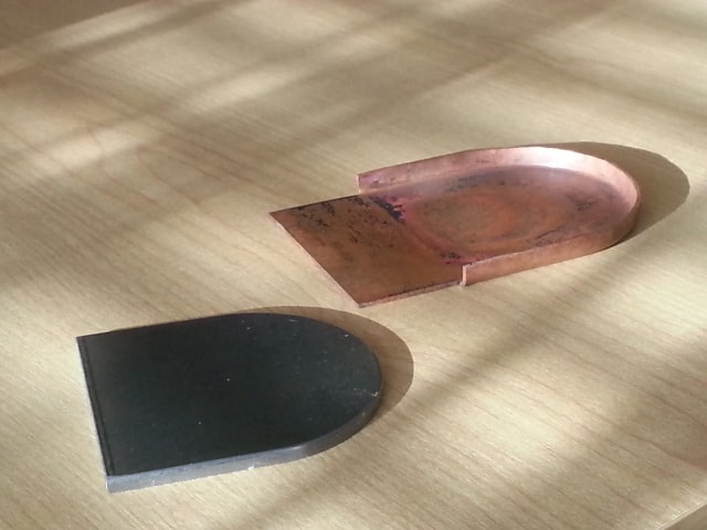
Firebox former with unformed plate
Progress so far
A supply of 1.5 mm copper sheet, 2", and 1/2" copper pipe was already on hand. I've recently received some more sticks of the cadmium free silver solder (brazing rods) from Macc Models, I'm ready to make a sizeable investment in the boiler - lots of silver.
Some 4 mm thick steel was bought to make flanging formers. I was able to reuse a boiler endplate flanging former from my first loco build; the small De Wintons. Flanging is very satisfying with frequent stops for annealing the copper sheet.
Rounding off the throatplate / backhead former
Rework #1: Removing a thin strip from the wrapper using the piercing saw. The throatplate is already brazed in place.
Backhead and former
Firebox former with unformed plate
Progress so far
Last edited by dewintondave on Sun Nov 24, 2019 5:55 am, edited 1 time in total.
Best wishes,
Dave
Dave
-
dewintondave
- Trainee Driver
- Posts: 697
- Joined: Mon Mar 07, 2011 8:52 am
- Location: New Zealand
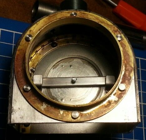
The boiler has been a real mission. I went for the classic wet everywhere firebox, to have at least built one once. Using one grade of silver braze. Doing all the brazing in low-light to keep an eye on not getting the job overheated on subsequent brazing operations. I had to order-in Sievert's excellent Cyclone burners. These are the only burners that can remain alight in the firebox. I'm using the smaller Cyclone burner for steam testing the boiler at the moment.
Trying out different firehole rings. Went with the smaller one, which still gives a generous opening
Dry-run of the Firebox pieces
Firebox inner, pieces riveted together
Firebox Inner with brazing partially complete, with tubes and tubeplate installed for the next brazing operation
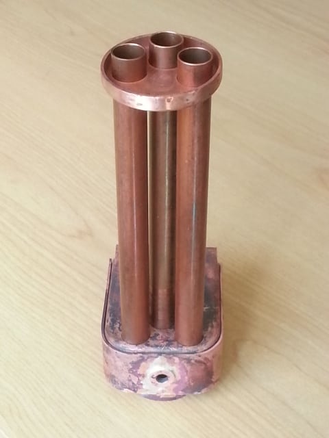
Firebox inner complete, with tubes brazed in
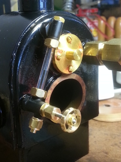
Making bushes for the backhead and trying-out the bought-in "3/16" x 40 tpi plain water gauge" I buy from Macc Models
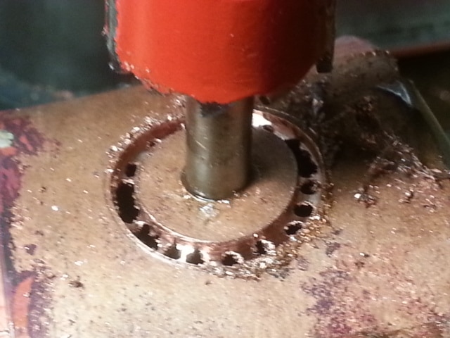
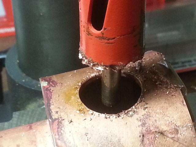
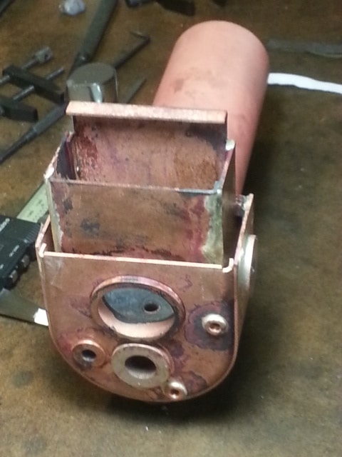
Starting the hole for the turret / dome bush. Using a holesaw with the pilot drill replaced by solid steel rod. This really helped my flimsy bench drill
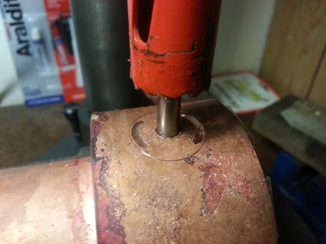
Once the above cut had become continuous it stopped cutting, and I was cautious of a dig-in with all that soft copper. I drilled many holes to break-up the cut, and it was a success.
Finished at last without any drama
Hole needs filing to finished size. Before the drilling, I marked-out the finished size and position
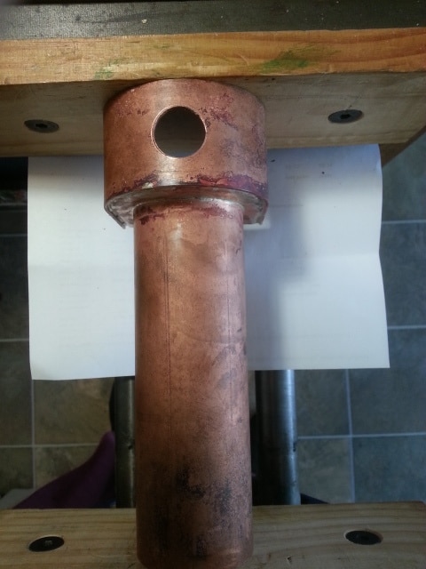
Looking through the tubes
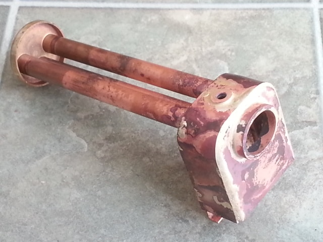
This low sited bush will take the blower valve. A small pipe will draw steam from the dome.
Dry-run of firebox inner and backhead in the boiler shell
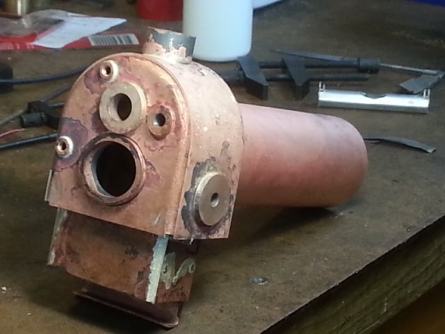
Foundation-ring pieces. The backhead has already been brazed into the boiler shell
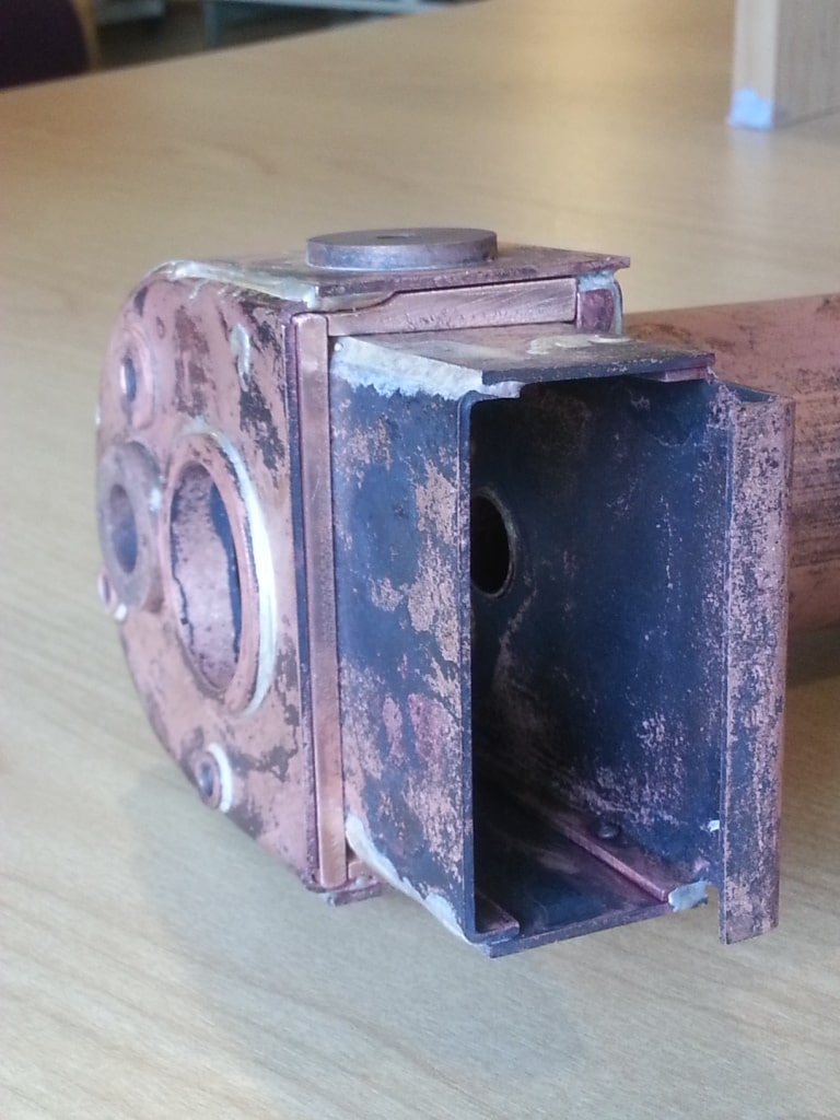
Boiler fully brazed with bushes plugged for testing
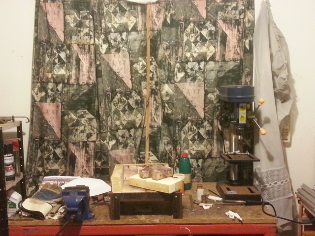
My brazing bench in the garage with window boarded and curtained for daytime brazing sessions
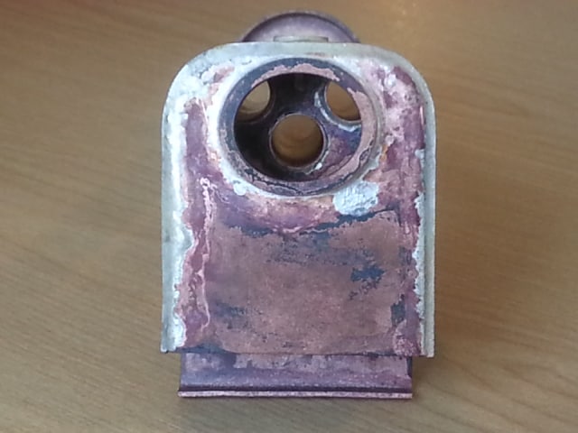
Boiler fully immersed in citric acid pickle bucket
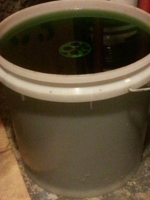
Pretty in pink! I love the natural copper colour
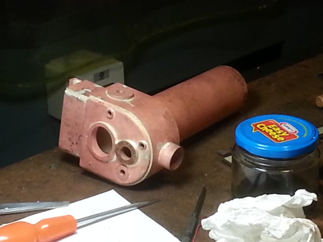
Boiler, full of water, in the fridge. I cooled it all down so that only a little heat would be needed to pressure test the boiler. I use the gentle warming method to expand the water. No pumping required! It's proved to be a controversial method.
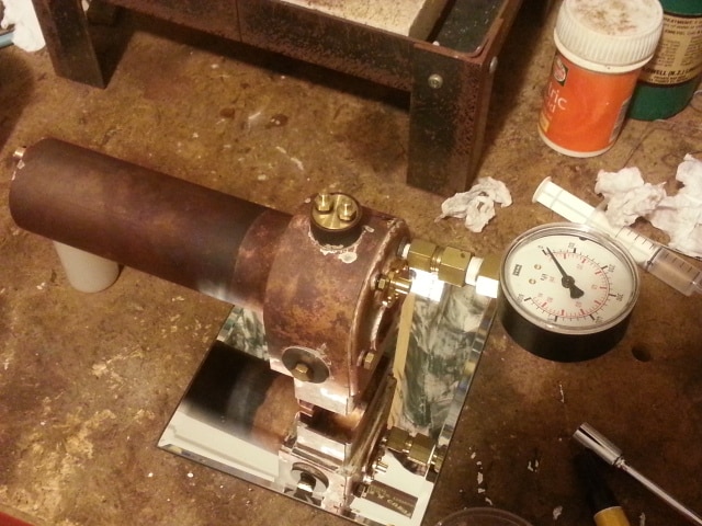
On the garage workbench, ready for testing. Test gauge (0 to 86 PSI) fitted to blower bush.
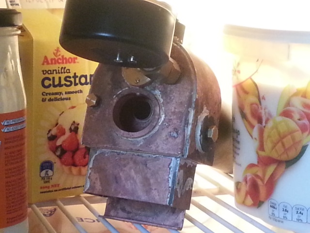
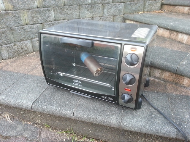
I decided to paint the backhead end to cover a multitude of sins! The fumes were so foul, I took my mini oven outside to bake the Engine Block enamel (rated to 500 deg F). My last baking was at 150 deg C, which is a little above the steam temp at 40 PSI
Finished paint
Out on the railway for the sun
Backhead
Trying out different firehole rings. Went with the smaller one, which still gives a generous opening
Dry-run of the Firebox pieces
Firebox inner, pieces riveted together
Firebox Inner with brazing partially complete, with tubes and tubeplate installed for the next brazing operation
Firebox inner complete, with tubes brazed in
Making bushes for the backhead and trying-out the bought-in "3/16" x 40 tpi plain water gauge" I buy from Macc Models
Starting the hole for the turret / dome bush. Using a holesaw with the pilot drill replaced by solid steel rod. This really helped my flimsy bench drill
Once the above cut had become continuous it stopped cutting, and I was cautious of a dig-in with all that soft copper. I drilled many holes to break-up the cut, and it was a success.
Finished at last without any drama
Hole needs filing to finished size. Before the drilling, I marked-out the finished size and position
Looking through the tubes
This low sited bush will take the blower valve. A small pipe will draw steam from the dome.
Dry-run of firebox inner and backhead in the boiler shell
Foundation-ring pieces. The backhead has already been brazed into the boiler shell
Boiler fully brazed with bushes plugged for testing
My brazing bench in the garage with window boarded and curtained for daytime brazing sessions
Boiler fully immersed in citric acid pickle bucket
Pretty in pink! I love the natural copper colour
Boiler, full of water, in the fridge. I cooled it all down so that only a little heat would be needed to pressure test the boiler. I use the gentle warming method to expand the water. No pumping required! It's proved to be a controversial method.
On the garage workbench, ready for testing. Test gauge (0 to 86 PSI) fitted to blower bush.
I decided to paint the backhead end to cover a multitude of sins! The fumes were so foul, I took my mini oven outside to bake the Engine Block enamel (rated to 500 deg F). My last baking was at 150 deg C, which is a little above the steam temp at 40 PSI
Finished paint
Out on the railway for the sun
Backhead
Last edited by dewintondave on Sun Nov 24, 2019 6:08 am, edited 1 time in total.
Best wishes,
Dave
Dave
Hi Dave, fantastic work as usual. I could feel the tension using the hole saw to cut that dome hole (I would be very ready to reverse the handle on the drill feed). What will be the approx. size of the grate? you've certainly got enough tube area for what appears to be a very short grate. A freshly built boiler always looks great after pickling, and yours is no exception.
I think your "contraversial" boiler test method comes about from some thinking you have to boil the water before any pressure increase, no understanding of basic hydraulics.
Glad your boiler passed its test.
Grant.
I think your "contraversial" boiler test method comes about from some thinking you have to boil the water before any pressure increase, no understanding of basic hydraulics.
Glad your boiler passed its test.
Grant.
-
dewintondave
- Trainee Driver
- Posts: 697
- Joined: Mon Mar 07, 2011 8:52 am
- Location: New Zealand
Thanks Grant. The only support it had was the backhead Sellotaped onLNR:122612 wrote:Hi Dave, fantastic work as usual. I could feel the tension using the hole saw to cut that dome hole (I would be very ready to reverse the handle on the drill feed).
The grate's about 1" x 2.5"
Might as well have an as easy steaming boiler as possible
Last edited by dewintondave on Sun Nov 24, 2019 6:09 am, edited 1 time in total.
Best wishes,
Dave
Dave
-
tom_tom_go

- Driver

- Posts: 4824
- Joined: Wed Feb 23, 2011 3:08 am
- Location: Kent, UK
- Contact:
-
dewintondave
- Trainee Driver
- Posts: 697
- Joined: Mon Mar 07, 2011 8:52 am
- Location: New Zealand
Two weren't enough. I did the math, and wanted something on the upper end of the usual acceptable ratio. It was a while ago now.tom_tom_go:122614 wrote:Thanks for sharing the build with us all so far Dave, you make it look so easy to build!
Can I ask why you have gone for three tubes? Your design is similar to the Riverdale boiler I have which only has two.
Best wishes,
Dave
-
dewintondave
- Trainee Driver
- Posts: 697
- Joined: Mon Mar 07, 2011 8:52 am
- Location: New Zealand
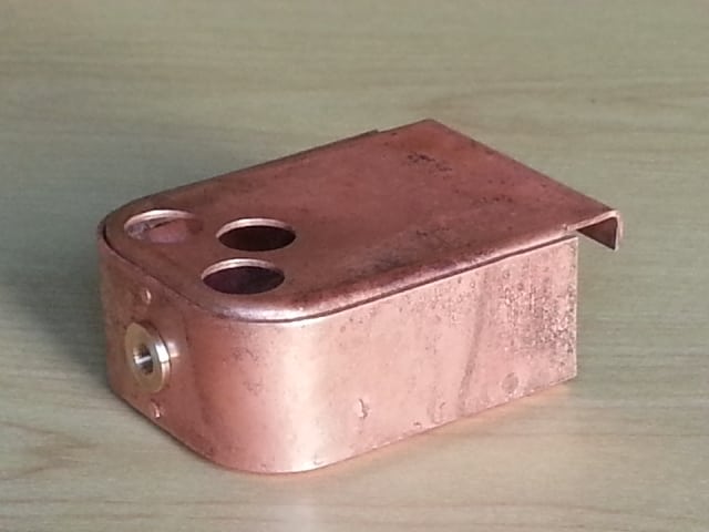
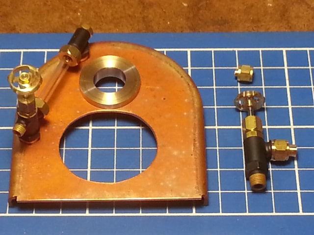
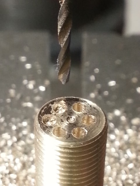
As the test pressure gauge was still attached to the boiler I thought I'd make the safety valve next. It's the ball bearing type, but not a pop-valve.
This is the top of the safety valve, the holes were marked out and centre punched under my bench mounted illuminated magnifying glass, and drilled in the bench drill. The holes are 1.3 mm dia.
Testing the safety valve, using the small Sievert cyclone burner
This is the top of the safety valve, the holes were marked out and centre punched under my bench mounted illuminated magnifying glass, and drilled in the bench drill. The holes are 1.3 mm dia.
Testing the safety valve, using the small Sievert cyclone burner
Last edited by dewintondave on Sun Nov 24, 2019 6:19 am, edited 1 time in total.
Best wishes,
Dave
Dave
-
dewintondave
- Trainee Driver
- Posts: 697
- Joined: Mon Mar 07, 2011 8:52 am
- Location: New Zealand
Re: Wild Rose ~ Quarry Hunslet
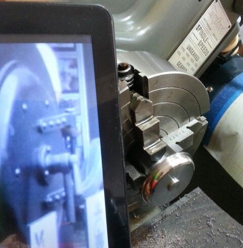
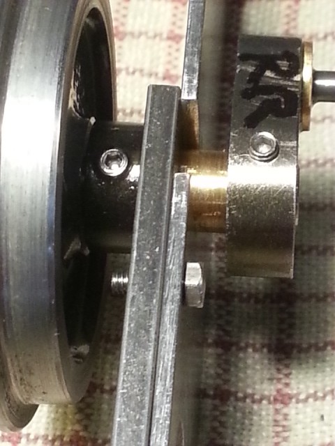
I have been slowly plodding along with the construction, it's been a lot of fun though. At the moment I'm pushing for a steam test soon. The chassis is on the workbench, I'm getting it all set right, I love all the fitting. There was too much sideways play in the axles so I added grubscrews to the spacers that sit between the wheels and axle bushes, these allowed me to adjust their position to reduce play. Then I had the bright idea of oil blackening these parts. They came out a lovely shiny black.
This is the part being blackened in the video
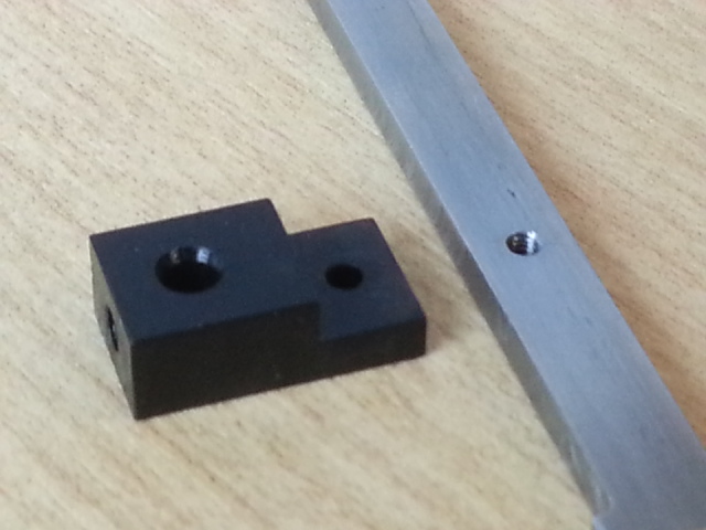
Axle spacer fitted with grub screws
Happy New Year
This is the part being blackened in the video
Axle spacer fitted with grub screws
Happy New Year
Last edited by dewintondave on Sun Nov 24, 2019 6:33 am, edited 1 time in total.
Best wishes,
Dave
Dave
Re: Wild Rose ~ Quarry Hunslet
Hi Dave, Happy New year to you too.
Your blackening process is one I've used for things, but never found it very durable. Some actually chipped off. Have you any experience of this?
Grant.
Your blackening process is one I've used for things, but never found it very durable. Some actually chipped off. Have you any experience of this?
Grant.
-
tom_tom_go
- Driver
- Posts: 4824
- Joined: Wed Feb 23, 2011 3:08 am
- Location: Kent, UK
- Contact:
-
dewintondave
- Trainee Driver
- Posts: 697
- Joined: Mon Mar 07, 2011 8:52 am
- Location: New Zealand
Re: Wild Rose ~ Quarry Hunslet
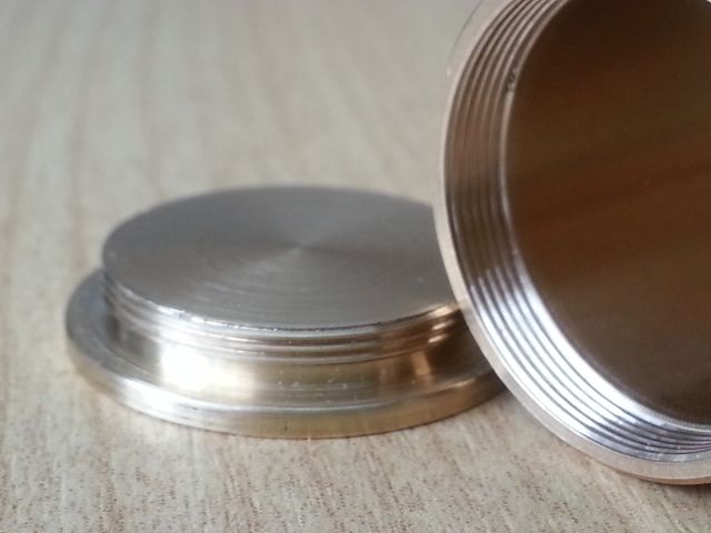
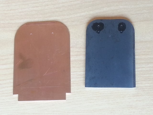
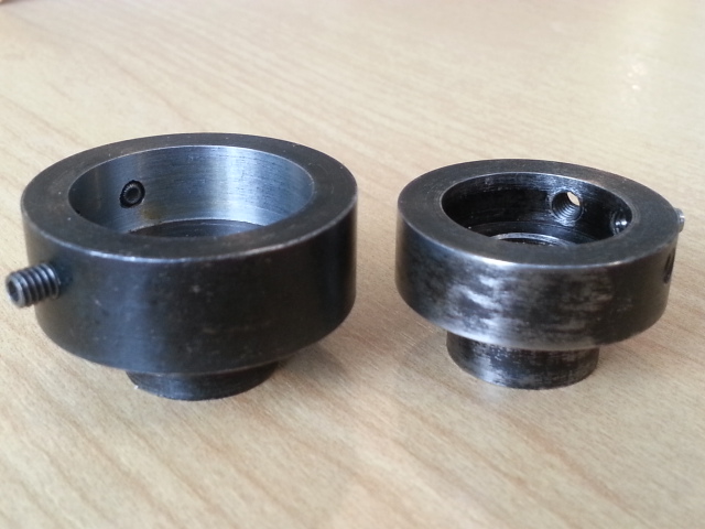
Hi Grant, I've used it a bit. Look at this image, I made these die holders for my Unimat 3 lathe in about 1990, not sure when I blackened them but maybe when I restarted the hobby in 2005. The smaller has worn because I hand thread with it often. I'd say it was an ideal finish for loco parts with no great thickness and no chipping.
Last edited by dewintondave on Sun Nov 24, 2019 6:20 am, edited 1 time in total.
Best wishes,
Dave
Dave
Who is online
Users browsing this forum: No registered users and 7 guests