Couplings

Do you have a problem? Here is the place to appeal for help
User avatar
ge_rik
Administrator
Administrator
Posts: 6554
Joined: Sun Oct 25, 2009 10:20 pm
Location: Cheshire
Contact:

Re: Couplings

Post by ge_rik » Sun Jul 29, 2018 7:17 am

tom_tom_go wrote: Tue May 15, 2018 11:59 am They look better Rik.

Chemically blackening requires the metal is be clean (I normally go over with wet and dry paper).

Don't dunk the metal in the solution, use a brush and do several attempts cleaning the metal each time with water.
Hi Tom
Out of interest and curiosity, I dunked a coupling and a buffer into the fluid and the results are much much better. Presumably, repeated dunking will eventually alter the chemical composition of the fluid - is that the reason for advocating application by brush?

Rik
------------------------
Peckforton Light Railway - Blog Facebook Youtube

User avatar
tom_tom_go
Driver
Driver
Posts: 4824
Joined: Wed Feb 23, 2011 3:08 am
Location: Kent, UK
Contact:

Re: Couplings

Post by tom_tom_go » Sun Jul 29, 2018 8:04 am

I decant a small quantity into a jar and keep it until it stops being effective so to keep the original solution in it's pure form.

Repeated brushing and rinshing in water is effective because it's a gradual attack of the chemcial. You noticed when you just dunked it in the solution the colour would flake off (this can also happen if the part is dirty).

User avatar
ge_rik
Administrator
Administrator
Posts: 6554
Joined: Sun Oct 25, 2009 10:20 pm
Location: Cheshire
Contact:

Re: Couplings

Post by ge_rik » Sun Jul 29, 2018 11:48 am

tom_tom_go wrote: Sun Jul 29, 2018 8:04 am I decant a small quantity into a jar and keep it until it stops being effective so to keep the original solution in it's pure form.

Repeated brushing and rinshing in water is effective because it's a gradual attack of the chemcial. You noticed when you just dunked it in the solution the colour would flake off (this can also happen if the part is dirty).
Thanks Tom
I'll try decanting some.
Rik
------------------------
Peckforton Light Railway - Blog Facebook Youtube

User avatar
ge_rik
Administrator
Administrator
Posts: 6554
Joined: Sun Oct 25, 2009 10:20 pm
Location: Cheshire
Contact:

Re: Couplings

Post by ge_rik » Sun Aug 05, 2018 11:21 am

Slowly progressing with replacing couplings with my version. However, I worked out that the buffers on the bogie coaches would have to be widened to cover 3/4 of the buffer beam if they needed to be propelled over my R2 (Trainline) crossover. I therefore decided to attach the buffers to the bogies as well as the hooks and loops.
IMG_8318.JPG
IMG_8318.JPG (144.81 KiB) Viewed 6137 times
.
As can be seen, the buffers continue to be in contact with each other through the crossover.
IMG_8322.JPG
IMG_8322.JPG (139.6 KiB) Viewed 6137 times
.
Not sure if there is a precedent for this on narrow gauge railways. Be interested if anyone knows how the couplings on bogie stock are made to negotiate tight reverse curves on the real thing.

Rik
------------------------
Peckforton Light Railway - Blog Facebook Youtube

User avatar
IanC
Trainee Driver
Trainee Driver
Posts: 798
Joined: Mon Feb 15, 2016 9:15 am
Location: Nr. Warrington, Cheshire

Re: Couplings

Post by IanC » Sun Aug 05, 2018 11:45 am

On the "real thing" the couplings are attached to the chassis or drawbar. To facilitate tight curves they are in a horizontal slot and pivoted. This allows the bogie to travel freely and guide and support the coach as intended. In our smaller scales this is not too important unless particularly bad trackwork is encountered in which case derailment can occur.

Ian
Ian

User avatar
philipy
Moderator
Moderator
Posts: 5078
Joined: Sun Jan 30, 2011 3:00 pm
Location: South Northants

Re: Couplings

Post by philipy » Fri Aug 10, 2018 11:14 am

Rik,
Having just acquired some 2nd hand coaches in need of some refurbishment, I'm contemplating experimenting with your couplings at the same time. What gauge wire are you using, it's difficult to judge from the photo's?
Philip

User avatar
ge_rik
Administrator
Administrator
Posts: 6554
Joined: Sun Oct 25, 2009 10:20 pm
Location: Cheshire
Contact:

Re: Couplings

Post by ge_rik » Fri Aug 10, 2018 2:13 pm

philipy wrote: Fri Aug 10, 2018 11:14 am Rik,
Having just acquired some 2nd hand coaches in need of some refurbishment, I'm contemplating experimenting with your couplings at the same time. What gauge wire are you using, it's difficult to judge from the photo's?
Hi Philip
For the loops, I'm using 1.5mm brass rod. For the hooks I'm using 22SWG (0.711mm) phosphor bronze wire from Eileen's Emporium - https://eileensemporium.com/index.php?o ... thway=1036

If you're doing a direct replacement for LGB or HLW couplings then these are the dimensions I work to for the bracket (0.7mm thick brass sheet).
Coupling dims.jpg
Coupling dims.jpg (64.81 KiB) Viewed 5963 times
I've made simple wooden jigs for bending the loops and soldering the loops to the brackets.

Let me know if you want any further info.

Rik
------------------------
Peckforton Light Railway - Blog Facebook Youtube

User avatar
philipy
Moderator
Moderator
Posts: 5078
Joined: Sun Jan 30, 2011 3:00 pm
Location: South Northants

Re: Couplings

Post by philipy » Fri Aug 10, 2018 3:09 pm

Thanks Rik.
Philip

User avatar
ge_rik
Administrator
Administrator
Posts: 6554
Joined: Sun Oct 25, 2009 10:20 pm
Location: Cheshire
Contact:

Re: Couplings

Post by ge_rik » Thu Aug 23, 2018 12:39 pm

Well, after a bit of head-scratching and some experimentation, I have achieved my objective of creating a hook-and-loop coupling with delayed action uncoupling. However, I'm not sure how practicable it is (more later).

The loops are as before but the hook has been modified to include a forwards facing larger hook behind the normal hook. I'll call this the "delay latch".
IMG_8395.JPG
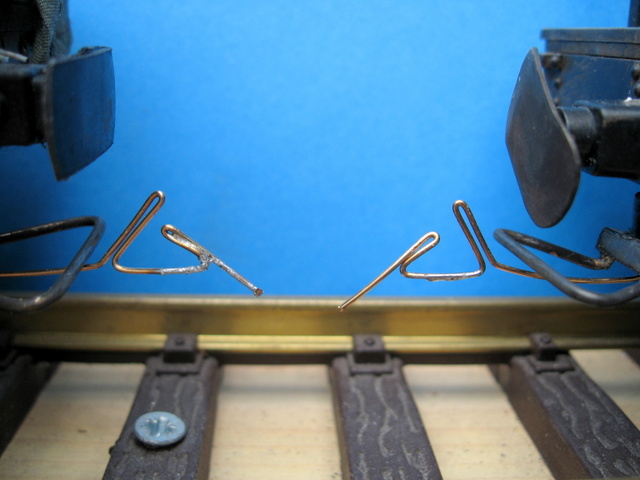
IMG_8395.JPG (94.96 KiB) Viewed 5875 times
.
The coupling hooks couple-up in the usual way. Push one or both wagons together ......
IMG_8395-labelled.jpg
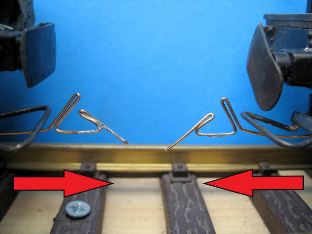
IMG_8395-labelled.jpg (63.13 KiB) Viewed 5875 times
.
... and the hooks latch on to the loops and away we go.
IMG_8397-labelled.jpg
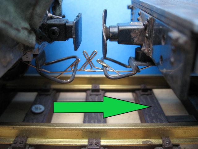
IMG_8397-labelled.jpg (74.63 KiB) Viewed 5875 times
.
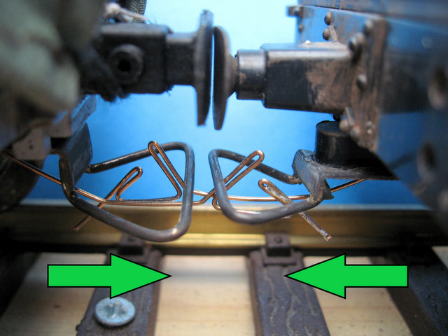
To uncouple, the wagons are propelled backwards (or one is propelled backwards and the other is stationary).
IMG_8398-labelled.jpg
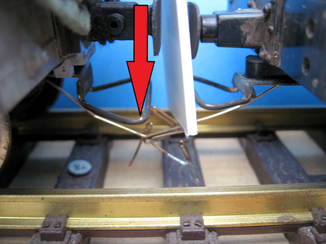
IMG_8398-labelled.jpg (77.09 KiB) Viewed 5875 times
.
The couplings are then pushed downwards to disengage the hooks from the loops. At the same time, the 'delay latches' on the hooks force the wagons apart slightly as they meet the loop on the other wagon.
IMG_8399-labelled.jpg
IMG_8399-labelled.jpg (74.57 KiB) Viewed 5875 times
.
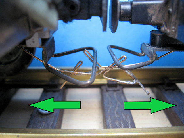
The uncoupler is removed and the wagons continue to be propelled backwards. The delay latches are now the other side of the loops on the opposite wagons.
IMG_8401-labelled.jpg
IMG_8401-labelled.jpg (74.61 KiB) Viewed 5875 times
.
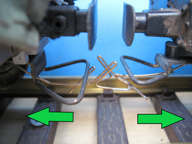
When the wagons are pulled apart (or one is stationary and the other is pulled away from it), the delay latches slide under the loops, .......
IMG_8402-labelled.jpg
IMG_8402-labelled.jpg (72.32 KiB) Viewed 5875 times
.
...... preventing the coupling hooks re-engaging with the loops.
IMG_8403-labelled.jpg
IMG_8403-labelled.jpg (72.64 KiB) Viewed 5875 times
.
Thus the wagons are uncoupled when they are pulled apart at any point after they have been uncoupled.
IMG_8404-labelled.jpg
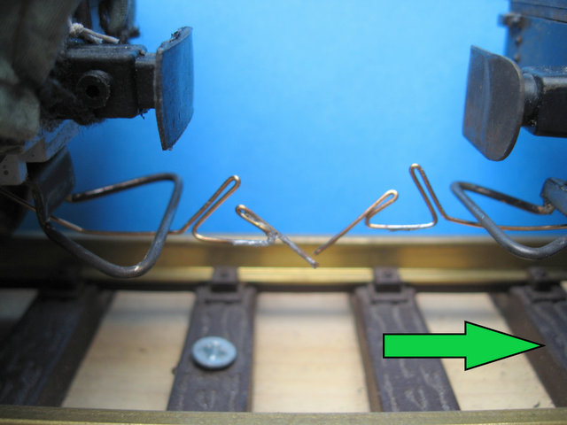
IMG_8404-labelled.jpg (58.14 KiB) Viewed 5875 times
.
I have tried using magnets to do the uncoupling by soldering steel droppers to the underside of the hooks. However, I've not found magnets which are sufficiently strong to pull the hooks down and keep them held down while the delay latches come into force. I might need longer magnets.

Whilst all this is fine in theory, in reality, it's tricky getting the delay latches to work reliably. If the wagon being uncoupled is too light when the hooks are depressed the wagon springs away under the pressure from the delay latches and then when the propelling is continued the coupling hooks re-engage. If the wagon to be uncoupled is too heavy (eg if there are several other wagons behind it), then it's difficult to push the hooks down as the delay latches have to force the wagons apart slightly to work.

So theoretically, the delay latches are a workable concept - but in practice they are not really viable. If I could get the delay latches to hinge upwards somehow and then drop down again to cover the hook then it would work - but it will make the hooks too complicated to construct and might end up interfering with the coupling and uncoupling process.

So - I'll stick with the status quo - ie uncoupling wagons at each location where I want them to remain.

Rik
------------------------
Peckforton Light Railway - Blog Facebook Youtube

User avatar
philipy
Moderator
Moderator
Posts: 5078
Joined: Sun Jan 30, 2011 3:00 pm
Location: South Northants

Re: Couplings

Post by philipy » Thu Aug 23, 2018 1:43 pm

Fascinating Rik.
Interestingly, I've been playing around with the same problem on and off for the last couple of weeks and I just logged on to make a post on the subject and where I've got to with it, only to find this update of yours!

I'm starting a new thread just for info, since I've not really cracked it and I don't want to hijac yours and cause confusion.
Philip

User avatar
GTB
Driver
Driver
Posts: 1559
Joined: Sat Mar 05, 2011 2:46 pm
Location: Australia

Re: Couplings

Post by GTB » Thu Aug 23, 2018 2:36 pm

ge_rik wrote: Thu Aug 23, 2018 12:39 pm So theoretically, the delay latches are a workable concept - but in practice they are not really viable. If I could get the delay latches to hinge upwards somehow and then drop down again to cover the hook then it would work - but it will make the hooks too complicated to construct and might end up interfering with the coupling and uncoupling process.
You've come to the same conclusion I did when I had a think about this a couple of weeks ago.

Blame LGB......... If they'd used the original LaNal coupler ala Tri-ang, instead of an inverted version, delayed uncoupling would be easy to implement.

I've seen Tri-ang couplers modified with a simple swinginging wire ring that can drop down behind the bar when wagons are buffered up with the hooks raised. They can then be pushed into position and when the loco reverses, the ring swings over and covers the hook, allowing it to ride over the bar.

I imagine the reason LGB inverted their coupler was so it could operate under the centre buffers common in Continental NG practice. You could turn your couplers over I guess, so the delay latch could work by gravity, but then you'd need different buffing arrangements.

Regards,
Graeme

User avatar
tom_tom_go
Driver
Driver
Posts: 4824
Joined: Wed Feb 23, 2011 3:08 am
Location: Kent, UK
Contact:

Re: Couplings

Post by tom_tom_go » Thu Aug 23, 2018 3:29 pm

I remember spending months perfecting my uncoupling so I can appreciate the effort you have put in Rik.

User avatar
ge_rik
Administrator
Administrator
Posts: 6554
Joined: Sun Oct 25, 2009 10:20 pm
Location: Cheshire
Contact:

Re: Couplings

Post by ge_rik » Thu Aug 23, 2018 3:36 pm

GTB wrote: Thu Aug 23, 2018 2:36 pm.

I've seen Tri-ang couplers modified with a simple swinginging wire ring that can drop down behind the bar when wagons are buffered up with the hooks raised. They can then be pushed into position and when the loco reverses, the ring swings over and covers the hook, allowing it to ride over the bar.

I imagine the reason LGB inverted their coupler was so it could operate under the centre buffers common in Continental NG practice. You could turn your couplers over I guess, so the delay latch could work by gravity, but then you'd need different buffing arrangements.

Regards,
Graeme
Hi Graeme
It would be relatively easy to modify my hooks so they operated as per Triang tension-locks. I'm trying to visualise how the ring you mention operates. Any chance of a sketch?

Rik
------------------------
Peckforton Light Railway - Blog Facebook Youtube

User avatar
philipy
Moderator
Moderator
Posts: 5078
Joined: Sun Jan 30, 2011 3:00 pm
Location: South Northants

Re: Couplings

Post by philipy » Thu Aug 23, 2018 5:38 pm

ge_rik wrote: Thu Aug 23, 2018 3:36 pm
It would be relatively easy to modify my hooks so they operated as per Triang tension-locks. I'm trying to visualise how the ring you mention operates. Any chance of a sketch?

Rik
Rik,
It would be simple to make a downward facing hook, as you say, but to operate by a magnet below, you'd need a pivot so that the downward force is applied behind the fulcrum, to lift the hook. That's effectively what I tried to do and although it works, it is much more complicated to manufacture than a simple spring wire.

I'll be interested to see the ring device too, because I can't picture it either.
Philip

User avatar
BorisSpencer
Fireman
Fireman
Posts: 251
Joined: Thu Apr 05, 2018 2:36 pm
Location: East Northants

Re: Couplings

Post by BorisSpencer » Thu Aug 23, 2018 6:11 pm

With the tiny neodymium magnets available, you could mount one on the bottom of your couplings and use the repulsion of similar poles to push the coupling up. Obviously it would depend on all the magnets being mounted in the same orientation, but I suspect the repulsive force of two neodymium magnets is considerably stronger than the attractive force of one magnet and a steel wire, it would also be far more focused.

User avatar
ge_rik
Administrator
Administrator
Posts: 6554
Joined: Sun Oct 25, 2009 10:20 pm
Location: Cheshire
Contact:

Re: Couplings

Post by ge_rik » Fri Aug 24, 2018 8:25 am

On refelection, I've decided delayed uncoupling is actually an unnecessary complication, particularly if I used magnets for uncoupling. I'd have to use an electromagnet or a permanent magnet on a movable platform so it would only uncouple the required wagons.

I reckon I could get away with steel droppers on my 'ordinary' couplings and then place permanent magnets at relevant places in my sidings. The attractive power required to release the coupling is far less for the non delay coupling than the delay versions. As with Triang tension locks, I could pull the couplings over the magnets without them uncoupling and then release the tension over the magnet on the coupling needing to be uncoupled.

Sounds like I've just committed myself to a bit more experimentation..... :?

Rik
------------------------
Peckforton Light Railway - Blog Facebook Youtube

User avatar
tom_tom_go
Driver
Driver
Posts: 4824
Joined: Wed Feb 23, 2011 3:08 am
Location: Kent, UK
Contact:

Re: Couplings

Post by tom_tom_go » Fri Aug 24, 2018 11:41 am

If you are going to play about with tension lock couplers you could use an uncoupling ramp?


I did this for a while but then got the magnets working the way I wanted.

User avatar
GTB
Driver
Driver
Posts: 1559
Joined: Sat Mar 05, 2011 2:46 pm
Location: Australia

Re: Couplings

Post by GTB » Thu Aug 30, 2018 4:58 am

ge_rik wrote: Thu Aug 23, 2018 3:36 pm It would be relatively easy to modify my hooks so they operated as per Triang tension-locks. I'm trying to visualise how the ring you mention operates. Any chance of a sketch?
Hi Rik,

Sorry it took so long to reply. The annual AMRA model railway show was on over the weekend and I was otherwise occupied. I still can't find the article I was looking for, so you are stuck with one of my Etch-a-Sketch drawings........

Tri-ang delayed coupler.jpg
Tri-ang delayed coupler.jpg (73.51 KiB) Viewed 3282 times

(1) is the type of hook used by Tri-ang in the '60s. The Mk.III 'Tension Lock', so beloved of 4mm scale modellers.
(2) shows the hook drilled, the wire ring fitted and the back of the hook cut back at an angle. Which must have been fun with the coupler riveted in place on the model........
(3) shows the position of the ring when the couplers are pushed together away from a ramp.
(4) shows the hook in position if the couplers are pushed together with the hooks raised by a ramp. When pushed into position then the loco reversed away, the ring allows the hook to ride ove the loop. Cutting the back of the hook at an angle is important, otherwise it will snag.
(5) shows another Tri-ang coupler mod that allows a sprung wire to be used for uncoupling, instead of a ramp. The wire is a lot less visible, improving cosmetic track appearance, but harder to see for actual operation.

It might give you some ideas. I can't see how it would work with LGB inverted style hooks, as the ring that allows delayed uncoupling relies on gravity to operate.

Regards,
Graeme

User avatar
ge_rik
Administrator
Administrator
Posts: 6554
Joined: Sun Oct 25, 2009 10:20 pm
Location: Cheshire
Contact:

Re: Couplings

Post by ge_rik » Thu Aug 30, 2018 7:59 am

Thanks Graeme. It does mirror what I had in mind for my LGB replacements - a hinged flap which lies against the hook which is pushed up by the bar when coupling and drops back. Is lifted by the bar when uncoupling and drops back to cover the hook to prevent recoupling. It could work by gravity but would have to be very carefully designed and manufactured - which would make my simple bodged system more complicated than my skills and workshop permit.
Delay coupling.jpg
Delay coupling.jpg (262.87 KiB) Viewed 3268 times
.
Rik
------------------------
Peckforton Light Railway - Blog Facebook Youtube

Harris0169
Cleaner
Cleaner
Posts: 15
Joined: Sun Sep 02, 2018 8:39 pm

Re: Couplings

Post by Harris0169 » Thu Sep 06, 2018 10:10 pm

Here is something I saved from the ngrail forum which possibly doesn't exist now? It's by the make of Portpyn.

Here's some extracts of text... I hope Christopher doesn't mind me posting this...The advanced uncoupling article used hooks at both ends...

I have just posted to the "Files" section the relevant drawings. These
were part of my article on the subject published in British Railway
Modelling, April 1995, and are I imagine self explanatory.

The original idea for this type of modification was not mine. I found
it in an ancient copy of RM -

D. R. Mensford: "Advance Uncoupling", RM, March 1969

- and decided to make it single ended (no reverse loops or turntables)
so that each item of rolling stock had only the hook and delay latch
on one end and the modified bar on the other. Whether D. R. Mensford
actually used the system I do not know, and have never seen any other
reference to it or am I aware of its use by others.

Couplings are, I think, a matter of personal choice depending on how
much you want appearance or performance. Being an avowed opponent of
the intrusive "hand of God" style of operation I think performance is
the prevailing criterion. I have found the modified tension locks to
have various advantages as follows.

1. Uncoupling can be achieved by simple sprung ramps as sold by Hornby
or Peco. I prefer the latter. Such ramps can also be easily made from
springy plastic such as is often used in a variety of types of
packaging of household goods.

2. It is fairly robust and experience shows it can stand up to the
rigours of being transported to and from exhibitions.

3. I tend to build most of my rolling stock (and for that matter
locomotives) on cheap (and often second hand) Hornby chassis on which
the coupling comes at the correct height for operation and so as to
speak "for free". Hornby products (new and second hand) are widely
available here in the UK.

4. My stock is freelance inspired by UK or continental European
prototypes, and I imagine it to be fitted with one of the variants of
the "Norwegian chopper" centre buffer and coupling. The Hornby type is
vaguely reminiscent of this style.

5. In operation the modified tension lock functions very much like a
Kadee – stop over the ramp, disengage, pull away by say 10mm, reverse
to push decoupled wagon as far as required.

In all now I have been using modified tension locks for well over a
decade on my exhibition layouts ("St Pierre et la rue Perrin" 1:34e
and "Sutton Wharf" 1:25) with continuing success. I won't claim that
the system is 100%, but it is close to it.


Best wishes

Christopher Payne UK


portpyn coupling.jpg
portpyn coupling.jpg (399.22 KiB) Viewed 3170 times

Post Reply

Who is online

Users browsing this forum: No registered users and 4 guests