Project Raspberry
-
invicta280
- Trainee Driver

- Posts: 664
- Joined: Wed Sep 21, 2011 9:24 pm
- Location: kent england
-
Dr. Bond of the DVLR

- Retired Director

- Posts: 4485
- Joined: Tue Jun 09, 2009 9:43 pm
- Location: Suffolk
- Contact:
We've been rather busy down at Snape Street Works. River Deben is nearly all fitted up now with the nessesary equipment. I think its worked out reasonably neat considering the very large amount of pipework necessary! She is due for a stratford works overhaul and will, at some point, be receiving full GER blue (inc. wheels) with lining. The cab shape is similar to an early GER tank loco, the westinghouse is on the correct side for GER locos.
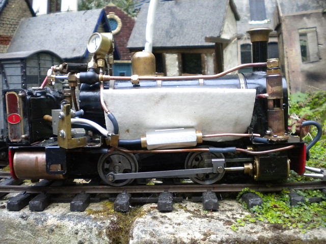
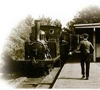
An over view - obvious is the steam feed pipe for the compressor.

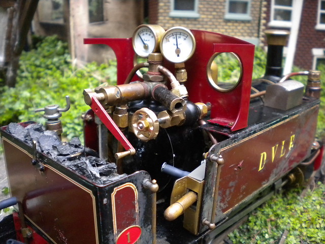
The new cab layout - I've still got to fit a whistle valve in somewhere - the pressure gauges will, eventually, be fitted to a small wooden board against the spectacle plate. The new valve is the steam supply to the pump.
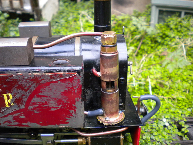
Here's the pump all plumbed in, from top to bottom: Steam feed, Steam exhaust, compressed air out. There is a tiny hole in the bottom which is the air inlet.
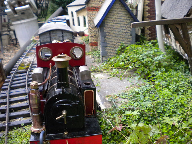
The new view from the front. Oh I love a-symetry!
]
A little view at the gubbins. The white is insulation from the firebox. From top to bottom the horizontal pipes are, roughly:
Steam feed to pump.
Resevoir line - the pump feeds directly into the reservoir (at the back under the cab) via a large propriety Non return valve (they are better than any I could make and a seal is critical)
Brake line - this connects the brake standards fore and aft of the loco. The driver's brake handle lets some air out of the res into the brake line in the "OFF" position. In the "LAP" position everything is sealed. In the "ON" position the brake line evacuates to atmosphere and the res line is sealed.
So there we are. Project raspberry is nearly, after nearly 9 years of experimentation, complete.
An over view - obvious is the steam feed pipe for the compressor.
The new cab layout - I've still got to fit a whistle valve in somewhere - the pressure gauges will, eventually, be fitted to a small wooden board against the spectacle plate. The new valve is the steam supply to the pump.
Here's the pump all plumbed in, from top to bottom: Steam feed, Steam exhaust, compressed air out. There is a tiny hole in the bottom which is the air inlet.
The new view from the front. Oh I love a-symetry!
]
A little view at the gubbins. The white is insulation from the firebox. From top to bottom the horizontal pipes are, roughly:
Steam feed to pump.
Resevoir line - the pump feeds directly into the reservoir (at the back under the cab) via a large propriety Non return valve (they are better than any I could make and a seal is critical)
Brake line - this connects the brake standards fore and aft of the loco. The driver's brake handle lets some air out of the res into the brake line in the "OFF" position. In the "LAP" position everything is sealed. In the "ON" position the brake line evacuates to atmosphere and the res line is sealed.
So there we are. Project raspberry is nearly, after nearly 9 years of experimentation, complete.

The railway which people forgot
(to build)

Who is online
Users browsing this forum: No registered users and 9 guests