Page 1 of 2
Point lever
Posted: Sun Oct 21, 2018 7:39 pm
by ge_rik
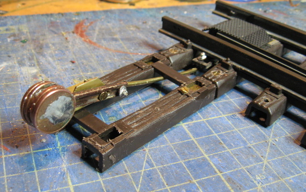
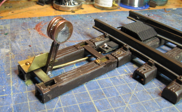
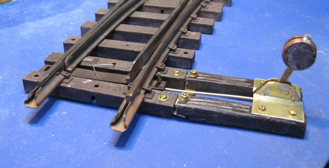
Having just installed some new sidings on the layout - and being particularly dissatisfied with LGB point levers, I decided to have a go at manufacturing my own. A couple of LGB sleepers, a piece of brass sheet, a piece of brass rod, a short length of Peco rail and €0.04, a few nuts and bolts, a bit of solder and the occasional swear word et voila!
- IMG_8843-001.JPG (138.36 KiB) Viewed 7690 times
.
- IMG_8842-001.JPG (148.27 KiB) Viewed 7690 times
.

- IMG_8840.JPG (156.72 KiB) Viewed 7690 times
.

- IMG_8839.JPG (162.56 KiB) Viewed 7690 times
.
I appreciate that it's a bit rough and ready at the moment - this is the prototype. Hopefully Mk2 will look a bit prettier.
Rik
Re: Point lever
Posted: Sun Oct 21, 2018 8:06 pm
by tom_tom_go
It looks perfectly narrow gauge to me!
Re: Point lever
Posted: Sun Oct 21, 2018 8:54 pm
by Clockwork
Rik I’m sure MK2 will be a lot more tidier but I like what you have modelled with the prototype.

Re: Point lever
Posted: Mon Oct 22, 2018 8:53 am
by pandsrowe
It may be be a bit rough and ready but that's what development is all about, I must say you never cease to amaze me with your new projects some of which seem to appear overnight. One thing does puzzle me though, is there a reason for the angular movement of the lever? In one direction it seems to be around 20 degrees and in the other the lever is nearly horizontal, or is this just part of the prototype development in which case I'll shut up.
Re: Point lever
Posted: Mon Oct 22, 2018 9:18 am
by Lonsdaler
Defacing coins of the realm? A capital crime, Surely?

Very nice work Rik

Re: Point lever
Posted: Mon Oct 22, 2018 9:27 am
by ge_rik
pandsrowe wrote: ↑Mon Oct 22, 2018 8:53 am
........ One thing does puzzle me though, is there a reason for the angular movement of the lever? In one direction it seems to be around 20 degrees and in the other the lever is nearly horizontal, or is this just part of the prototype development in which case I'll shut up.
I need to work on the geometry of the linkage. The link at the base of the arm is restricted in one direction but not in the other, so that asymmetric movement was the only way I could get the full throw on the blades. I've figured a way to get a longer throw in both directions, so mk2 should be more evenly balanced.
I also need to fiddle with the mass of the balance weight. Ideally, I'd like sufficient for it to hold the blades in place, but no too much that the flanges can't pass through from the tail of the point - like the real thing.
Rik
Re: Point lever
Posted: Mon Oct 22, 2018 9:33 am
by ge_rik
Lonsdaler wrote: ↑Mon Oct 22, 2018 9:18 am
Defacing coins of the realm? A capital crime, Surely?
Ah but which realms? I noticed that one cent sported an Irish harp, but not sure about the decoration on the others. This version made use of the odds and ends I had knocking about; some 14mm dia brass rod is on order for balance weight on the next version(s).
Perhaps I should be hoarding my Euros .......
Rik
Re: Point lever
Posted: Mon Oct 22, 2018 9:40 am
by ge_rik
pandsrowe wrote: ↑Mon Oct 22, 2018 8:53 am
......... your new projects some of which seem to appear overnight........
Funny you should say that. This one occurred between mowing the grass and tea time (phase 1) - and then between washing-up and watching the last part of serial on TV at 9.00pm (phase 2)

The planning happened during the lawn-mowing, when I picked up a couple of discarded sleepers left over from recent tracklaying ...... an Aha!! moment.
Rik
Re: Point lever
Posted: Mon Oct 22, 2018 3:26 pm
by IrishPeter
I know what you mean by 'Aha moments,' though the original garden railway started with my wife having one. Her's was 'small house with a big garden equals model railway outside.' So they can be dangerous...
I like the lever. It looks a lot like the old WDLR throws, which I suspect were a Hudson design in origin. I have occasionally felt like having a go at the spinning top design the Isle of Man Railway used before it was gentrified in the noughties, which would be the most appropriate levers for the Skebawn and Castleknox.
Cheers,
Peter in Va
Re: Point lever
Posted: Mon Oct 22, 2018 4:12 pm
by GTB
ge_rik wrote: ↑Mon Oct 22, 2018 9:27 am
I also need to fiddle with the mass of the balance weight. Ideally, I'd like sufficient for it to hold the blades in place, but no too much that the flanges can't pass through from the tail of the point - like the real thing.
I'll be interested to see how you go with making the point blades trailable.
One of the turnouts on my planned triangular junction won't be easily accessible when the bridge is in place. I've been contemplating how to make it trailable so I don't have to install a remote lever, but haven't cut metal yet.
Regards,
Graeme
Re: Point lever
Posted: Mon Oct 22, 2018 4:47 pm
by tom_tom_go
Graeme, does the point you are installing need to reset the same way each time? If so, just use a spring or a piece of wire to allow it to reset each time.
Re: Point lever
Posted: Mon Oct 22, 2018 6:00 pm
by ge_rik
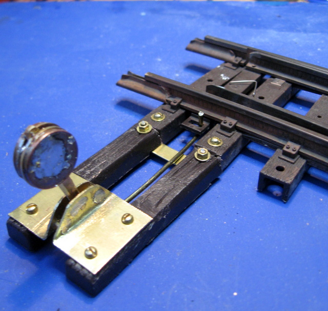
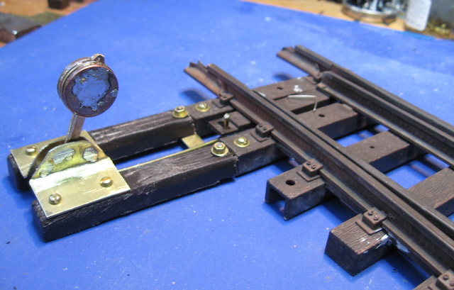
Version 2
- IMG_8903.JPG (153.94 KiB) Viewed 7594 times
.
- IMG_8901.JPG (116.28 KiB) Viewed 7594 times
.
- IMG_8899.JPG (103.55 KiB) Viewed 7594 times
.
Happier with the look of this one. I've fitted it to a Piko point which seems to have a shorter throw than the LGB equivalent. The lever now moves far less and so I think I will need to lower the pivot, to shorten the distance between it and the linkage to the tie bar, thereby increasing the amount of throw needed so the weight gives a bit more resistance and holds the blades more tightly against the stock rails. Not tried trailing stock through either yet, so not sure whether I've got the resistance right - maybe some fine tuning needed.
Rik
PS - I've run out of 1c Euro coins so will have to wait until the brass rod arrives before I can continue with development.
Re: Point lever
Posted: Mon Oct 22, 2018 6:15 pm
by tom_tom_go
I know you like making stuff yourself Rik but I have a few of Cliff Barkers point levers and they are very nice and can be modded if required:
http://www.cliffbarker.me.uk/NarrowGaugeTrack.html
Re: Point lever
Posted: Mon Oct 22, 2018 11:12 pm
by ge_rik
Thanks Tom
Not bad at £6.50 each. Might be worth a try.
Rik
Re: Point lever
Posted: Tue Oct 23, 2018 8:08 am
by FWLR
Genius at work again…..
Re: Point lever
Posted: Tue Oct 23, 2018 9:17 am
by GTB
tom_tom_go wrote: ↑Mon Oct 22, 2018 4:47 pm
Graeme, does the point you are installing need to reset the same way each time? If so, just use a spring or a piece of wire to allow it to reset each time.
That's one of the alternatives I'm considering, but I'd like to run trains in both directions on the mainline. A spring soft enough to allow all my rolling stock to trail the point blades may be too soft to adequately lock them against facing movements.
I'll probably end up making some pneumatic point motors and remote control all the turnouts on the triangle from an easily accessible location. Or buy the bits, the cost is about the same as using r/c servos, with no electrickery involved and less parts to go wrong.
Regards,
Graeme
Re: Point lever
Posted: Fri Oct 26, 2018 6:48 pm
by ge_rik
GTB wrote: ↑Mon Oct 22, 2018 4:12 pm
I'll be interested to see how you go with making the point blades trailable.
One of the turnouts on my planned triangular junction won't be easily accessible when the bridge is in place. I've been contemplating how to make it trailable so I don't have to install a remote lever, but haven't cut metal yet.
Regards,
Graeme
Hi Graeme
Not much success so far. I have altered the geometry on my prototype so the lever lies almost horizontal after throwing the blades, thereby increasing the effort needed to raise the weight when flanges pass through. However, the weight is insufficient at present to return the blades so they lie against the stock rails. Partly this is because of inherent friction in the tie bar of the Piko point. I'll try increasing the mass of the balance weight and reducing the friction on the tie bar - but I suspect there is a critical point at which the mass of the balance weight will prevent the flanges from passing through.
Interesting stuff, though. I now wish I'd paid more attention in my A Level Physics classes
Rik
Re: Point lever
Posted: Fri Oct 26, 2018 11:25 pm
by IanC
ge_rik wrote: ↑Fri Oct 26, 2018 6:48 pm
Interesting stuff, though. I now wish I'd paid more attention in my A Level Physics classes
Rik
I wish I could remember any of my Physics classes! All long since forgotten

Re: Point lever
Posted: Sat Oct 27, 2018 8:11 am
by FWLR
ge_rik wrote: ↑Fri Oct 26, 2018 6:48 pm
Interesting stuff, though. I now wish I'd paid more attention in my A Level Physics classes
Rik
I remember my Physical Classes…..
Re: Point lever
Posted: Mon Oct 29, 2018 2:23 pm
by IrishPeter
Even if you had paid attention in Physics I don't think it would be that much help. In railway applications one has all sorts of real world problems - bird poop, loose grit, slugs leaving trails, etc., etc., which can mess up even NASA's calculations, and they have a bit more than an pocket calculator and a beer mat to work it out with. I have to declare an interest in the results of your experiments as the CLR will hopefully be constructed using trailable points for the passing loops so I can simplify the signalling etc., outside.
Cheers,
Peter in Va
ge_rik wrote: ↑Fri Oct 26, 2018 6:48 pm
GTB wrote: ↑Mon Oct 22, 2018 4:12 pm
I'll be interested to see how you go with making the point blades trailable.
One of the turnouts on my planned triangular junction won't be easily accessible when the bridge is in place. I've been contemplating how to make it trailable so I don't have to install a remote lever, but haven't cut metal yet.
Regards,
Graeme
Hi Graeme
Not much success so far. I have altered the geometry on my prototype so the lever lies almost horizontal after throwing the blades, thereby increasing the effort needed to raise the weight when flanges pass through. However, the weight is insufficient at present to return the blades so they lie against the stock rails. Partly this is because of inherent friction in the tie bar of the Piko point. I'll try increasing the mass of the balance weight and reducing the friction on the tie bar - but I suspect there is a critical point at which the mass of the balance weight will prevent the flanges from passing through.
Interesting stuff, though. I now wish I'd paid more attention in my A Level Physics classes
Rik