Project Topsy

What is your latest project?
Post Reply
User avatar
philipy
Moderator
Moderator
Posts: 5079
Joined: Sun Jan 30, 2011 3:00 pm
Location: South Northants

Project Topsy

Post by philipy » Mon Jun 27, 2016 5:19 pm

So called because, like Topsy, "It just grow'd"! Rather like this post I suspect.

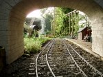
The bottom RH corner of the garden is hidden behind a large evergreen bush and for the past 20 years has been a general dumping ground for bits of broken concrete, weeds, grass clippings, tree prunings,etc, etc! When I first built my line I went round the front of said bush, but that cut the only access to the dump without removing the bridge, and has been a pain for the past few years. Soooo... last autumn I decided that a deviation was required running round the outside of the hidden corner. I just about got that sorted before the winter put things on hold. Then with 4 or 5 months bad weather I could do nothing but think and plan. The original route was still there but disconnected at one end, and with the bridge not connected at either end. Over the years I have considered the possibilty of putting a loop around the dreaded bush, but there isn't quite enough room without going down to 3ft radius or even less. Then inspiration struck, by starting from close to the junction of the deviation I could just get an acceptable gradient to take the line down under the bridge, and leave room beside the line for a path into the dead corner. It still means the bridge has to be taken out, but with the bark chippings path now laid it is actually possible to step over it, which is what I do unless I'm carrying something awkward, whereas before I was standing on flowerbed one side and broken concrete the other!
Image

Anyway, so now the line comes down under the bridge, but what to with it then? In front of the big bush we have a small paved area with a garden bench on it which faces the late afternoon sun ( what sun??). I sureptitiously slid the bench forward a couple of feet and then a day or two later with much fear and trepidation, I said, "Would you mind if I moved the bench forward to where it is now?". "I didn't know you'd moved it, it still looks the same?"... "I take that as OK, then?" It so happened that I had a couple of 3metre lengths of 8" x 3" timber lurking in the garage, so a couple of timber straps to hold them side by side and some brick piers would give me somewhere for the line to go and hold a small low level terminus station - to be called 'Lower Bench' in due course.
Image

So, back in April, when it stopped raining for a while, out came the tools and materials because I wanted to get as much done as possible before the garden came to life- "You can do what you want as long as it doesn't spoil the garden"!

The original turnout for the junction between the old line and the deviation, was operated by a manual lever next to the track at the back of a garden border. I always knew this would be a nuisance, but in practice was unlikely to be used much. However the adjacent additional turnout to give access to the new line is going to get much more use and some sort of electric operation is needed. I had 3 Tortoise point motors in stock from many years ago. These are pretty powerful beasties and although intended for indoor layouts, they have plenty of umph and sufficient throw for 32mm. However they do need a changeover switch to reverse the throw, and given the location this would be problematic. I re-read Riks' blogs on Peckforton's turnouts and signals and liked the idea of the cheap Chinese garage door type radio control, but all this Picaxe stuff is beyond me. I tried to work it out but it seems to need a degree in Geekness which I don't have, so I looked for a workaround. This was simple after a bit of thought, mount a DPDT relay on top of the point motor and use the RC to send a simple on/off to the coil, and with the relay contacts wired as a changeover switch to feed the point motor, job done.
Image

Of course, being intended for indoor use, the Tortoises are a long way from being waterproof, so they needed protecing in some way. I didn't really want two nondescript trackside boxes close together, so a lever frame shelter housing both of them seemed like a good idea, but somehow that morphed into a proper small signal box. The only snag now was that both point motors were around a foot from their respective turnouts and the only answer is real mechanical rodding. Fabricated from brass rod, NS sheet and brass nuts and bolts, it works very well, although there is still one issue to work out, visible route setting indication.
Image

So now I have a working system, all it needs is a 12v power supply at the bottom of the garden! Again, Rik supplied the answer, a 12v lead acid battery. Rik houses his on a shelf under the track, but on my line this would be buried behind foliage and pretty inaccessible. Then I realised that the dimensions of the battery would allow it to fit inside a scale 12ft x 7ft Platelayers hut, so I now had to build one of those as well. There was also sufficient space inside for the RC receiver, and since I had deliberately bought a 12 channel unit, it will be fairly simple to run wires to the turnouts on Lower Bench, one day.
Now, if you look just to the left of the door, you'll see that the ganger has left a hurricane lamp hanging on a nail. He has a habit of leaving it burning which by some miracle exactly coincides with my own habit of not switching things off! The hurricane lamp is a cut and filed LED plus bits and pieces of plastic and using a dead button cell for the oil reservoir.
Image

Image

Just as I was getting to the end of this marathon, the subject of 'conveniences' was brought up by Grant, and my effort on the subject has been posted elsewhere. The operating electronics for it, ( timer and voltage regulator) are also housed in the PW hut ( in the white box).

It still needs some tidying up of the ballast and various other minor details, but thats pretty much 'it', until I can start on the station.
Image
Philip

jim@NAL
Driver
Driver
Posts: 1115
Joined: Sun Sep 23, 2012 11:01 am
Location: haverhill suffok

Post by jim@NAL » Mon Jun 27, 2016 9:31 pm

very good very well hidden in the building

User avatar
Soar Valley Light
Driver
Driver
Posts: 1451
Joined: Sun Dec 08, 2013 5:18 pm
Location: North West Leicestershire

Post by Soar Valley Light » Mon Jun 27, 2016 10:24 pm

Excellent! Great ideas, well executed. I love it.

The little group of buildings look totally convincing and create a very realist little scene.

Andrew
"Smith! Why do you only come to work four days a week?
"'cause I can't manage on three gaffer!"

User avatar
LNR
Driver
Driver
Posts: 1542
Joined: Sat Feb 27, 2016 5:26 am
Location: Australia

Post by LNR » Tue Jun 28, 2016 12:05 am

What a great tale of inspiration Philip. It has all the elements, a land grab cleverly disguised, ongoing planning, dicing with the weather. I'm particularly taken with your point rodding and bell cranks, as I'm about to start on that myself. I use an old adage "if all else fails, do it like the real ones",it seems to fit your case well.
Grant.
PS I think there's more than one electronic wizard on this forum.

User avatar
philipy
Moderator
Moderator
Posts: 5079
Joined: Sun Jan 30, 2011 3:00 pm
Location: South Northants

Post by philipy » Tue Jun 28, 2016 6:38 am

Thanks chaps.

Grant,
I'm no electronic wizard I'm afraid, I wish I was. I know enough to be able to follow a circuit diagram and solder the bits together, but that's about it.

FWIW, I used 1.5mm brass wire/rod for the point rodding and the longest single length is about 280mm. At that, there is just the tiniest big of visible flex in the rod as it pushes, any more and it would require intermediate stools. I am a wee bit concerned about the heat expansion of brass, but since the  final drive from the motor is via a steel spring wire, I'm hoping that any expansion in the rod will simply flex the spring. If it ever stops raining I might find out!

I mentioned 'visible route setting indication', and I have it in mind to use semaphore signals, but I suspect they will have to wait until next winter. Too many other things need attention atm.
Philip

User avatar
LNR
Driver
Driver
Posts: 1542
Joined: Sat Feb 27, 2016 5:26 am
Location: Australia

Post by LNR » Tue Jun 28, 2016 9:00 am

With electronics I claim to know enough to get me into trouble, but not enough to get me out of it.
Regarding point rodding I was reading the "haggerleases" (hope that's right) railway page last night, and he has expansion cranks in his rodding. I wasn't going to worry, might have to review that. Whilst the dwarf signal for road 4 should be cable operated, I want to cross the yard with rodding as the weight on it is small. I have been saving a very British made umbrella because it consists of galvanised metal "U" shape arms. You can probably guess where I'm going with this. I'm sure you guys would have access to these, very handy even have hinged sections in them.
Grant.

User avatar
tom_tom_go
Driver
Driver
Posts: 4824
Joined: Wed Feb 23, 2011 3:08 am
Location: Kent, UK
Contact:

Post by tom_tom_go » Tue Jun 28, 2016 12:44 pm

Great work Phil.

Do you points move slowly with the Tortoise motors as I used these in OO years ago on my layout:

CLICK>>Slow action points video

User avatar
philipy
Moderator
Moderator
Posts: 5079
Joined: Sun Jan 30, 2011 3:00 pm
Location: South Northants

Post by philipy » Tue Jun 28, 2016 2:18 pm

Hi Tom,
Here is a quick video, which I've just taken. I haven't had a chance to free things up properly since ballasting and I think some SRB has got on the joints, so it is a bit jerkier than when I was testing. We are off on hols later today so no time to sort it now!

<object width="640" height="480"><param name="movie" value="http://www.youtube.com/v//SBiwzSV0D2A?v ... ram><param name="allowFullScreen" value="true"></param><param name="allowscriptaccess" value="always"></param><embed src="http://www.youtube.com/v//SBiwzSV0D2A?v ... n_US&rel=0" type="application/x-shockwave-flash" width="640" height="480" allowscriptaccess="always" allowfullscreen="true"></embed></object>

https://youtu.be/SBiwzSV0D2A
Philip

User avatar
Soar Valley Light
Driver
Driver
Posts: 1451
Joined: Sun Dec 08, 2013 5:18 pm
Location: North West Leicestershire

Post by Soar Valley Light » Tue Jun 28, 2016 6:27 pm

Hi Philip,

Your little video clip looks very realistic. I shouldn't worry about a bit of 'lumpiness' in the operation, points are often like that in real life. It sometimes takes two or three 'bites' to get them over or put them back. I guess it's a bit like the bounce of a signal arm in reverse!

Before we know where we are we shall have people carying out compensation calculations for their garden railways to work out where to put the compensators! :lol:

Keep up the good work,

Andrew
"Smith! Why do you only come to work four days a week?
"'cause I can't manage on three gaffer!"

User avatar
ge_rik
Administrator
Administrator
Posts: 6558
Joined: Sun Oct 25, 2009 10:20 pm
Location: Cheshire
Contact:

Post by ge_rik » Tue Jun 28, 2016 7:49 pm

Great work, Philip.
I'm glad my musings were of some help - but I think your solution is much more elegant than mine - I do like the tortoise motor action - a lot more realistic than solenoids.

Rik
PS - Your garden looks great as well BTW
------------------------
Peckforton Light Railway - Blog Facebook Youtube

Post Reply

Who is online

Users browsing this forum: No registered users and 15 guests