Construction of the MQR

A place for the discussion of garden railways and any garden style/scale portable and/or indoor layouts
RichMQR
Cleaner
Cleaner
Posts: 54
Joined: Wed Jan 07, 2015 3:57 pm
Location: Herefordshire, UK

Construction of the MQR

Post by RichMQR » Fri Jan 09, 2015 7:07 pm

So, after reading many inspiring words on this forum I have finally taken that long delayed first step and have started construction of my railway.

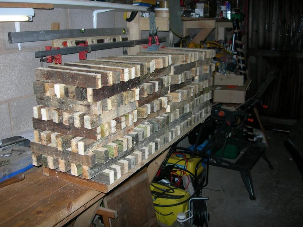
This is what 10 tons of ballast looks like:
Image

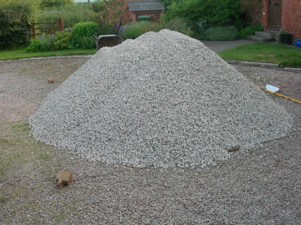
I realise that most of you here use 32 or 45mm, so don't be alarmed, this is not 100 miles of 32mm, it is going to be about 150m of 5inch ground level line. Although this is not the main subject discussed here, I hope it will be of some interest.

In reality, construction has gone beyond this point, but I've been taking photos along the way and plan to tell the story as a "how I did it" because I have always found that approach the most interesting when others have done it and having learnt so much, I want to offer something in return. Please be aware that many of these things will be my mistakes!

I am lucky in that I have plenty of space for 5inch, about 3 acres. However, much of this is an orchard that is commercially harvested and even 5inch track does not mix well with 4wd tractors. This means that the usable area is much less and the planned route stays quite near to the house.

Though I have space, I do not have unlimited funds, and I suspect that what I am building will actually cost less that some of the more extensive 32mm efforts described here. Much will be hand built (except the locomotives, I'm not that skilled an engineer)

Further instalments will follow providing there is some sign of interest!
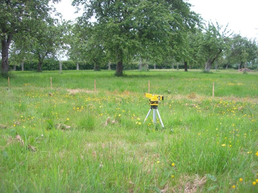
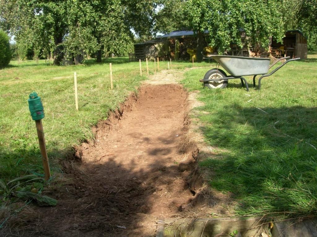
The view ahead:
Image

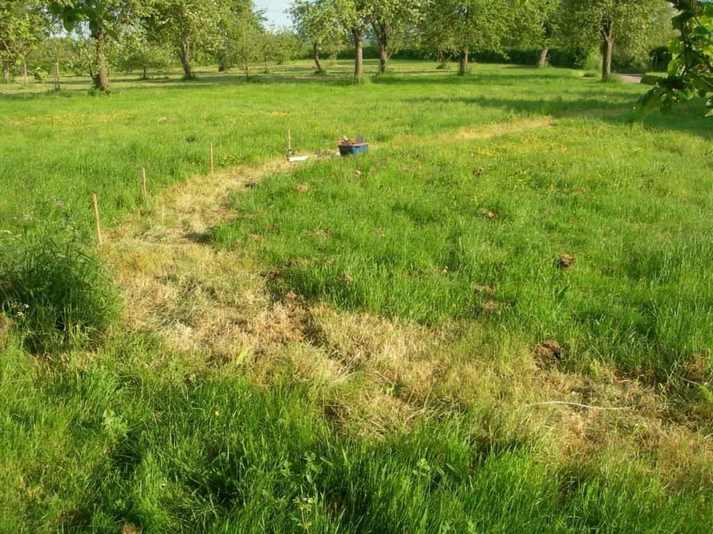
Rough line of the trackbed sprayed out to clear the tough field grass.

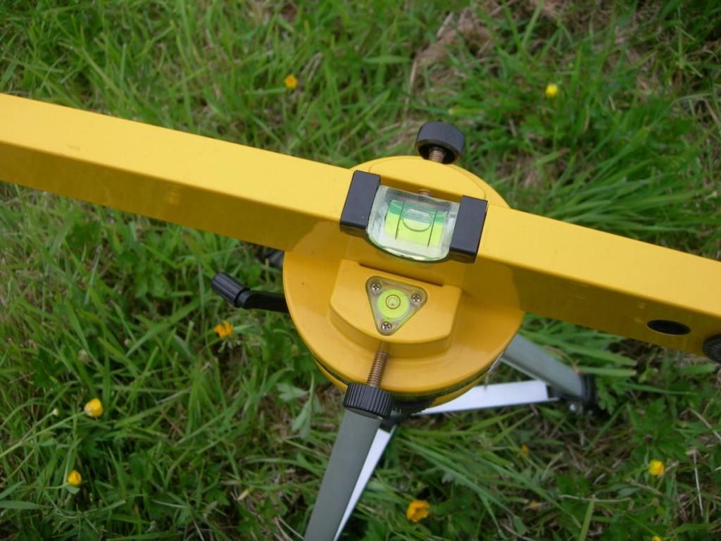
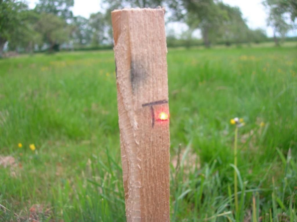
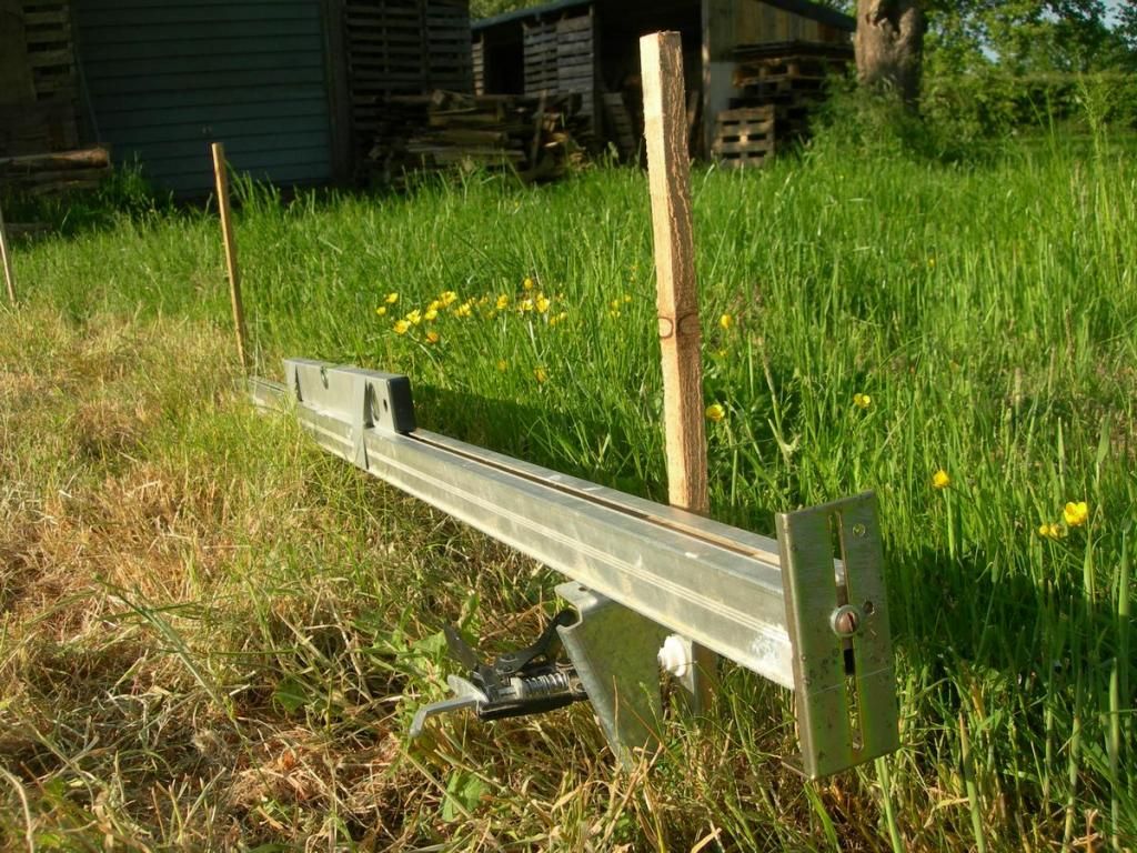
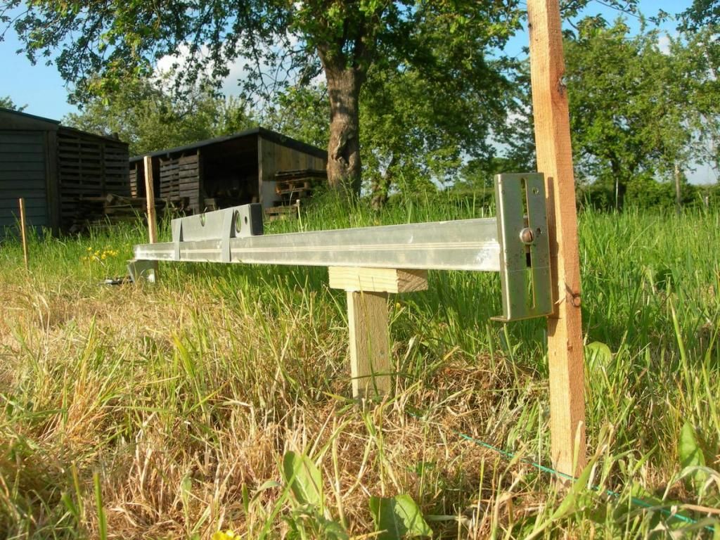
Coming up:  Surveying and the mind bending process of finding levels.

User avatar
steamie1
Trainee Driver
Trainee Driver
Posts: 685
Joined: Tue Nov 13, 2012 11:04 pm

Post by steamie1 » Fri Jan 09, 2015 7:13 pm

Yes Yes! we all like a work in progress shot. Thanks!

Joe
Fireman
Fireman
Posts: 465
Joined: Sat Dec 20, 2014 6:18 pm
Location: West Midlands

Post by Joe » Fri Jan 09, 2015 7:14 pm

Wow, looks like a lot of space even though you cant use all of it, could you build a 32mm line as well to make up for all that space? The thing is youve got a pretty much blank canvas so you can make it and landscape it how you like, i look forward to updates!
Steam is highly under rated

User avatar
Dannypenguin
Trainee Driver
Trainee Driver
Posts: 632
Joined: Tue Feb 26, 2013 9:57 am
Location: Forest of Dean, UK
Contact:

Post by Dannypenguin » Fri Jan 09, 2015 8:06 pm

Looking forward to this :thumbright:
Dan

Visit the PFLR website - http://poultonfarmlightrailway.webs.com/
Dean Forest Railway Society website - http://dfrsociety.org/

jim@NAL
Driver
Driver
Posts: 1115
Joined: Sun Sep 23, 2012 11:01 am
Location: haverhill suffok

Post by jim@NAL » Fri Jan 09, 2015 9:10 pm

good luck this is going to be rather good I think

kandnwlr
Trainee Driver
Trainee Driver
Posts: 998
Joined: Fri Dec 02, 2011 3:14 pm
Location: Alsace, France

Post by kandnwlr » Fri Jan 09, 2015 9:12 pm

Keep the pics coming. :shock:

RichMQR
Cleaner
Cleaner
Posts: 54
Joined: Wed Jan 07, 2015 3:57 pm
Location: Herefordshire, UK

Post by RichMQR » Fri Jan 09, 2015 9:50 pm

The last picture above shows some marker posts along the route. These are part of the levelling process. This first stage of the railway is simply a continuous run which circles the drive and garage and has the curve you can see out through the edge of the orchard. Now, the orchard looks pretty flat, but, as many here have said before, appearances are deceptive, and some quite significant earthworks lie ahead. There will be a maximum gradient of 1:50 and a minimum radius curve of 22ft. Preferably not both at the same place!
Armed with a cheap laser level, I measured the fall from the highest point to the lowest and established a datum peg within the circuit from which all other levels were measured. The level was set there and “scanned” over all the marker posts to set a basic level.

Image

Image

Image

Lots of messing around came next to try to equalise the amount of cuttings at the higher ground and embankments over the lower levels. There are also a few fixed levels where the line will cross the drive and various paths.

The next device is a “spirit slope”. Basically a spirit level taped to a straight edge with an adjustable foot at one end that can be set to the required amount of fall over the length of the level. Resting on two pegs, this can easily give you the correct gradient.

Image


Image

User avatar
Dr. Bond of the DVLR
Retired Director
Retired Director
Posts: 4485
Joined: Tue Jun 09, 2009 9:43 pm
Location: Suffolk
Contact:

Post by Dr. Bond of the DVLR » Fri Jan 09, 2015 10:07 pm

Marvelous stuff. I am thoroughly looking forward to learning more!
Image
The railway which people forgot
(to build)

User avatar
sstjc
Fireman
Fireman
Posts: 442
Joined: Mon Dec 22, 2008 10:47 am
Location: Faversham Kent
Contact:

Post by sstjc » Sat Jan 10, 2015 12:37 am

Keep it coming. I look forward to following this build.
Regards
Barry

www.5inchrail.com

RichMQR
Cleaner
Cleaner
Posts: 54
Joined: Wed Jan 07, 2015 3:57 pm
Location: Herefordshire, UK

Post by RichMQR » Sat Jan 10, 2015 7:49 am

Thank you all for the encouraging comments. The story will continue to evolve as I get the time to write it. Although at the moment this is a historical record, I'd still be interested to hear comments and suggestions - I can always do things better on the next phase.

User avatar
Soar Valley Light
Driver
Driver
Posts: 1451
Joined: Sun Dec 08, 2013 5:18 pm
Location: North West Leicestershire

Post by Soar Valley Light » Sat Jan 10, 2015 6:07 pm

Hi Rich,

Your level control is excellent. Nice and simple basic stuff, exactly what's needed for reliable and accurate construction on any railway.

Super job, I can't wait for the next instalment.

Andrew
"Smith! Why do you only come to work four days a week?
"'cause I can't manage on three gaffer!"

jim@NAL
Driver
Driver
Posts: 1115
Joined: Sun Sep 23, 2012 11:01 am
Location: haverhill suffok

Post by jim@NAL » Sat Jan 10, 2015 7:45 pm

looking very good are you digging this out my hand ???.one suggestion is you could get a water level

http://www.ebay.co.uk/itm/like/11142100 ... 0&ff14=108
there very good over long distances and easy to use .good luck looking forward to seeing more pics and progress

RichMQR
Cleaner
Cleaner
Posts: 54
Joined: Wed Jan 07, 2015 3:57 pm
Location: Herefordshire, UK

Post by RichMQR » Sat Jan 10, 2015 9:46 pm

Good suggestion on the water level, I'll give this a try on phase 2 which will have to cross more uneven ground.

Before we continue with construction, a little background. I haven't got a detailed back-story for this line. I'm always impressed with the imagination shown by some people here. The flavour however is definitely TLC (or Top Left Corner (of Wales), as one of our favourite railways, the FR/WHR now call it) I'm a long term supporter of these railways and spend my non-railway (and non working) time walking, often in the TLC. This has included walking much of the trackbed of the WHR before reconstruction, including over the open girders of Glanrafon bridge. The point of this digression is to explain that one of the things that interests me about railways, particularly the NG is the track itself. Passing trains are great, but I can also be happy walking from T-y-B to Tanygrisiau via Dduallt when no trains are running, just to see the track as there are footpaths near for most of the route. So, I want to create a railway that looks good when not in use, which is after all, most of the time!

To get such a result involved digging.
Image

sometimes quite deep and through hardcore. We actually uncovered a surprising amount or rubble in what we thought was an old orchard. This is where a path is crossed. There will be a removable bridge here. You can see the cutting ahead turning right. Where it leaves the picture is about the transition from cutting to embankment

Image

RichMQR
Cleaner
Cleaner
Posts: 54
Joined: Wed Jan 07, 2015 3:57 pm
Location: Herefordshire, UK

Post by RichMQR » Sat Jan 10, 2015 10:04 pm

Of course, digging isn't much fun in the rain or the dark, and since we are going to need track too, here are some sleepers

Image

I know you can buy these, even in plastic, but my method is more basic and cheaper, though it does take a while, as I needed many hundreds. They are cut on a saw table to a standard size then soaked in preservative in old 10Ltr paint tubs, which turn out to be just the right depth for the sleepers on end. I have a basic jig, on which these sleepers are resting, for straight track. I use a gauge to keep spacing regular, but not with precision, this is NG after all.

Image

User avatar
Soar Valley Light
Driver
Driver
Posts: 1451
Joined: Sun Dec 08, 2013 5:18 pm
Location: North West Leicestershire

Post by Soar Valley Light » Sat Jan 10, 2015 10:31 pm

Hi Rich,

I know just what you mean about railways without the trains - I feel exactly the same. Track is the primary infrastructure when there are no trains about and so it's appearance in model form is important when it comes to creating a convincing sense of realism.

Almost all companies railway track of whatever gauge was built to some sort of standard. Even if they contracted out the construction and maintenance there must have been some guide, otherwise how would the contractor know what rail length to use or how many sleepers to use per length, never mind the fastenings to use. Of course, it may have been the contractors themselves who made, or at least informed this decision (basically design and build), most contractors had a standard of their own for work not specified by the client.

Most (probably all) standards would be informed by 'industry best practice'. The bottom line though, for our own railways, is that we can make up our own standards, which can be as detailed or vague as we choose. One thing I've almost always found though, is that sleeper spacing almost always closes up on at least three sleepers either side of a fishplated joint. It makes sense as it provides increased support to the joints and helps prevent 'dipping' of joints.

All the best,

Andrew
"Smith! Why do you only come to work four days a week?
"'cause I can't manage on three gaffer!"

Big Jim
Moderator
Moderator
Posts: 2694
Joined: Sat Jul 06, 2013 5:28 pm
Location: Near Llanelli

Post by Big Jim » Sat Jan 10, 2015 10:41 pm

Impressive start.
Lets have more pics please.
Don't be to sure you can't build your own loco. I have seen some very good battery 5' or 71/4' locos built by people with little or no engineering skills. Dexion can be used to build a chassis. While you may have to buy axles and wheels most of the work can be done 'in house'
If at first you don't succeed, use a bigger hammer!

RichMQR
Cleaner
Cleaner
Posts: 54
Joined: Wed Jan 07, 2015 3:57 pm
Location: Herefordshire, UK

Post by RichMQR » Sun Jan 11, 2015 7:06 pm

I will certainly be building rolling stock, maybe I'll try a locomotive if that works out OK.

As well as sleepers you need rail. After much consideration of the merits of steel and aluminium I eventually decided to go with aluminium. This is 16mm section from Cromar White. The bit of metal lying across the rails is the sleeper drilling guide. It is actually part of a bracket for a central heating radiator. The useful thing is that it is of L section so that it easily sits over a sleeper, as in the photo, and allows me to drill holes for the zinc plated roofing nails that are going to hold the rail down. The holes drilled are a tight interference fit on the nails, so that a couple of hammer blows will seat them down tight, and the drilled holes help maintain gauge.

Image

I also use a track gauge, made out of an old window handle with notches filed to a snug fit on the rail head and a wooden spacer to keep the sleeper spacing about right. (are you getting the idea that most things are recycled junk ... quite true)

Image

you can see one of the nails here pushed by hand into a drilled hole before the sleeper is pushed back against the upstanding back of the jig and the other nails added and hammered down.

Image

The remaining sleepers for this length waiting to be fitted. This works well for straight track. Curves are more interesting!

jim@NAL
Driver
Driver
Posts: 1115
Joined: Sun Sep 23, 2012 11:01 am
Location: haverhill suffok

Post by jim@NAL » Sun Jan 11, 2015 9:39 pm

love your jig and rail spacer very good .how many sleepers are you going to need

User avatar
MDLR
Driver
Driver
Posts: 4027
Joined: Thu Jan 15, 2009 10:38 pm
Location: Near Ripley, Derbyshire, UK
Contact:

Post by MDLR » Sun Jan 11, 2015 10:27 pm

jim@NAL:107366 wrote:love your jig and rail spacer very good .how many sleepers are you going to need
I would guess at "lots" - we seemed to be drilling and creosoting sleepers for the Golden Valley Light Railway (2' gauge) for YEARS! In the end, we were barely keeping up with the track laying gang!
Brian L Dominic
Managing Director
Flagg Fluorspar Co
www.mdlr.co.uk/ff.html

RichMQR
Cleaner
Cleaner
Posts: 54
Joined: Wed Jan 07, 2015 3:57 pm
Location: Herefordshire, UK

Post by RichMQR » Sun Jan 11, 2015 10:57 pm

For this phase about 900. I did them in batches and built track panels in between.
Would have probably gone crazy doing them all in one go.

Post Reply

Who is online

Users browsing this forum: No registered users and 5 guests