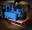
Dear all,
I am building à thornas loco powered with batteries. I modified the design to use Rick's motor support.
viewtopic.php?t=15019
Unfortunately, my link rods system between the 2 axels don't work as expected, the slave axle doesn't turn as you can see here:
Could someone help me to solve that
Thanks
Link rods issue
-
Sam95
- Cleaner

- Posts: 89
- Joined: Sat Jan 20, 2024 10:55 pm
Link rods issue
You can visit my blog
http://sam95.fr/
http://sam95.fr/
-
GAP

- Trainee Driver

- Posts: 858
- Joined: Sun Dec 23, 2012 10:34 pm
- Location: Bundaberg QLD Australia
- Contact:
Re: Link rods issue
I don't think the rods should be on the diagonal I think that they should be straight between the wheels.
Graeme
From the home of the Uppen Down Railway
https://ringbalin-light-railway.blogspo ... -page.html
From the home of the Uppen Down Railway
https://ringbalin-light-railway.blogspo ... -page.html
-
philipy

- Moderator

- Posts: 5933
- Joined: Sun Jan 30, 2011 3:00 pm
- Location: South Northants
Re: Link rods issue
I think Graeme is exactly right. Its difficult to be sure at that speed, but I think the quartering is out. If you drop the rod off one wheel, turn that wheel so that the rod goes back on the crank pin with it being horizontal, you should find the other side is now correct. If you then power it up and it goes back to oscillating, then that tells you that either the crank pin holes are probably too big or that the wheels are not firmly fixed to the axles at the correct quartering positions.
Philip
-
LNR

- Driver

- Posts: 1840
- Joined: Sat Feb 27, 2016 5:26 am
- Location: Melbourne, Australia
Re: Link rods issue
If you freeze the video at 1second, you will notice that the left hand crank is almost at top dead centre while the right hand one is about 1 o'clock indicating that your connecting rod centre to centre is too long. Rod centre to centre should be IDENTICAL to axle centre to centre.
Grant.
- Screenshot (188).jpg (43.03 KiB) Viewed 2061 times
-
Sam95
- Cleaner
- Posts: 89
- Joined: Sat Jan 20, 2024 10:55 pm
Re: Link rods issue
My rods are straight but go diagonal immediately after the first turn.
I will control there length better. I put a rivet between the crank and the rod. Should this rivet be loose or tight?
I will control there length better. I put a rivet between the crank and the rod. Should this rivet be loose or tight?
You can visit my blog
http://sam95.fr/
http://sam95.fr/
-
LNR
- Driver
- Posts: 1840
- Joined: Sat Feb 27, 2016 5:26 am
- Location: Melbourne, Australia
Re: Link rods issue
Sam, trying to help here but it is hard to explain.
Are you able to undo the rod from the "slave" axle crank pin? (presuming the one on the right!)
Now if you set the left hand crank to 3 o'clock and the right hand one the same, then offer the coupling rod up to where the right hand crank pin is, you will see that it is too long.
Before you can even setup the quartering the rods on both sides must be capable of turning the full circle of the cranks.
Grant.
-
drewzero1
- Administrator
- Posts: 837
- Joined: Fri Apr 21, 2023 4:35 pm
- Location: WI, US
- Contact:
Re: Link rods issue
Ooh, if that's the model I think it is you can certainly blame my inexperience before anything else.  I've been tweaking the original for three years now and keep finding flaws in my design, or places I might have done something differently. I'd gladly welcome any and all suggestions for if and when I think I might be ready to try making a version 2. I like the motor block you've done and might try that next, since I've already found two other ways not to do it.
It looks like the rods might be a little bit longer than the axle-to-axle measurement. Take off the rod and match it up against the axles, if it doesn't match up then you might need to make a shorter connecting rod. (Or let me know the axle-to-axle measurement you've got and I can see if I still have the OpenSCAD files for the rods, or recreate them.) I've got 50mm for both on my model but I may we'll have mixed up something in the files. I've lost a hard drive or two since then so I'll have to look and see if I have the original files.
If they are the same length, what size stock are you using for the axles and crank pins? With the short throw of the cranks and a bit of play in the axle journals and rod end, it's possible there's enough play to let the rods cross over.
Overall I'm flattered that you're building my design and hope I can help get it going! It's already looking great!
It looks like the rods might be a little bit longer than the axle-to-axle measurement. Take off the rod and match it up against the axles, if it doesn't match up then you might need to make a shorter connecting rod. (Or let me know the axle-to-axle measurement you've got and I can see if I still have the OpenSCAD files for the rods, or recreate them.) I've got 50mm for both on my model but I may we'll have mixed up something in the files. I've lost a hard drive or two since then so I'll have to look and see if I have the original files.
- Screenshot_20260322-195551.jpg (97.41 KiB) Viewed 2012 times
If they are the same length, what size stock are you using for the axles and crank pins? With the short throw of the cranks and a bit of play in the axle journals and rod end, it's possible there's enough play to let the rods cross over.
Overall I'm flattered that you're building my design and hope I can help get it going! It's already looking great!
-
LNR
- Driver
- Posts: 1840
- Joined: Sat Feb 27, 2016 5:26 am
- Location: Melbourne, Australia
Re: Link rods issue
I do hope my comments are taken as constructive and not destructive.
Further checking and freeze framing of your video Sam, when you turn the engine upside down while running I think I'm seeing that you have the cranks set at 180 degs out of phase, and not 90 degs as they should be. I could be wrong it's hard to pick up but I think that's what I'm seeing.
Grant.
Ps and as Drew says a bit of slack in the holes might be needed, though I would tend to open up rods rather than axles as they are easier to replace.
-
philipy
- Moderator
- Posts: 5933
- Joined: Sun Jan 30, 2011 3:00 pm
- Location: South Northants
Re: Link rods issue
I agree with Grant, they do look to be at 180deg - these red lines are as close as I can get to showing the angles on both sides.LNR wrote: ↑Mon Mar 23, 2026 2:19 am
Further checking and freeze framing of your video Sam, when you turn the engine upside down while running I think I'm seeing that you have the cranks set at 180 degs out of phase, and not 90 degs as they should be. I could be wrong it's hard to pick up but I think that's what I'm seeing.
- Screenshot 2026-03-23 05.35.45.jpg (239.95 KiB) Viewed 1996 times
Philip
-
Sam95
- Cleaner
- Posts: 89
- Joined: Sat Jan 20, 2024 10:55 pm
Re: Link rods issue
Thanks for your reply,
Drewzero1 : indeed I used your files and also philipy files of its modified design of your small loco. At the begining I thought that the problem was from the 3d printed rods not stiff enough. So I tried to make them with copper.
My axle lenght is 52mm.
LNR : indeed my cranks are set at 180deg..... So I must set them to 90° I was not aware of that..
You can visit my blog
http://sam95.fr/
http://sam95.fr/
-
LNR
- Driver
- Posts: 1840
- Joined: Sat Feb 27, 2016 5:26 am
- Location: Melbourne, Australia
-
Durley

- Trainee Fireman

- Posts: 181
- Joined: Sun Apr 14, 2024 8:36 pm
Re: Link rods issue
This diagram might be helpful to explain quartering, this is an 6 coupled wheel arrangement but the same principles apply to four coupled:
Image borrowed from here: http://www.steves-workshop.co.uk
- IMG_5811.jpeg (30.42 KiB) Viewed 1966 times
-
drewzero1
- Administrator
- Posts: 837
- Joined: Fri Apr 21, 2023 4:35 pm
- Location: WI, US
- Contact:
Re: Link rods issue
I meant to say it might have too much slop/slack already, especially if it's a 3mm brass rod. We don't have metric sizes available in the local hardware store so I designed it for 1/8 inch rod (3.175mm) though it might be almost close enough. Sorry, I never thought about sharing while I was originally making it.LNR wrote: ↑Mon Mar 23, 2026 2:19 am I do hope my comments are taken as constructive and not destructive.
Further checking and freeze framing of your video Sam, when you turn the engine upside down while running I think I'm seeing that you have the cranks set at 180 degs out of phase, and not 90 degs as they should be. I could be wrong it's hard to pick up but I think that's what I'm seeing.
Grant.
Ps and as Drew says a bit of slack in the holes might be needed, though I would tend to open up rods rather than axles as they are easier to replace.
-
Sam95
- Cleaner
- Posts: 89
- Joined: Sat Jan 20, 2024 10:55 pm
Re: Link rods issue
I tried to modify quartering with 90° and it works !
More adjustment are requested to improve my system; but at least all the wheels turn in the same direction !!
More adjustment are requested to improve my system; but at least all the wheels turn in the same direction !!
You can visit my blog
http://sam95.fr/
http://sam95.fr/
-
philipy
- Moderator
- Posts: 5933
- Joined: Sun Jan 30, 2011 3:00 pm
- Location: South Northants
-
drewzero1
- Administrator
- Posts: 837
- Joined: Fri Apr 21, 2023 4:35 pm
- Location: WI, US
- Contact:
-
LNR
- Driver
- Posts: 1840
- Joined: Sat Feb 27, 2016 5:26 am
- Location: Melbourne, Australia
Re: Link rods issue
Good one Sam, glad you got it sorted.
Grant.
Grant.
Who is online
Users browsing this forum: No registered users and 2 guests