
Hello all,
In this post I will try to describe my radio control system based on Arduino and nRF2401L module.
First of all I would like to apologise for my English, and also tell you that I am not an expert in electronic or programming. My skills are limited and I am only able to follow internet tutorials and adapt them to my desires.
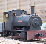
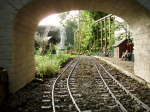
As you can see I am pretty new in garden railroading, and my layout is small. But I immediately noticed problems with the track power system, thus I searched how to change to battery powered loco and remotely controlled.
Unfortunately, my budget is not extensive, so the plug and play system are a little bit to expensive for me, and I really like DIY projects. So I started my researches on internet. First I thought to use Arduino and Bluetooth module to control the train via my smartphone but I saw few cons:
- The screen not very readable in the sun
- Tactile control no physical buttons
- I would like to play with my last son latter and a crash proof transmitter will be necessary!!
So I looked to radio transmission like for other RC models like Boat, planes and cars, but the transmitters are not so friendly to control a train from my point of view.
I finally discovered the nRF24L01 module and decided to try this solution. Actually, I only have 1 loco but I hope to have 2 or 3 more in the future, so I have 2 possibilities:
- 1 simple transmitter per loco
- 1 more complex transmitter for all loco (like my Roco multimaus on my N scale Layout)
I chose the second option.
Last point the name I gave to my project: T.T.2.J is for Telecommande Train de Jardin, you can translate as Radio Control for Garden Train
DIY Arduino radio control for garden train
DIY Arduino radio control for garden train
Last edited by Sam95 on Fri Mar 01, 2024 9:02 am, edited 1 time in total.
Re: DYI Arduino radio control for garden train
After this long intro let starts with the transmitter side:
Here are my specifications:
- User friendly interface with a screen and a rotary encoder to use a menu
- Potentiometer to control the loco FWD and REV
- A switch for emergency stop
- Battery powered transmitter
- 3D print case
- Use of Arduino UNO or MEGA in stock at home
- Cheap nRF24L01 module
Here is how I connect all the peripherals to the Arduino MEGA 2560:

FOR THE nRF24L01

VCC to 3V3
GND to GND
CSN to pin 49
CE to pin 48
MOSI to pin 51
SCK to pin 52
MISO to pin 50

I add a 10uF capacitor between GND and VCC on the module to improve powersupply
The potentiometer to control the loco is connected:

1 pin to GND
1 pin to 5V
Center pin to A2
LCD 20x4 with I2C interface is connected:
https://lastminuteengineers.com/i2c-lcd ... -tutorial/

GND to GND
VCC to 5V
SDA to SDA (20)
SCL to SCL (21)
The rotary encoder is connected:

GND to GND
+ to 5V
SW to pin 8
DT to pin 2
CLK to pin 3
The emergency stop switch
is connected via a pull down resistor to pin 9

Here are my specifications:
- User friendly interface with a screen and a rotary encoder to use a menu
- Potentiometer to control the loco FWD and REV
- A switch for emergency stop
- Battery powered transmitter
- 3D print case
- Use of Arduino UNO or MEGA in stock at home
- Cheap nRF24L01 module
Here is how I connect all the peripherals to the Arduino MEGA 2560:
FOR THE nRF24L01
VCC to 3V3
GND to GND
CSN to pin 49
CE to pin 48
MOSI to pin 51
SCK to pin 52
MISO to pin 50
I add a 10uF capacitor between GND and VCC on the module to improve powersupply
The potentiometer to control the loco is connected:
1 pin to GND
1 pin to 5V
Center pin to A2
LCD 20x4 with I2C interface is connected:
https://lastminuteengineers.com/i2c-lcd ... -tutorial/
GND to GND
VCC to 5V
SDA to SDA (20)
SCL to SCL (21)
The rotary encoder is connected:
GND to GND
+ to 5V
SW to pin 8
DT to pin 2
CLK to pin 3
The emergency stop switch
is connected via a pull down resistor to pin 9
Last edited by Sam95 on Fri Mar 01, 2024 9:09 am, edited 2 times in total.
Re: DYI Arduino radio control for garden train
Now let’s talk about the code:
I chose to use nRFLite library to control the module, this library is easy to use with an Ardunio because many parameters are already configured and it requests only few lines of code.
I use the LiquidCrystal_I2C library for the screen and Rotary and OneButton libraries for the encoder. All that come from several tutorials on internet.
The nRF24L01 module needs to have a kind of address for the transmitter and the receiver. The transmitter sends data to a specific receiver and the receiver is listening a specific transmitter. If I want to control multiple locos, I need 1 address for the transmitter and several addresses 1 for each receiver . I need to have the possibility to change the receiver address into the transmitter to select the loco I can control. With the nRFLite library this address is only a simple digit and can be associated to a variable. So I can change the value of the variable via the LCD menu each time I want to change the controlled loco.
This variable is the LOCO_ADD_Value
Concerning the Potentiometer reading it is straight forward, I read the analog data from the pin and send it to the receiver.
Same process for the emergency stop but by checking the changing state of the push button as it is a momentary switch.
The most complicated part of the code is the MENU, I only follow an already written code and adapt it to my spec. The tutorial was in French and the code is well commented in French. I tried to translate all the comments for you
One of the hardest point for me was to understand how to send more than 1 variable by radio. Indeed I understood that it is possible to send only 1 variable, but this one can be associated to a structure. And that structure can contain several variables data. So we have to write the datas in the structure and then send the variable associated by radio. In the receiver we decode the data by filling also the same structure.
I also add a voltage reading and display for the battery to protect them indeed the 2 18650 batteries must not drop bellow 2.5v each element so I display the voltage on the on the LCD screen. The measurment is done thrue a voltage divider because the analog pins of arduino are only able to read 0 to 5v.
Here is the full code for the transmitter :
Code: Select all
// T.T.2.J project

#include <LiquidCrystal_I2C.h>  // Library for I2C LCD screen
#include <Rotary.h>             // Library for encoder (Horaire/Antihoraire)
#include <OneButton.h>          // Library for encoder push switch

#include "SPI.h"
#include "NRFLite.h"  // Library for radio trnasmission

// ************   HARDWARE declaration   *************
LiquidCrystal_I2C lcd(0x27, 20, 4);  // addresse I2C 0x3F for NXP chip; or 0x27 for Texas instrument, screen size 20 rows, 4 lines

//**** rotary encoder pins S1, S2 and key:
Rotary myRotary = Rotary(2, 3);  // object myRotary (S1, S2 on Pins 2,3)
OneButton key(8, true);          // object push key on Pin 8; active_low = true (pullup)

// **********  constant and variable declaration  *************
String menuItems[2] = { "LIGHT: ", "LOCO_ADD: " };  //2 values string for the menu
String menuLIGHT[2] = { "  OFF   ", "  ON     " };  //2 values string for the menu

int menuCounter = 0;  // rotary encoder counter(0 and 1 for 2 éléments)


bool selectedLIGHT_flag = false;                        // flag to change value from ("ON",  "OFF")
bool memselectedLIGHT_flag = selectedLIGHT_flag;        //memory for LIGHT flag
bool selectedLOCO_ADD_flag = false;                     // flag to allow change of PWM value associated to loco address
bool memselectedLOCO_ADD_flag = selectedLOCO_ADD_flag;  // memory LOCO ADD flag

bool LCD_flag = true;         // to allow screen modification
bool Selection_flag = false;  // update selection

int LIGHT_Value = 0;  //default value item 1 (LIGHT)
int LOCO_ADD_Value = 10;  //default value item 2 (LOCO ADD)


boolean etatLIGHT;                       // HIGH / LOW
volatile boolean flag_clignote = false;  //

//***************** VOLTAGE MEASURMENT **********************************
// The max value on Arduino ANALOG entry is 5v
// to measure 10V it is necessary to use a voltage divider  = (R1/(R1+R2)) exemple of ratio 1/2 (R1 = R2 = 10Kohm)
// for 15V need a ration of 1/3 (R1 = 10Kohm, R2 = 20Kohm)
// for 16V need a ration of 1/3.2 (R1 = 10Kohm, R2 = 22Kohm)
// in our case with 2 18650 battery the max voltage is 8.4v, here is the resistors needed
const float R1 = 10000;          // R1
const float R2 = 6800;          // R2 = 6800 for 8.4v

float digitalVolt = 0;          // for digital reading on  A0 ==> 0...1023
float analogVolt = 0;           // to convert in analog: 0...5v
float vBatt = 0;                // measured voltage
float previous_analogVolt = 0;  // previous value

      // ***************** Functions for voltage measurment **************
float vInput(float a, float b, float c);
// void checkBatt();


// ************** CONSTANT and VARIABLE for radio transmission **********************
int DESTINATION_RADIO_ID = LOCO_ADD_Value;  // Ident of receiver corresponding to the loco address
const static uint8_t RADIO_ID = 1;          // Ident of transmitter
const static uint8_t PIN_RADIO_CE = 48;     // PIN CE 48
const static uint8_t PIN_RADIO_CSN = 49;    // PIN CSN 49
int LAMPE = LIGHT_Value;                    // variable to send lighting data

NRFLite _radio;

int POT_Value = 0;  // Variable for the potentiometer value with default value at 0
int bpAru = 0;      // Variable for emergency stop
int bpAruMem = 0;   // variable for emergency stop memory
int ARU = 0;        // variable for emergency stop data to be trnasmitted

// ************** STRUCTURE CONTAINING THE DATA to transmit by radio **************

struct RadioPacket {
  int POT_Value;
  int ARU;
  int LAMPE;
};

RadioPacket _radioData;  // Variable associated wiht the previous strucutre

// ************** DEFINITION OF LOCO NAMES TO BE DISPLAYED ********************************************

String L10("Rusty");  // name of loco associated with address RADIO ID 10
String L11("L11");    // name of loco associated with address RADIO ID 11
String L12("L12");
String L13("L13");
String L14("L14");
String L15("L15");
String L16("L16");
String L17("L17");
String L18("L18");
String L19("L19");
String L20("L20");
String L21("L21");
String L22("L22");
String L23("L23");
String L24("L24");
String L25("L25");
String clear("             ");  // 10 spaces to clear loco name


// **************   LOGO and ICONES in custom character *********************

byte Loco1[8] = {
  0b00000,
  0b00000,
  0b11111,
  0b11100,
  0b00100,
  0b00100,
  0b00011,
  0b00011
};

byte Loco2[8] = {
  0b00000,
  0b00000,
  0b10011,
  0b10001,
  0b10001,
  0b10001,
  0b11111,
  0b11111
};

byte Loco3[8] = {
  0b00000,
  0b00000,
  0b11000,
  0b10000,
  0b10000,
  0b10000,
  0b11000,
  0b11100
};

byte Loco4[8] = {
  0b00111,
  0b11111,
  0b11111,
  0b11111,
  0b11000,
  0b10011,
  0b00111,
  0b00011
};

byte Loco5[8] = {
  0b11111,
  0b11111,
  0b11111,
  0b11111,
  0b01100,
  0b00001,
  0b10011,
  0b00001
};

byte Loco6[8] = {
  0b11110,
  0b11100,
  0b11000,
  0b11000,
  0b00100,
  0b10010,
  0b11011,
  0b10000
};

byte arrow[8] = {
  // arrow creation (custom character)
  0b10000,  //  *
  0b11000,  //  * *
  0b01100,  //   * *
  0b00111,  //    * * *
  0b01100,  //   * *
  0b11000,  //  * *
  0b10000,  //  *
  0b00000   //
};

byte box[8] = {
  // square creation (custom character)
  0b00000,  //
  0b00000,  //
  0b11111,  //  * * * * *
  0b11111,  //  * * * * *
  0b11111,  //  * * * * *
  0b11111,  //  * * * * *
  0b11111,  //  * * * * *
  0b00000   //
};

// **************************************************************************************
//                               SETUP 1 time executed
// **************************************************************************************

void setup() {

  pinMode(A0, INPUT);  // pin for battery voltage reading as an input
  pinMode(A2, INPUT);  // pin for potentiemeter reading as an input
  pinMode(9, INPUT);   // pin for emergency stop
  Serial.begin(9600);  // serial communication for consol debut initialization

  if (!_radio.init(RADIO_ID, PIN_RADIO_CE, PIN_RADIO_CSN)) {
    Serial.println("Cannot communicate with radio");
    while (1)
      ;
  }

  lcd.init();       // LCD screen initialization
  lcd.backlight();  // back light activation

  // CREATION OF CUSTOM CHARACTERS associated with numers 0 to 7

  lcd.createChar(0, Loco1);  // creation of the 6 parts of the logo
  lcd.createChar(1, Loco2);
  lcd.createChar(2, Loco3);
  lcd.createChar(3, Loco4);
  lcd.createChar(4, Loco5);
  lcd.createChar(5, Loco6);
  lcd.createChar(6, arrow);  // creation of the arrow
  lcd.createChar(7, box);    // creation of the square

  // verification of the encoder rotation with interputs and Rotary.h library ---
  attachInterrupt(0, rotate, CHANGE);  // call of function "rotate()" sur CHANGE
  attachInterrupt(1, rotate, CHANGE);  // fonction "rotate()" to be called on a change

  //--------- functions associated to button (click et longpress) ---------
  key.attachClick(shortKeyPress);             // function called for singleclick
  //key.attachLongPressStart(updateItemValue);  // function called for longpress

  //-----------------  LOGO and WELCOM screen  --------------

  lcd.clear();  // clear screen

  // write a message on screen
  lcd.setCursor(4, 0);  //cursor on row 5 line 0
  lcd.print("TELECOMMANDE");

  lcd.setCursor(6, 1);  //cursor on row 7 line 1
  lcd.print("TRAIN DE");

  lcd.setCursor(7, 2);  //cursor on row 8 line 2
  lcd.print("JARDIN");

  lcd.setCursor(16, 3);
  lcd.print("V1.6");

  // LEFT DISPLAY OF LOGO with SPECIAL CHARACTERS

  lcd.setCursor(1, 1);
  lcd.write(0);  // Loco1

  lcd.setCursor(2, 1);
  lcd.write(1);  // Loco2

  lcd.setCursor(3, 1);
  lcd.write(2);  // Loco3

  lcd.setCursor(1, 2);
  lcd.write(3);  // Loco4

  lcd.setCursor(2, 2);
  lcd.write(4);  // Loco5

  lcd.setCursor(3, 2);
  lcd.write(5);  // Loco6

  // RIGHT DISPLAY OF LOGO with SPECIAL CHARACTERS


  lcd.setCursor(16, 1);
  lcd.write(0);  // Loco1

  lcd.setCursor(17, 1);
  lcd.write(1);  // Loco2

  lcd.setCursor(18, 1);
  lcd.write(2);  // Loco3

  lcd.setCursor(16, 2);
  lcd.write(3);  // Loco4

  lcd.setCursor(17, 2);
  lcd.write(4);  // Loco5

  lcd.setCursor(18, 2);
  lcd.write(5);  // Loco6

  delay(3000);  // display of Welcom screen during 3 seconds

  //-----------------  constants of the screen  --------------
  lcd.clear();              //clear screen to writ the 2 lines of the menu
  lcd.setCursor(1, 1);      // row 1, line 1
  lcd.print(menuItems[0]);  // objet 1 first value of table menuItems
  lcd.setCursor(1, 2);      // row 1, line 2
  lcd.print(menuItems[1]);  // Objet_2 second value of table menuItems
}


// *********************  *******************  *************************
//                        MAIN LOOP repetitive read at each machine cycle
// *********************************************************************

void loop() {

  ArretUrgence();  // check of emergency stop

  //**************** menu in the loop *****************
  key.tick();
  if (LCD_flag == true) {                                               // allowed to write on the LCD ?  ...
    updateLCD();                                                        // ... if yes  LCD update ...
    if (selectedLIGHT_flag == true || selectedLOCO_ADD_flag == true) {  //... if one menu already selected...
      // ...else nothing to do
    } else {
      updateArrowPosition();  //update of new pointer position
    }
    LCD_flag = false;  // reset  flag (for another change)
  }

  if (Selection_flag == true) {  // allow update (">")
    updateSelection();           // change pointer from (">") by square on LCD
    Selection_flag = false;      // reset  flag (for another change)
  }

  tensionBATTERIE(); // battery voltage calculation function

  ecrireVARIABLE();  // write the variables into the structur

  lecturePOT();  // reading of potentiometer

  creationSTRUCTURE();  // creation of structur to send by radio

  transmissionRADIO();  // data transmission by radio to the selected loco

  printSERIAL();  // print in serial monitor for debugging


}
// *******************   END OF MAIN LOOP  ***************************


// *****************************************************************************
//                     FUNCTIONS DEFINITIONS
// *****************************************************************************

// ************** Emergency stop *************************************

void ArretUrgence() {
  bpAru = digitalRead(9);  // state of pushbutton in D9

  if (bpAru != bpAruMem)  // if actual state is different from previous state.....
  {
    bpAruMem = bpAru;  // then update of memory with the new button state
    if (bpAru == 1)    // if the new state has change form 0 to 1 rising edge
    {
      ARU = !ARU;  // change of emergency stop variable
    }
  }

  if (ARU == 1)  // if emergency stop is ON
  {
    Serial.println("Etat arret urgence : ON");  //write on serial monitor
    lcd.setCursor(1, 3);
    lcd.print("STOP");
  } else {
    Serial.println("Etat arret urgence : OFF");
    lcd.setCursor(1, 3);
    lcd.print("    ");
  }
}

//************* CALCUL BATTERY VOLTAGE **************************

void tensionBATTERIE(){
   digitalVolt = analogRead(A0);         // digitally measuring input: 0...1023
   analogVolt = (digitalVolt/1023)*5;   // convertion digital(0...1023) ==> analog(0...5v)
   //delay(1000);
     if (analogVolt != previous_analogVolt) {    // if new value...
          Serial.print("Lecture sur l'entree A0 = ");
    Serial.println(digitalVolt);              // 0...1023
    Serial.println("");       // new line
    Serial.println("Le resultat en Volt est de:");
    Serial.print("(");              // 0...1023
    Serial.print(digitalVolt);              // 0...1023
    Serial.print(" / 1023) x 5 = ");
    Serial.print(analogVolt,3);                 // 0...5v
    Serial.println(" Volts");
    Serial.println("");       // new line
    vBatt = vInput(analogVolt, R1, R2);       // function with 3 parameters
    Serial.println("La tension Batterie est donc de:");  // print
    Serial.print(analogVolt); Serial.print(" / (");Serial.print(R1,0);Serial.print(" / (");
    Serial.print(R1,0); Serial.print(" + "); Serial.print(R2,0); Serial.println("))");
    Serial.print(" = ");
    Serial.print(analogVolt); Serial.print(" / ");Serial.print(R1/(R1+R2),3);
    Serial.print(" = "); Serial.println(vBatt,3);   // values with 3 digits
    Serial.println(" ***** ***** ***** ***** *****");       // Pour séparer
    Serial.println("");                   // new line

    previous_analogVolt = analogVolt;     // value memory
//**** print value on LCD ****
    lcd.setCursor (10, 3);      // line 3 case 8
    lcd.print("Batt=");
    lcd.print(vBatt,2);             // write voltage with 3 digits
    lcd.print("V");
     }
}

float vInput(float a, float b, float c) {
  float result = a / (b /(b + c));   // vBatt = 0...5V / (10000 / 10000 + 6800) ==> 0...5V / 0,312
  return result;
}

// ************POTENTIOMETER READING *****************************************

void lecturePOT() {
  POT_Value = analogRead(A2);  //  pin A2
}

// *******************RECORDING OF VARIABLE IN THE STRUCTURE *************

void creationSTRUCTURE() {
  _radioData.POT_Value = POT_Value;
  _radioData.ARU = ARU;
  _radioData.LAMPE = LAMPE;
}

// ******************* RADIO DATA TRANSMISSION **********************************

void transmissionRADIO() {

  if (_radio.send(DESTINATION_RADIO_ID, &_radioData, sizeof(_radioData)))  // we send the variable associated with the previously filled strucure to the selected variable address
  {
    Serial.println(" ...Succes");
  } else {
    Serial.println(" ...Echec");
  }

 // delay(500);
}

//************ key.attachClick(shortKeyPress)********************************

void shortKeyPress() {
  switch (menuCounter) {
    case 0:
      selectedLIGHT_flag = !selectedLIGHT_flag;  //reverse flag state
      break;

    case 1:
      selectedLOCO_ADD_flag = !selectedLOCO_ADD_flag;
      break;
  }

  LCD_flag = true;        // update LCD screen
  Selection_flag = true;  //allow update (">")

  if (selectedLIGHT_flag == true) {  //***** MENU_1 *****
    switch (LIGHT_Value) {
      case 0:
        //flag_clignote = 0;
        LIGHT_Value = 0;  // variable LIGHT_Value at LOW
        break;

      case 1:
        LIGHT_Value = 1;  // variable LIGHT_Value at HIGH
        //flag_clignote = 0;
        break;

    }
  } else if (selectedLOCO_ADD_flag == true) {  //***** MENU_2 *****
  }
}

// ********************* Interruption de l'encodeur *********************
//
// Rotating the encoder allows us to modify the value of the object if it is selected.
// If no object is selected, rotation will modify the menu counter "menuCounter"
// which allows us to navigate menus using the ">" pointer.

void rotate() {

  unsigned char result = myRotary.process();  //  library Rotary.h does the main job
  if (selectedLIGHT_flag == true) {           // = we can modify value of object 1
    if (result == DIR_CW) {                   // rotation Horaire (Clockwise)
      LIGHT_Value++;                          // = " ON ",  " OFF "
      if (LIGHT_Value > 1) {                  // value between 0 et 1
        LIGHT_Value = 0;                      // value 0 ==> "OFF"
      }
    } else if (result == DIR_CCW) {  // encodeur AntiClockwise
      LIGHT_Value--;                 // = " OFF ", , " ON "
    }
    if (LIGHT_Value < 0) {
      LIGHT_Value = 1;  // value 2 ==> "OFF"
    }
  }

  else if (selectedLOCO_ADD_flag == true) {  // alloawed to modify value of object 2?
    if (result == DIR_CCW) {                 // rotation antiHoraire (CounterClockWise)
      LOCO_ADD_Value += 1;                   // LOCO adress +1
      if (LOCO_ADD_Value > 25) {
        LOCO_ADD_Value = 25;  // address max 25
      }
    } else if (result == DIR_CW) {  // rotation horaire (ClockWise)
      LOCO_ADD_Value -= 1;          // LOCO address -1
      if (LOCO_ADD_Value < 10) {
        LOCO_ADD_Value = 10;  // adresse min 10
      }
    }

  } else {                   //***** counter for the menu*****
    if (result == DIR_CW) {  // rotation Horaire (Clockwise)
      menuCounter++;         // Max 2 values(0 and 1 for 2 items)
      if (menuCounter > 1) {
        menuCounter = 0;
      }
    } else if (result == DIR_CCW) {  // rotation Antihoraire (CounterClockwise)
      menuCounter--;
      if (menuCounter < 0) {
        menuCounter = 1;
      }
    }
  }
  LCD_flag = true;  //flag validation to update LCD
}
// ***************** end of encoder interruption **************************

// ************************* SCREEN UPDATE ****************

void updateLCD() {

//** menu display **
  lcd.setCursor(9, 1);                //line 1, row 9
  lcd.print("       ");               //clear screen by space
  lcd.setCursor(9, 1);                //line 1, row 9
  lcd.print(menuLIGHT[LIGHT_Value]);  //print {"OFF","ON"};

  lcd.setCursor(12, 2);       //line 2, row 12
  lcd.print("       ");       //clear screen by space
  lcd.setCursor(12, 2);       //line 2, row 12
  lcd.print(LOCO_ADD_Value);  //display varaible value

//** display of loco name  **
  switch (LOCO_ADD_Value) {

    case 10:
      lcd.setCursor(3,0);  // go to line 0 case 3
      lcd.print(clear);     // clear present text
      lcd.setCursor(3,0);
      lcd.print(L10);       // write loco name L10
      break;

    case 11:
      lcd.setCursor(3,0);  // go to line 0 case 3
      lcd.print(clear);     // clear present text
      lcd.setCursor(3,0);
      lcd.print(L11);       // write loco name L11
      break;

    case 12:
      lcd.setCursor(3,0);  // go to line 0 case 3
      lcd.print(clear);     // clear present text
      lcd.setCursor(3,0);
      lcd.print(L12);       // write loco name L12
      break;

    case 13:
      lcd.setCursor(3,0);  // go to line 0 case 3
      lcd.print(clear);     // clear present text
      lcd.setCursor(3,0);
      lcd.print(L13);       // write loco name L13
      break;

    case 14:
      lcd.setCursor(3,0);  // go to line 0 case 3
      lcd.print(clear);     // clear present text
      lcd.setCursor(3,0);
      lcd.print(L14);       // write loco name L14
      break;

    case 15:
      lcd.setCursor(3,0);  // go to line 0 case 3
      lcd.print(clear);     // clear present text
      lcd.setCursor(3,0);
      lcd.print(L15);       // write loco name L15
      break;

    case 16:
      lcd.setCursor(3,0);  // go to line 0 case 3
      lcd.print(clear);     // clear present text
      lcd.setCursor(3,0);
      lcd.print(L16);       // write loco name L16
      break;

    case 17:
      lcd.setCursor(3,0);  // go to line 0 case 3
      lcd.print(clear);     // clear present text
      lcd.setCursor(3,0);
      lcd.print(L17);       // write loco name L17
      break;

    case 18:
      lcd.setCursor(3,0);  // go to line 0 case 3
      lcd.print(clear);     // clear present text
      lcd.setCursor(3,0);
      lcd.print(L18);       // write loco name L18
      break;

    case 19:
      lcd.setCursor(3,0);  // go to line 0 case 3
      lcd.print(clear);     // clear present text
      lcd.setCursor(3,0);
      lcd.print(L19);       // write loco name L19
      break;

    case 20:
      lcd.setCursor(3,0);  // go to line 0 case 3
      lcd.print(clear);     // clear present text
      lcd.setCursor(3,0);
      lcd.print(L20);       // write loco name L20
      break;

    case 21:
      lcd.setCursor(3,0);  // go to line 0 case 3
      lcd.print(clear);     // clear present text
      lcd.setCursor(3,0);
      lcd.print(L21);       // write loco name L21
      break;

    case 22:
      lcd.setCursor(3,0);  // go to line 0 case 3
      lcd.print(clear);     // clear present text
      lcd.setCursor(3,0);
      lcd.print(L22);       // write loco name L22
      break;

    case 23:
      lcd.setCursor(3,0);  // go to line 0 case 3
      lcd.print(clear);     // clear present text
      lcd.setCursor(3,0);
      lcd.print(L23);       // write loco name L23
      break;

    case 24:
      lcd.setCursor(3,0);  // go to line 0 case 3
      lcd.print(clear);     // clear present text
      lcd.setCursor(3,0);
      lcd.print(L24);       // write loco name L24
      break;

    case 25:
      lcd.setCursor(3,0);  // go to line 0 case 3
      lcd.print(clear);     // clear present text
      lcd.setCursor(3,0);
      lcd.print(L25);       // write loco name L25
      break;
  }
}

// ****************          POINTER UPDATE        ****************

void updateArrowPosition() {
  // ***** clear old arrow ">"
  lcd.setCursor(0, 1);  //line 1, row 0
  lcd.print(" ");       //clear by space
  lcd.setCursor(0, 2);  //ligne 2, row 0
  lcd.print(" ");       //clear by space
  // ***** print at the new position
  switch (menuCounter) {  //accoring to counter value (0 = ligne 0, 1 = ligne 1)
    case 0:
      lcd.setCursor(0, 1);  //line 1, row 0
      lcd.write(byte(6));   //arrow
      break;

    case 1:
      lcd.setCursor(0, 2);  //line 2, row 1
      lcd.write(byte(6));   //arrow
      break;
  }
}

// ****************          If an object is selected the arrow become a square          ****************
void updateSelection() {
  if (selectedLIGHT_flag == true) {  // objet_1 selected
    lcd.setCursor(0, 1);             // line 1, row 0
    lcd.write(byte(7));              //square
  }
  //-------------------
  if (selectedLOCO_ADD_flag == true) {  // objet_2 selected
    lcd.setCursor(0, 2);                // line 2, row 0
    lcd.write(byte(7));                 // square
  }
}


//********************** WRITE THE VARIABLES VALUES WHEN LEAVING THE SUB MENU ******

void ecrireVARIABLE() {
  if (selectedLOCO_ADD_flag != memselectedLOCO_ADD_flag) {  // LOCO ADD flag different from memory
    memselectedLOCO_ADD_flag = selectedLOCO_ADD_flag;       //new state of flag memorized

    if (selectedLOCO_ADD_flag == 0) {  // if not more in menu 2

      DESTINATION_RADIO_ID = LOCO_ADD_Value;  // copy value LOCO_ADD_Value into DESTINATION_RADIO_ID
    }
  }
  if (selectedLIGHT_flag != memselectedLIGHT_flag) {  // if light flag different from memory
    memselectedLIGHT_flag = selectedLIGHT_flag;       // new state memorized light flag

    if (selectedLIGHT_flag == 0) {  // if not more in menu 1

      LAMPE = LIGHT_Value;  // copy y value of LIGHT_Value in LAMPE variable
    }
  }
}

//**********************  serial monitor print ***********************
void printSERIAL() {
  Serial.print("adresse de la loco:");
  Serial.println(LOCO_ADD_Value);

  Serial.print("adresse radio:");
  Serial.println(DESTINATION_RADIO_ID);

  Serial.print("etat de la variable LIGHT Value:");
  Serial.println(LIGHT_Value);

  Serial.print("etat variable LAMPE:");
  Serial.println(LAMPE);

  Serial.print("etat variable POT_Value : ");
  Serial.println(POT_Value);

  Serial.print("etat variable  selectedLOCO_ADD_flag :");
  Serial.println(selectedLOCO_ADD_flag);

  Serial.print("etat variable  memselectedLOCO_ADD_flag :");
  Serial.println(memselectedLOCO_ADD_flag);
}
Re: DYI Arduino radio control for garden train
I hope it is understandable
don't hesitate to send questions.
I know that my posts are not with many pictures or drawings but I am still working on making connection drawings with fritzing
don't hesitate to send questions.
I know that my posts are not with many pictures or drawings but I am still working on making connection drawings with fritzing
-
-steves-
- Administrator

- Posts: 2444
- Joined: Thu Jul 28, 2011 1:50 pm
- Location: Cambridge & Peterborough
Re: DYI Arduino radio control for garden train
Wow, that's amazing and is going to take some time to re-read and try to digest. But thank you for posting it up 

The buck stops here .......
Ditton Meadow Light Railway (DMLR)
Member of Peterborough and District Association
http://peterborough.16mm.org.uk/
Ditton Meadow Light Railway (DMLR)
Member of Peterborough and District Association
http://peterborough.16mm.org.uk/
Re: DYI Arduino radio control for garden train
Brilliant, but Arduino and libraries etc, are beyond me I'm afraid - that is no criticism of your English, which is equally brilliant. 
Philip
Re: DIY Arduino radio control for garden train
Thanks,
I have added some wiring diagrams to my previous post.
Concerning the power supply and the voltage measurment of the transceiver here is the connection wiring:

The 2 resistors are voltage divider to measure a proportional voltage between 0 and 5v on the arduino A0 entry.
0v at the battery corresponds to 0v at pin A0; 8.4v at the battery corresponds to 5v at pin A0. Indeed the analog entry are limited to 5v on the arduino.
A calcul in the code allow to convert the measured 0-5v to a 0-8.4v display.
I have added some wiring diagrams to my previous post.
Concerning the power supply and the voltage measurment of the transceiver here is the connection wiring:
The 2 resistors are voltage divider to measure a proportional voltage between 0 and 5v on the arduino A0 entry.
0v at the battery corresponds to 0v at pin A0; 8.4v at the battery corresponds to 5v at pin A0. Indeed the analog entry are limited to 5v on the arduino.
A calcul in the code allow to convert the measured 0-5v to a 0-8.4v display.
-
-steves-
- Administrator
- Posts: 2444
- Joined: Thu Jul 28, 2011 1:50 pm
- Location: Cambridge & Peterborough
Re: DIY Arduino radio control for garden train
The buck stops here .......
Ditton Meadow Light Railway (DMLR)
Member of Peterborough and District Association
http://peterborough.16mm.org.uk/
Ditton Meadow Light Railway (DMLR)
Member of Peterborough and District Association
http://peterborough.16mm.org.uk/
Re: DIY Arduino radio control for garden train
I suppose, mine are coming from China also.
Sometimes you have to use old drivers for the Chinese boards. But generaly à quick research on the net and you have the solution.
Sometimes you have to use old drivers for the Chinese boards. But generaly à quick research on the net and you have the solution.
Re: DIY Arduino radio control for garden train
I'm looking into the NRF24L01 modules now... Do you use the ones with the add-on antenna, or the ones with the antenna integrated into the circuit board? I was pretty skeptical of PCB trace antennas but have been pleasantly surprised by the ones on the ESP-01 boards I'm using, which seem to be a very similar design.
Great post, and your English is excellent by the way!
Great post, and your English is excellent by the way!
 Nolwyn Valley Tramway
Re: DIY Arduino radio control for garden train
I am using the one with the antenna integrated.
It is easier to fit in the loco and my layout is small, so I don't need a big range.
It is easier to fit in the loco and my layout is small, so I don't need a big range.
Re: DIY Arduino radio control for garden train
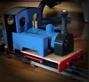
I will bescrive here the installation of the receiver in my LGB Rusty loco.

amd upload
I have to include into the loco the further parts:
- 1 Arduino Nano
- 1 L298N engine driver
- 4x 18650 batteries
- 1 5v regulator (indeed the L298N can't provide 5v if powered by more than 12v, and in our case we have 4*3.4v= 13.6)
- 1 NRF24L01
- 1 ON/OFF switch
- all the wiring plus the resistor for the voltage measurement
Openning of the loco:
You have to remove the 6 screws to remove the cabin, then the screws for the couplers and bumper. Finally the 2 screws in the forward part of the loco to remove the whole boiler.

amd upload

amd upload
Finally I removed the 4 screws to open the red cover where a big piece of lead is fitted

amd upload
amd upload
I have to include into the loco the further parts:
- 1 Arduino Nano
- 1 L298N engine driver
- 4x 18650 batteries
- 1 5v regulator (indeed the L298N can't provide 5v if powered by more than 12v, and in our case we have 4*3.4v= 13.6)
- 1 NRF24L01
- 1 ON/OFF switch
- all the wiring plus the resistor for the voltage measurement
Openning of the loco:
You have to remove the 6 screws to remove the cabin, then the screws for the couplers and bumper. Finally the 2 screws in the forward part of the loco to remove the whole boiler.
amd upload
amd upload
Finally I removed the 4 screws to open the red cover where a big piece of lead is fitted
amd upload


Re: DIY Arduino radio control for garden train
Here is how I have connected the L298N :
I have cut the boiler of the loco just under the red cover and removed a part of the lead to fit the L298N module in the created gap :

amd upload

amd upload
Wiring diagram :

amd upload
Connexions L298n to Arduino:
pin ENA ==> pin D5
pin IN1 ==> pin D4
pin IN2 ==> pin D3
pin ENB ==> jumper in place to power the light to maximum available voltage
pin IN3 ==> pin D6
pin IN4 ==> pin D7
Connexions L298n other :
pin +35v ==> + battery
pin GND ==> – battery and GND Arduino
pin 5v ==> pin 5v voltage regulator
2 pins OUT A ==> motor
2 pinss OUT B ==> light
jumper JMP1 removed to power the L298N logic circuit from the external 5v voltage regulator .
I have cut the boiler of the loco just under the red cover and removed a part of the lead to fit the L298N module in the created gap :
amd upload
amd upload
Wiring diagram :
amd upload
Connexions L298n to Arduino:
pin ENA ==> pin D5
pin IN1 ==> pin D4
pin IN2 ==> pin D3
pin ENB ==> jumper in place to power the light to maximum available voltage
pin IN3 ==> pin D6
pin IN4 ==> pin D7
Connexions L298n other :
pin +35v ==> + battery
pin GND ==> – battery and GND Arduino
pin 5v ==> pin 5v voltage regulator
2 pins OUT A ==> motor
2 pinss OUT B ==> light
jumper JMP1 removed to power the L298N logic circuit from the external 5v voltage regulator .
-
-steves-
- Administrator
- Posts: 2444
- Joined: Thu Jul 28, 2011 1:50 pm
- Location: Cambridge & Peterborough
Re: DIY Arduino radio control for garden train
That seems to fit really well after a bit of modification.
What software did you use to create the diagrams, they are really good?
What software did you use to create the diagrams, they are really good?
The buck stops here .......
Ditton Meadow Light Railway (DMLR)
Member of Peterborough and District Association
http://peterborough.16mm.org.uk/
Ditton Meadow Light Railway (DMLR)
Member of Peterborough and District Association
http://peterborough.16mm.org.uk/
Re: DIY Arduino radio control for garden train
Installation of nRF24L01 :
This module fits just under the chimney :

Here is the wiring diagram :

pin VCC ==> pin 3V3
pin GND ==> pin GND
pin CSN ==>pin D9
pin CE ==> pin D10
pin MOSI ==> pin D11
pin SCK ==> pin D13
pin MISO ==> pin D12
This module fits just under the chimney :
Here is the wiring diagram :
pin VCC ==> pin 3V3
pin GND ==> pin GND
pin CSN ==>pin D9
pin CE ==> pin D10
pin MOSI ==> pin D11
pin SCK ==> pin D13
pin MISO ==> pin D12
-
-steves-
- Administrator
- Posts: 2444
- Joined: Thu Jul 28, 2011 1:50 pm
- Location: Cambridge & Peterborough
Re: DIY Arduino radio control for garden train
Just downloading the 0.9.3b now
The buck stops here .......
Ditton Meadow Light Railway (DMLR)
Member of Peterborough and District Association
http://peterborough.16mm.org.uk/
Ditton Meadow Light Railway (DMLR)
Member of Peterborough and District Association
http://peterborough.16mm.org.uk/
Re: DIY Arduino radio control for garden train
Power supply :
The 4 batteries 18650 are installed in the cabin so I can easily access to remove them and charge them. The wires are going into the boiler via a hole that was originlly used for a small bulb.


The power supply wiring including the voltage divider with 2 resistors :

The 4 batteries 18650 are installed in the cabin so I can easily access to remove them and charge them. The wires are going into the boiler via a hole that was originlly used for a small bulb.
The power supply wiring including the voltage divider with 2 resistors :
Re: DIY Arduino radio control for garden train
[/quote]
Just downloading the 0.9.3b now Thank you
[/quote]
cool, after you can find on the internet the missing objects to complete the library.
Just downloading the 0.9.3b now
[/quote]
cool, after you can find on the internet the missing objects to complete the library.
Who is online
Users browsing this forum: No registered users and 7 guests