Building THORNAS - ADDING SOUND

A place where discussions are about 3D printing.
User avatar
philipy
Moderator
Moderator
Posts: 5098
Joined: Sun Jan 30, 2011 3:00 pm
Location: South Northants

Building THORNAS - ADDING SOUND

Post by philipy » Mon Oct 23, 2023 1:54 pm

In his thread Nolyn Valley Tramway, https://gardenrails.org/forum/viewtopic ... 3&start=80 Drew has shown his 0-4-0 ''Thornas'. Originally conceived as a push-along toy for his 2 y/o, based on Thomas the Tank Engine albeit an 0-4-0 not 0-6-0. He subsequently motorised it and along the way experimented with various modifications. Recently Drew kindly uploaded his stl's to our Print Files section and since it has always appealed to me, I jumped at the chance to download it and get stuck in.

The files contain a comprehensive set of expoded sketches and suggested build order.
Screenshot 2023-10-23 13.36.15.png
Screenshot 2023-10-23 13.36.15.png (78.67 KiB) Viewed 5435 times
When designing and building any 3d printed model, I always assemble the stl files into a vitual model on the computer to check for fit and any unplanned conflicts, etc, so the first thing I did was to import the stl's into Sketchup, one at a time.

Starting with the chassis there are two sideframes, two buffer beams and two spacers ( at either 32mm or 45mm spacing).
I decided that it would make life a lot easier and more accurate if the spacers were part of the buffer beam since that would fix the sideframes at exactly the right position, so I positioned them on the back of the beam and joined them together in Sketchup, saved it and printed them as one piece.

The sideframes printed easily and cleanly and when fixed to the buffer beam spacers should work well. However at this point I realised that there is nothing to keep them square, until I realised that the two-part motor bracket sits in the middle and will act as a centre spacer.

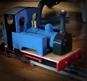
Somewhere at this point it dawned on me that that this loco is outside frame, although nothing in the instructions tells you and the photo's on Drew's thread are too dark below the footplate to see it.

I dislike having wheels and mechanisms trapped during the build, particularly with an outside frame loco, so I decided to screw fix one side of the chassis, a simple enough modification, using 6 x small self tappers, 2 each in the end spacers and two in the motor mount. Once I'm sure it is running sweetly, a drop of glue should lock everything in place.
IMG_0359.jpg
IMG_0359.jpg (252.11 KiB) Viewed 5435 times
This shows the frame assembled, but the motor mount not yet screwed in place. At this point I also realised that the axle holes are just 3mm diameter which fine for the axle itself but doesn't allow for a brass bush, much less a bearing. I should have done something about it before getting this far!
Philip

User avatar
drewzero1
Administrator
Administrator
Posts: 486
Joined: Fri Apr 21, 2023 4:35 pm
Location: WI, US

Re: Building THORNAS

Post by drewzero1 » Mon Oct 23, 2023 4:20 pm

It's so surreal to see my model in someone else's picture! (That's strange, don't remember taking that one! :lol: ) Excellent work so far, and I'm already seeing some "wish I'd thought of"s of which I'm sure there will be plenty.

I appreciate the feedback on the instructions. Not sure why I never considered to mention that it's outside frame, but there it is! I have some construction photos of my own that I was saving for a build thread (which I never got around to):
Counterclockwise from left: February, March, April 2023
thornas_development.jpg (301.77 KiB) Viewed 5422 times
I apologize also for the dark photos. I do most of my modeling late at night and I always forget to take pictures when the sun's out. Which reminds me, I have some pictures to take...

User avatar
philipy
Moderator
Moderator
Posts: 5098
Joined: Sun Jan 30, 2011 3:00 pm
Location: South Northants

Re: Building THORNAS

Post by philipy » Wed Oct 25, 2023 9:07 am

I couldn't find a source of the motor Drew used, available in a reasonable time, but I found a close alternative which had the same 25mm diameter. I did have a bit of a problem with the two-part motor mount which I couldn't get to both line up with the axle and sit between the frames. In the end I slightly redrew the side pieces to make them deeper but I'm not sure what the actual problem was since my motor is 25mm diameter, the same as the original.
As with the chassis frames, one side of the motor mount is glued and the other screwed to allow the mechanism to be dismantled if necessary.

Drew's instructions suggest using ply or plasticard for a running board but he does include an stl for a small cab floor with steps, and a mounting for an on/off switch. Instead I drew up a complete one piece footplate with a central cutout for the motor but included Drew's cab steps. Because I intend to position the switch in a different location, I omitted that mounting hole in the cab. The footplate includes two small cross strips at the ends, on the underside, to locate inside the buffer beams. The body prints will be glued to the footplate and the whole assemby screwed to the chassis.
Screenshot 2023-10-25 08.48.35.png
Screenshot 2023-10-25 08.48.35.png (91.09 KiB) Viewed 5357 times


The body consists of quite a few separate parts and the firebox, boiler and smokebox are three separate drawings. I could foresee a lot of work to get a smooth finish so I combined the three into one complete assembled stl and then resin printed it as one piece, but before doing so I redrew the smokebox door from scratch.
IMG_0356.jpg
IMG_0356.jpg (493.12 KiB) Viewed 5357 times


Drew did mention that he had used one from Thingiverse and although it's fine for a push-along toy train, it didn't look good enough to my eye, being flat fronted and angular.
Screenshot 2023-10-25 08.43.19.png
Screenshot 2023-10-25 08.43.19.png (170.75 KiB) Viewed 5357 times


Drew's design allows for 18650 lithium batteries to be housed in the side tanks, 2 each side, and he has incorporated shaped holders and brass contacts. I would rather use 6 x Low Self Discharge NiMh batteries, so I stripped out the inside of the tanks and constructed 2 x 3 cell packs using tagged batteries.
The three batteries don't quite fit inside the tanks vertically, so they are arranged in a triangle and slightly protrude sideways into the firebox/boiler, but can't really be seen
Because the NiMh's are shorter than 18650's that should leave enough room for a repositioned switch and the Rx and fuse, etc.
Screenshot 2023-10-25 08.58.16.png
Screenshot 2023-10-25 08.58.16.png (92.21 KiB) Viewed 5357 times
Philip

User avatar
drewzero1
Administrator
Administrator
Posts: 486
Joined: Fri Apr 21, 2023 4:35 pm
Location: WI, US

Re: Building THORNAS

Post by drewzero1 » Wed Oct 25, 2023 12:29 pm

Looking good! I like the improvements you've made. That smokebox door was actually one of mine, though the as-built Thornas' used a similarly crude one from Thingiverse (scaled up from an O-16.5 design). Yours looks much better!

I'm also not sure what's wrong with the motor mount but that was one piece I kind of rushed and meant to come back to later... I guess it's later now :oops:

User avatar
philipy
Moderator
Moderator
Posts: 5098
Joined: Sun Jan 30, 2011 3:00 pm
Location: South Northants

Re: Building THORNAS

Post by philipy » Wed Oct 25, 2023 1:56 pm

drewzero1 wrote: Wed Oct 25, 2023 12:29 pm
I'm also not sure what's wrong with the motor mount but that was one piece I kind of rushed and meant to come back to later... I guess it's later now :oops:
I had a kind of revelation an hour or so ago and I think I may have found a better answer. I know your motor is 25mm diameter but how long is it? (body + shaft). I'm printing a new motor mount as we speak and I'm 95% sure it will work for my motor but yours may or may not be too long.
Philip

User avatar
GTB
Driver
Driver
Posts: 1559
Joined: Sat Mar 05, 2011 2:46 pm
Location: Australia

Re: Building THORNAS

Post by GTB » Thu Oct 26, 2023 8:58 am

philipy wrote: Wed Oct 25, 2023 1:56 pm
drewzero1 wrote: Wed Oct 25, 2023 12:29 pm
I'm also not sure what's wrong with the motor mount but that was one piece I kind of rushed and meant to come back to later... I guess it's later now :oops:

I had a kind of revelation an hour or so ago and I think I may have found a better answer. I know your motor is 25mm diameter but how long is it? (body + shaft). I'm printing a new motor mount as we speak and I'm 95% sure it will work for my motor but yours may or may not be too long.
The gearbox of those '25D' gearmotors is 25mm dia., but the motor is usually 24.4mm. Not an issue if they are mounted to a bracket using the M3 tapped holes in the gearbox front plate as designed. Clamping them around the middle will have to account for the difference in diameters, or the motor may move around under load.

Graeme

User avatar
philipy
Moderator
Moderator
Posts: 5098
Joined: Sun Jan 30, 2011 3:00 pm
Location: South Northants

Re: Building THORNAS

Post by philipy » Thu Oct 26, 2023 11:40 am

GTB wrote: Thu Oct 26, 2023 8:58 am

The gearbox of those '25D' gearmotors is 25mm dia., but the motor is usually 24.4mm. Not an issue if they are mounted to a bracket using the M3 tapped holes in the gearbox front plate as designed. Clamping them around the middle will have to account for the difference in diameters, or the motor may move around under load.
Yes, agreed Graeme. Drew's clamp mount does work and holds it securely, but I had a problem lining it up with the axle visually since there is no means of positive location prior to fixing. I'm playing with a U-shaped bracket to use the 3mm tapped holes as you suggest, and with my motor it just goes in vertically, but I'm not sure how long Drew's motor is, so if its a tiny bit longer it probably won't fit and might have to be angled. Not a major issue either way but I just wanted to be aware.
Philip

User avatar
drewzero1
Administrator
Administrator
Posts: 486
Joined: Fri Apr 21, 2023 4:35 pm
Location: WI, US

Re: Building THORNAS

Post by drewzero1 » Thu Oct 26, 2023 3:59 pm

philipy wrote: Wed Oct 25, 2023 1:56 pm I had a kind of revelation an hour or so ago and I think I may have found a better answer. I know your motor is 25mm diameter but how long is it? (body + shaft). I'm printing a new motor mount as we speak and I'm 95% sure it will work for my motor but yours may or may not be too long.
Total length approx. 65mm. The upper and lower parts were split with a few mm gap between them so the screw tension could tighten on the motor, though a shim could be used around the motor if it's not enough. (Rubber could help dampen motor noise, though the motor I've used turned out to be quieter than expected.)

I did use the tapped holes on the end to secure the motor to the axle, but it looks like I forgot to include that part as well. :oops: :oops: Mine used a slit to allow it to be passed over the axle after assembly, but with your removable side frame yours may not need that. I'll see if I can find the part file for that and post it. (EDIT: I've found them and posted them with the other Thornas files, click here to view.)

Note that my axles are 3.175mm (1/8 inch) because metric brass stock isn't available locally.

User avatar
philipy
Moderator
Moderator
Posts: 5098
Joined: Sun Jan 30, 2011 3:00 pm
Location: South Northants

Re: Building THORNAS

Post by philipy » Sun Oct 29, 2023 7:59 am

Well I've been working behind the scenes as it were, these last few days.
Early on, Drew said to me that he had been trying to find a way of making the mchanism removable, and after several hours drawing and a short while with drills, saw and files, I think I've achieved it. :D

The U-shaped motor mounting bracket that Drew posted on Thursday was similar to one I had been playing with myself, but I've had a problem in that the bevel gears I had were too big to get between the inside frames. I've been reluctant to print gears because I wasn't convinced that they would stand up to much use, but in the end I've finally gone down that route and it does have the advantage that I printed one with a 4mm bore for the motor shaft and one with a 3mm bore for the driven axle.

So, the problem with a removable drive mechanism is locating it accurately and fixing it into the outside frames, since the axles have a bearing in the frames themselves. Eventually I realised that if the motor mounting bracket was outside of the wheels it could be made to fit snugly against the inside of the frames. From there it was a short leap to realise that the frame bearing could be printed as part of the bracket, not as part of the frame itself and that if the frame had a slot in it, that slot could be filled by a part printed on the motor bracket as well.
Screenshot 2023-10-28 12.50.43.png
Screenshot 2023-10-28 12.50.43.png (28.18 KiB) Viewed 5115 times
In hindsight I should have made the bracket a bit wider to get a fourth screw in, but I don't think it will matter.

Having drawn it up and printed it, a small amount of fettling had it neat and tidy and after half an hour or so I had the slots cut and the frame bearing bosses removed and it slid neatly into place from below. The mechanism then just requires some small screws into the frame to secure it. This also has the bonus that I can now glue the previously screwed sideframe and make a permanent job of it. :D
IMG_0366.jpg
IMG_0366.jpg (443.18 KiB) Viewed 5115 times
I think I'm going to reprint this side, with the cutout 'built in' and without all the extraneous screw holes - will be easier to reprint than mess about trying to fill all the holes!
Philip

User avatar
drewzero1
Administrator
Administrator
Posts: 486
Joined: Fri Apr 21, 2023 4:35 pm
Location: WI, US

Re: Building THORNAS

Post by drewzero1 » Sun Oct 29, 2023 8:11 am

Looks great! If you use a similar notch setup for the unpowered axle, both could be removed for maintenance or replacement. I might have to modify the new one I've been building to allow for that possibility. How long is the motor you're using? Mounting it vertically like that should give you a lot more room for ESC/receiver/sound card, or more battery space.

User avatar
philipy
Moderator
Moderator
Posts: 5098
Joined: Sun Jan 30, 2011 3:00 pm
Location: South Northants

Re: Building THORNAS

Post by philipy » Sun Oct 29, 2023 9:15 am

The motor+gearbox is 42mm o/a plus the shaft at about 10mm.

I did think about doing the same for the unpowered axle, but once it is all together and running properly, I can't see that that axle would need to be removed very often if at all, ever. Having it all flopping about unrestrained would potentially put a lot of strain on the coupling rod/crank joints so I think if I ever needed to remove the motor etc I'd undo the coupling rods anyway.

Do you want my stl for the notched frame? Yu are more than welcome to it.
Philip

User avatar
philipy
Moderator
Moderator
Posts: 5098
Joined: Sun Jan 30, 2011 3:00 pm
Location: South Northants

Re: Building THORNAS

Post by philipy » Sun Oct 29, 2023 1:08 pm

Things are moving on now that I'm happy with how the chassis is going.

I have actually been working on the various body parts along the way and started assembling them this morning,

I printed the cab back and bunker as two separate pieces, having split Drew's original stl. I felt that this would give a better finish to the flat surfaces, although subsequently I had to fill and smooth the joint lines.

I started from the back and glued the bunker/cab back to the footplate, and then next the two tanks were also stuck to the footplate. The reason for this sequence is that the cab steps are part of the footplate so any slight misalignment would be obvious and the top of the steps gave a nice fixed starting point in both directions.

The cab front was fairly plain but of course I complicated it! There was no way of accurately locating the firebox, so I used the back edge of the firebox drawing to create a raised flange on the cab front that the box itself could fit around. My modified motor location very slightly protrudes back into the cab so I changed the size/shape of the cutout in Drew's drawing to accomodate the motor. Also, separately I drew up and printed a rudimentry backhead to add some detail/interest in the cab, and hollowed it out to sit round the motor.
IMG_0385.jpg
IMG_0385.jpg (5.77 MiB) Viewed 5067 times
Once all the glue joints are firmly set....[ to be continued!]
Philip

User avatar
ge_rik
Administrator
Administrator
Posts: 6580
Joined: Sun Oct 25, 2009 10:20 pm
Location: Cheshire
Contact:

Re: Building THORNAS

Post by ge_rik » Sun Oct 29, 2023 4:37 pm

Coming together well, Philip.
Be interested to see how it looks and performs.

Rik
------------------------
Peckforton Light Railway - Blog Facebook Youtube

User avatar
drewzero1
Administrator
Administrator
Posts: 486
Joined: Fri Apr 21, 2023 4:35 pm
Location: WI, US

Re: Building THORNAS

Post by drewzero1 » Sun Oct 29, 2023 8:51 pm

ge_rik wrote: Sun Oct 29, 2023 4:37 pm Coming together well, Philip.
Be interested to see how it looks and performs.

Rik
Me too! A bit nervous to see how it stacks up against 'real' model locos and stock... everything I have in this scale is scratchbuilt so I have no idea how it will compare!

User avatar
philipy
Moderator
Moderator
Posts: 5098
Joined: Sun Jan 30, 2011 3:00 pm
Location: South Northants

Re: Building THORNAS

Post by philipy » Mon Oct 30, 2023 6:33 am

drewzero1 wrote: Sun Oct 29, 2023 8:51 pm Me too! A bit nervous to see how it stacks up against 'real' model locos and stock... everything I have in this scale is scratchbuilt so I have no idea how it will compare!
I must admit that it didn't really occur to me to check the 'scale' of a non-prototype model, until yesterday.
In an odd moment I looked out my 3d drawings of various loco crew, trying to decide if one of them will do when the time comes. That was when I discovered that the loco appears to be about 12% under sized compared to a 95mm high/6ft tall, 16mm driver figure. The tallest figure that will fit in the cab of Thornas is about 85mm high.

It doesn't really matter for this model, I also have some small wagons that I've acquired over the years from various sources, but if I had realised in time, I'd simply have scaled everything up by 12% from the beginning.
Philip

User avatar
GTB
Driver
Driver
Posts: 1559
Joined: Sat Mar 05, 2011 2:46 pm
Location: Australia

Re: Building THORNAS

Post by GTB » Mon Oct 30, 2023 9:10 am

philipy wrote: Mon Oct 30, 2023 6:33 am The tallest figure that will fit in the cab of Thornas is about 85mm high.
That makes the cab about the same height as a Kerr Stuart Skylark. The TVT engineer is 85mm tall and he just fits in the Skylark cab. I wouldn't worry too much, Skylarks weren't alone in having low cabs.

Anyway, the average male Brit was nowhere near 6' during the steam era, a steam loco driver was probably doing well to be 5'6" (88mm in 16mm/ft scale).

Graeme

User avatar
philipy
Moderator
Moderator
Posts: 5098
Joined: Sun Jan 30, 2011 3:00 pm
Location: South Northants

Re: Building THORNAS

Post by philipy » Mon Oct 30, 2023 9:27 am

GTB wrote: Mon Oct 30, 2023 9:10 am
philipy wrote: Mon Oct 30, 2023 6:33 am The tallest figure that will fit in the cab of Thornas is about 85mm high.
That makes the cab about the same height as a Kerr Stuart Skylark. The TVT engineer is 85mm tall and he just fits in the Skylark cab. I wouldn't worry too much, Skylarks weren't alone in having low cabs.
Thanks Graeme. I hadn't realised that Skylark was that low, either.
Philip

User avatar
GTB
Driver
Driver
Posts: 1559
Joined: Sat Mar 05, 2011 2:46 pm
Location: Australia

Re: Building THORNAS

Post by GTB » Mon Oct 30, 2023 10:12 am

philipy wrote: Mon Oct 30, 2023 9:27 am Thanks Graeme. I hadn't realised that Skylark was that low, either.
Consider the Groudle Glen Bagnalls, which are probably right up your alley. 2' gauge, but the cab is so small the driver has to sit to fit..........

Graeme

User avatar
steelskeg
New User
New User
Posts: 1
Joined: Mon Aug 28, 2023 11:39 am

Re: Building THORNAS

Post by steelskeg » Mon Oct 30, 2023 11:03 am

philipy wrote: Sun Oct 29, 2023 1:08 pm Things are moving on now that I'm happy with how the chassis is going.

I have actually been working on the various body parts along the way and started assembling them this morning,

I printed the cab back and bunker as two separate pieces, having split Drew's original stl. I felt that this would give a better finish to the flat surfaces, although subsequently I had to fill and smooth the joint lines.

I started from the back and glued the bunker/cab back to the footplate, and then next the two tanks were also stuck to the footplate. The reason for this sequence is that the cab steps are part of the footplate so any slight misalignment would be obvious and the top of the steps gave a nice fixed starting point in both directions.

The cab front was fairly plain but of course I complicated it! There was no way of accurately locating the firebox, so I used the back edge of the firebox drawing to create a raised flange on the cab front that the box itself could fit around. My modified motor location very slightly protrudes back into the cab so I changed the size/shape of the cutout in Drew's drawing to accomodate the motor. Also, separately I drew up and printed a rudimentry backhead to add some detail/interest in the cab, and hollowed it out to sit round the motor.

IMG_0385.jpg

Once all the glue joints are firmly set....[ to be continued!]
That sounds like a great progress update! It's smart to split the cab back and bunker for a better finish, even if it meant some extra work. Starting from the back and working your way forward seems like a good strategy for alignment. Adding those extra details to the cab front and accommodating the motor shows your attention to detail. Keep up the good work!
Dive into the realm of cutting-edge Motor technology, where power meets efficiency in our latest innovations.

User avatar
philipy
Moderator
Moderator
Posts: 5098
Joined: Sun Jan 30, 2011 3:00 pm
Location: South Northants

Re: Building THORNAS

Post by philipy » Mon Oct 30, 2023 1:15 pm

steelskeg wrote: Mon Oct 30, 2023 11:03 am
Keep up the good work!
Thanks.
I see you are fairly new around here, how about popping over to the Introduction section and tell us a bit about yourself?
Philip

Post Reply

Who is online

Users browsing this forum: No registered users and 5 guests