I came up with an idea part way through my wild rose project and wondered now I have DRO's on my mill and lathe, would I be any better at getting things any more accurate. So I took the stock below and started tinkering.
But what will it be???


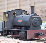

Sounds like a fun project you have on there, looking forward to seeing some pictures on the forum?Oily Rag wrote: Sun Jun 30, 2019 8:15 pm I will be interested to see what this does turn out to be. Besides all the workshop stuff I have added another little project to my list as well. There has been a short series in Model Engineer about a simple and realatively crude "Dairy Engine". An oscillater with a vertical boiler, meths fired on a little trolley. I found a Unit Engine kit lurking as you do, ideal for a bit of fun. So I don't have to make the engine, just a pulley and a pot boiler. I even found some old raw Mamod flywheel castings I bought from them years ago. These will make the wheels I hope once fettled and machined.
Have fun!!!
I will be interested to see how you get on with the DROs, i have no plans myself but will look forward to seeing how you progress.


 It's somewhere between a GRS chassis and an Essel chassis, based on neither but has similarities to both. It seems to be a success, so with that in mind, I will probably try an 0-6-0 chassis at some point with a drive crank, aim high hey, lol If that's a success then I guess I can build myself any size electric chassis depending on what body I want to build it for.





LOL, thanks Rod. The body for this one will likely be a Whisbech style tram as I have always fancied one of those. I part done the plans for one a while back, I just need to finish the plans off and then start a build, but in wood, now that will be interesting as it's quite some time since I worked in wood, I think the last time was when I was into RC boats in my teenage years, lolFWLR wrote: Mon Jul 01, 2019 7:38 am Thats actually a very nice job Steve. Like the way you have done the wheels to be gauge adjustable. Well done mate. Now waiting for the body to be built episode....


 Looking forward to seeing it develop....
Well done. I've been wondering how long it would take you to realise that the skills to build a rolling steam chassis were the same as those to build one that runs on elektrickery.........-steves- wrote: Sun Jun 30, 2019 9:01 pm So here it is, a couple of days in the shed and I have come up with a working chassis.

 )
) Ian. I think you have taken my words a little too literally, I am of course aware that even a 4mm drill bit does not drill a 4mm hole, and that under a microscope actually looks nothing like a round hole, perfection really doesn't exist, however the word does. I think the point I was trying to make that making a drilled chassis side, drilling corresponding con rods and cranks drilled right, takes small tolerances between working and not working. I have tried by hand to dot punch and drill on a pillar drill having marked everything out and to say it needed "some fettling" afterwards is an understatement, big files were required all over the place, that much that the bearing actually moved inside the hole I have to open it up so much. Suffice to say that attempt actually went in the bin, but that was quite some time ago that I tried that. The chassis that I made above required no fettling of con rods, wheels, bearing, cranks etc, it all ran when just bolted together, I was as surprised as anyone, but also very pleasedOily Rag wrote: Tue Jul 02, 2019 9:34 am Hi Steve,
I would like to point that there is no such thing as "absolute perfection". ALL engineering works within tolerance band widths. For example take computer disc drives, the read/write heads actually fly, they are aerodynamic and even when hard disc drive discs were 14" (356MM) diameter the heads flew nanometres above the surface of the disc. The Queens Award for Technological Achievement citation for that project read something along the lines of: " this has achieved the equivalent of flying Concorde at Mach 2 some 12" (300MM) above a ploughed field". Every component in that drive had a tolerance bandwidth. I know I was there and have the gold cufflinks as testament. I spent much of my time as did every other designer and engineer on the project checking what were called tolerance stacks for each sub assembly and assembly. Machining of base castings was done under extreme controlled conditions down to a temperature (within a small bandwidth) and that had to be accounted for. Humans were not allowed inside the controlled area once a machine programme had started yet they still had tolerances!
It has been said over many years in the model engineering field that the worst steam engine builders are toolmakers, not a derogatory comment at all. Because these guys always strived for perfection and that was never the intention of the original masters of the art.
Its a contentious issue but it all comes down in the end to experience, gathered in depth knowledge of the subject and most of all designing out the problems at the paper stage and making allownces for adjustment as the model comes together. Stan Bray a well known author and builder actually uses and advocates eccentric bushes in his motion rods so that adjustments can be made. He is certainly no slouch look at his portfolio from the simple to the complex. You can chnge your "absolute perfection" by picking the thing up with your warm hands or moving from shed to central heated lounge and its enough to seize a mechanism.
The operative phrase is 'if you want accurate location'...... Which is what the teacher was getting at.tom_tom_go wrote: Mon Jul 01, 2019 10:45 pm I always drill pilot holes but Graeme mentioned he has been taught otherwise?
One can't ask for better results than that......-steves- wrote: Tue Jul 02, 2019 3:40 pm The chassis that I made above required no fettling of con rods, wheels, bearing, cranks etc, it all ran when just bolted together, I was as surprised as anyone, but also very pleased
As Ian said, a very good question. I spent ages trying to work this one out, I thought about rotary tables and the like, then realised that a simple solution was best. I took a square bit of brass, drill through it from one end to the other at the thickness of the axle, then on the side drilled a hole and tapped it for a grub screw. Simple pop the axle in sticking out of both ends, mill one end, take it out, turn it around 90 degrees and mill the other end, simple and works perfectly every time. The only down side is you need one tool for each size of axle, but no real biggy.GTB wrote: Wed Jul 03, 2019 1:01 pmOne can't ask for better results than that......-steves- wrote: Tue Jul 02, 2019 3:40 pm The chassis that I made above required no fettling of con rods, wheels, bearing, cranks etc, it all ran when just bolted together, I was as surprised as anyone, but also very pleased
I forgot to ask earlier. You mentioned you milled flats on the axles to set the quartering on the cranks. How did you machine those?
Regards,
Graeme
I hope the post above clarifies how I have been doing it, really simple but it worksOily Rag wrote: Wed Jul 03, 2019 2:42 pm That's an interesting question Graeme. I have often wondered about milling grub screw flats for flycranks. I drew the conclusion that under the circumstance of them NOT having to be exactly 90 deg (R.H. by convention leading), one axle could be milled both ends using the rotary table, accurate enough I would think but only mill one flat on the other axle leaving the remaining flycrank to be set to give best running. The other conclusion I came to was that in future all flycranks and the like mrequiring securing to round shafting of any sort would have two grub screws set about 90deg apart unless there was suitability for a roll pin.
The other way is to leave the axles over long, centre the outer end and mill the flats indexing along, then machining the axle to length.


You're on a roll.........-steves- wrote: Wed Jul 10, 2019 1:20 am A bit more time on the shed, the pictures do not show the con rods, but I made those as well and tried it as just the 6 wheels and again, works perfectly, no fettling required.


Users browsing this forum: No registered users and 10 guests