SEBC 2016 Modular Layout

A place for the discussion of garden railways and any garden style/scale portable and/or indoor layouts
User avatar
Dwayne
Trainee Driver
Trainee Driver
Posts: 681
Joined: Mon Jul 04, 2011 12:15 am
Location: Oklahoma City

SEBC 2016 Modular Layout

Post by Dwayne » Sat Jul 09, 2016 7:09 pm

A slight derailing of my time and effort has gone into play as of a few days ago. I am a member of the SEBC (Seven Eights Breakfast Club) here in Oklahoma City which consists of three 1:13n2 modelers - Bill Martinsen, David Miller and myself.

A few months ago we were approached by the Central Oklahoma Garden Railway Society (COGRS) and asked if we would be interested in building a 7/8ths scale display module for the annual Oklahoma City train show that occurs in December. After some discussion the three of us accepted and submitted a track plan and graphic rendering of what we would be building.

Image

Image

David drew up the plans to full scale and mounted it to a 3/4" birch ply substrate which he delivered to me this past Wednesday. My primary contribution will be hand laying the code 250 aluminum rail. Included will be two switches, four track crossings and a small four inch turntable. As can be seen the track plan allows for future expansion.

Trackwork is non-powered which means that my little RC/battery Davenport critter will be the primary motive power. If I have the time I'm going to consider adding RC to my live steamer so that it too can be run.

David will be the primary builder of the structures and scenery.

Bill is a fantastic rolling stock scratchbuilder and will thus supply the bulk of the freight cars.

I'll post updates as and when they happen. :)

User avatar
MDLR
Driver
Driver
Posts: 4027
Joined: Thu Jan 15, 2009 10:38 pm
Location: Near Ripley, Derbyshire, UK
Contact:

Post by MDLR » Sat Jul 09, 2016 8:36 pm

As somebody who has built something similar (along with John Rogers) I look forward to seeing this grow. Are you going for detachable buildings?
Brian L Dominic
Managing Director
Flagg Fluorspar Co
www.mdlr.co.uk/ff.html

User avatar
Peter Butler
Driver
Driver
Posts: 5258
Joined: Sun Sep 09, 2012 10:33 pm
Location: West Wales

Post by Peter Butler » Sat Jul 09, 2016 9:16 pm

Dwayne, that is just brilliant! I think the plan is interesting enough to attract a lot of attention at shows with plenty of scope to make attractive and functional structures. I have been tempted myself to make a small layout to show small stock, but that would mean building everything myself and taking me away from my garden railway, so.... non-starter.
However, it would only take someone to mention a 'Breakfast Club' and I could easily be persuaded!
The best things in life are free.... so why am I doing this?

User avatar
Dwayne
Trainee Driver
Trainee Driver
Posts: 681
Joined: Mon Jul 04, 2011 12:15 am
Location: Oklahoma City

Post by Dwayne » Sat Jul 09, 2016 10:02 pm

MDLR:118894 wrote:As somebody who has built something similar (along with John Rogers) I look forward to seeing this grow. Are you going for detachable buildings?
Brian, yes... buildings will be detachable for ease of transport and minimization of potential damage. The layout's size enables it to be fit in the back of David's Toyota pickup along with a planned base that it will rest upon at a height of about 42" (eye level for children).

Peter Butler:118895 wrote:Dwayne, that is just brilliant! I think the plan is interesting enough to attract a lot of attention at shows with plenty of scope to make attractive and functional structures. I have been tempted myself to make a small layout to show small stock, but that would mean building everything myself and taking me away from my garden railway, so.... non-starter.

However, it would only take someone to mention a 'Breakfast Club' and I could easily be persuaded!
Peter, this is a first for us doing a collaborative build as in 'indoor' layout. Individually none of us are inclined towards doing something like this but as a small group it appealed to us and the possibility of giving our scale some exposure.

It's pure fluke that there are three of us in our informal club. We are members of the SE Lounge (a 7/8ths dedicated forum) and decided to meet in person for breakfast about a year ago and somehow the name came up and it stuck. We're in agreement that the three of us probably comprise the highest concentration of 7/8ths modelers in one particular area within the vast expanse of the universe. :lol:

User avatar
MDLR
Driver
Driver
Posts: 4027
Joined: Thu Jan 15, 2009 10:38 pm
Location: Near Ripley, Derbyshire, UK
Contact:

Post by MDLR » Sat Jul 09, 2016 10:53 pm

Dwayne:118897 wrote:Brian, yes... buildings will be detachable for ease of transport and minimization of potential damage. The layout's size enables it to be fit in the back of David's Toyota pickup along with a planned base that it will rest upon at a height of about 42" (eye level for children).
Beware of The Poking Fingers................. I actually found building the whole thing into a box totally eliminated damage both in transit and in store - also, it never gets dusty.....................
Brian L Dominic
Managing Director
Flagg Fluorspar Co
www.mdlr.co.uk/ff.html

User avatar
andymctractor
Trainee Driver
Trainee Driver
Posts: 705
Joined: Fri Feb 01, 2013 12:03 am
Location: Suffolk, UK
Contact:

Post by andymctractor » Sun Jul 10, 2016 6:56 pm

MDLR:118898 wrote:Beware of The Poking Fingers................. I actually found building the whole thing into a box totally eliminated damage both in transit and in store - also, it never gets dusty.....................
I think transporting it in the back of a pick up in Oklahoma might test the 'never gets dusty' theory. :shock:

Good luck
Regards
Andy McMahon

If it moves, salute it.  If it doesn't move, paint it. (RN sailors basic skills course 1968)

User avatar
Dwayne
Trainee Driver
Trainee Driver
Posts: 681
Joined: Mon Jul 04, 2011 12:15 am
Location: Oklahoma City

Post by Dwayne » Mon Jul 11, 2016 12:21 am

Began working on the SEBC module yesterday. First thing on the agenda was to cut a whole in the layout board.

Image

Then take one 4 inch outdoor French drain grate and one 4 inch cap...

Image

Combine them in the hole and position...

Image

Then add a solid piece of acrylic to the grate, trim and add initial color..

Image

Add some rails and bolt them down with brass hardware...

Image

And then loosely fit into the layout board to ensure that the rails index properly when rotated...

Image

Then call it a day. :D

User avatar
philipy
Moderator
Moderator
Posts: 5114
Joined: Sun Jan 30, 2011 3:00 pm
Location: South Northants

Post by philipy » Mon Jul 11, 2016 5:40 am

That is very neat, Dwayne, I like that a lot.
Philip

User avatar
MDLR
Driver
Driver
Posts: 4027
Joined: Thu Jan 15, 2009 10:38 pm
Location: Near Ripley, Derbyshire, UK
Contact:

Post by MDLR » Mon Jul 11, 2016 4:37 pm

andymctractor:118902 wrote:I think transporting it in the back of a pick up in Oklahoma might test the 'never gets dusty' theory. :shock:
I think it would - I was thinking more on the lines of storing it in my garage!
Brian L Dominic
Managing Director
Flagg Fluorspar Co
www.mdlr.co.uk/ff.html

User avatar
Soar Valley Light
Driver
Driver
Posts: 1453
Joined: Sun Dec 08, 2013 5:18 pm
Location: North West Leicestershire

Post by Soar Valley Light » Mon Jul 11, 2016 8:36 pm

Beautiful job Dwayne. I love the holding down bolt detail on teh rails. :D
"Smith! Why do you only come to work four days a week?
"'cause I can't manage on three gaffer!"

User avatar
Dwayne
Trainee Driver
Trainee Driver
Posts: 681
Joined: Mon Jul 04, 2011 12:15 am
Location: Oklahoma City

Post by Dwayne » Tue Jul 12, 2016 3:58 am

Soar Valley Light:118925 wrote:Beautiful job Dwayne. I love the holding down bolt detail on teh rails. :D
Thanks Andrew. Since I'm a 10 foot modeler (if it looks good from 10 feet it's good enough) building this module is a new dimension for me as I realize it will be viewed up close.

The turntable in the photo below is the source of inspiration.

Image

jim@NAL
Driver
Driver
Posts: 1115
Joined: Sun Sep 23, 2012 11:01 am
Location: haverhill suffok

Post by jim@NAL » Tue Jul 12, 2016 9:24 pm

this is ace cant wait too see more

User avatar
Peter Butler
Driver
Driver
Posts: 5258
Joined: Sun Sep 09, 2012 10:33 pm
Location: West Wales

Post by Peter Butler » Tue Jul 12, 2016 9:43 pm

jim@NAL:118946 wrote:this is ace cant wait too see more
I agree Jim, this is what I need to inspire me to build an exhibition layout in 16mm. Perhaps when (if) the garden railway gets anywhere near completion?
The best things in life are free.... so why am I doing this?

User avatar
Soar Valley Light
Driver
Driver
Posts: 1453
Joined: Sun Dec 08, 2013 5:18 pm
Location: North West Leicestershire

Post by Soar Valley Light » Wed Jul 13, 2016 8:11 pm

That's fascinating Dwayne. The rail weight on the table is much less than that running up to it. I'm guessing that is because the table is older than its surroundings. I'd say the rail is 20 or 25lb on the table and 35lb in the plain line. Any idea where it is?

Andrew
"Smith! Why do you only come to work four days a week?
"'cause I can't manage on three gaffer!"

User avatar
Dwayne
Trainee Driver
Trainee Driver
Posts: 681
Joined: Mon Jul 04, 2011 12:15 am
Location: Oklahoma City

Post by Dwayne » Thu Jul 14, 2016 2:59 am

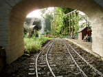
Soar Valley Light:118954 wrote:That's fascinating Dwayne. The rail weight on the table is much less than that running up to it. I'm guessing that is because the table is older than its surroundings. I'd say the rail is 20 or 25lb on the table and 35lb in the plain line. Any idea where it is?

Andrew
Andrew, I did notice the different rail weights as well. An interesting feature although not one I'm replicating. As for the location of this little turntable that I don't know. I just happened to have the photo in my collection from years ago and that information wasn't something I noted.

The past few evenings I've been working a bit on the layout. Decided to tackle the most complicated track feature first which are the two switches. The curved switch will have 'fixed points' (the closure rails and frog guard rails are one) and the shorter straight switch will use 'hinged points' (closure rails are hinged at the frog). I considered making the two separate but decided to built as one unit more or less.

Adding to the complexity of the switches is the close proximity of the diamond crossing (level junction). Having never built one of these before I spent a few hours looking online for some decent photos that show how they are fabricated, held together and the placement of the ties beneath. I realized quickly that I'll have to use rail plates/brackets along with brass nuts & bolts to keep these things together.

Image

I'm thinking I should have the two switches and the first crossing completed by this weekend. Afterwards the remainder should be much easier and more quickly installed. The rail that is outside of the buildings will be spiked down with 3/8" Micro Engineering spikes for appearance that I had on hand. The rail that will be inside the buildings will be spiked using the 5/8" x 19 nails I also use on my outdoor layout since the 1/4" thick building base is far to dense to push the ME spikes into without them bending since the rail is being attached directly to the building bases. I'm thinking that David plans to add either wood flooring or faux concrete around the interior rails giving them a flush, recessed appearance level with the floor itself so the oversized outdoor nails won't be seen.

BTW, the ties we're using came from David's old yard fence that had seen years of natural aging. He cut each tie to 4.25 - 4.50 inches long and 1/4" thick. I'm attaching these to the layout board using Gorilla PVA wood glue. Because the module replicates a flat industrial setting we felt that there wasn't really a need for the typical raised roadbed profile.

All in all this is turning out to be a track laying challenge but I'm having fun with it nonetheless. Truly a collaborative effort for the three of us. :)

User avatar
Soar Valley Light
Driver
Driver
Posts: 1453
Joined: Sun Dec 08, 2013 5:18 pm
Location: North West Leicestershire

Post by Soar Valley Light » Fri Jul 15, 2016 9:36 pm

Hi Dwayne,

I'm looking forward to seeing some more of your track laying and in particular the turnout construction. You've certainly got some challenges there!

Flat crossings are always a challenge. The famous one at Newark is just off our patch at work. It's where one of our secondary lines crosses the East Coast Mainline on the flat and it's a constant nightmare to maintain. It's much better now that cast maganese components are used but when it was a series of built up (bolted together) crossing units it was a real challenge. I'm sure you will do better with yours. Timbering S&C is a challenge at any time but in things like obtuse crossings it's a real art form!

Andrew
"Smith! Why do you only come to work four days a week?
"'cause I can't manage on three gaffer!"

User avatar
MDLR
Driver
Driver
Posts: 4027
Joined: Thu Jan 15, 2009 10:38 pm
Location: Near Ripley, Derbyshire, UK
Contact:

Post by MDLR » Sat Jul 16, 2016 8:53 pm

It's quite nice that since the construction of the Newark by-pass, what was once a railway feature "stuck in the middle of nowhere" is now overlooked by the road.

See https://goo.gl/maps/GRSFrD7Nr352 for a map.
Brian L Dominic
Managing Director
Flagg Fluorspar Co
www.mdlr.co.uk/ff.html

User avatar
Dwayne
Trainee Driver
Trainee Driver
Posts: 681
Joined: Mon Jul 04, 2011 12:15 am
Location: Oklahoma City

Post by Dwayne » Sun Jul 17, 2016 2:44 am

Brian, I checked out the crossing you posted to on Google maps. Always interesting to see ya'lls neck of the woods. It's hard to imagine that there 51 million of you folk crammed on an island that is only 1.3 times larger than the state of Oklahoma and with our population of only 3.78 million.

---

Today I worked on the module for a few hours before my back began to ache (the result of a vehicle accident a couple of weeks ago).

Image

In those hours I was able to fasten ties to the layout board and install a fair amount of rail to the ties. I was given several six foot long sections of tie material that I cut to size depending on it's location beneath the switches.

Getting the joints where one rail meets another at the crossing required some filing with a small flat file and much test fitting. Still remaining to be done are the inner rails of the crossing. Originally I anticipated having to fabricate brackets to keep these smaller segments of rail in place but I think that I should be able to forego that work and keep all the components in place with just spikes based on the way I laid out the ties beneath the crossing.

Before calling it a day I began assembling the larger curved switch which I hope to complete tomorrow. Then I'll move onto the smaller switch.

All in all it's starting to take shape. In a best case scenario I hope to have all the rail completed by next weekend before turning it over to fellow SEBC member Dave who is working on the buildings.

User avatar
LNR
Driver
Driver
Posts: 1548
Joined: Sat Feb 27, 2016 5:26 am
Location: Australia

Post by LNR » Sun Jul 17, 2016 7:43 am

Gee! Dwayne, your rail bender must be getting a fair bit of use. Nice fair curves (and plenty of them!) I think your a closet per-way man at heart. One thing I like about really small layouts, is you get the chance to finish every nook and cranny with the necessary detail (says he who has never finished any of his layouts completely).
Grant.

User avatar
philipy
Moderator
Moderator
Posts: 5114
Joined: Sun Jan 30, 2011 3:00 pm
Location: South Northants

Post by philipy » Sun Jul 17, 2016 8:19 am

Dwayne:118995 wrote:It's hard to imagine that there 51 million of you folk crammed on an island that is only 1.3 times larger than the state of Oklahoma and with our population of only 3.78 million.
Actually Dwayne, the latest population figures for the UK are somewhere around 65million, not 51mill!

P.S I do like your track laying :)
Philip

Post Reply

Who is online

Users browsing this forum: No registered users and 3 guests