2015 First Run

Anything related to the garden railway world that is not catered for in another board
Post Reply
Gralyn

2015 First Run

Post by Gralyn » Sun Jan 04, 2015 6:52 pm

I had the first run on the Overdale Valley Light Railway today. It was to try out a pair of Newquida bogie wagons after regauging from 45mm to 32mm.
Image
and

Image

Two short Videos both show that there is still a little work to do checking the back to back measurements as both wagons came off the track without any noticeable reason. Both wagons were ballasted but I think the ballast needs to be on the bogies rather than in the wagon
http://youtu.be/9z6QqbsintU
http://youtu.be/hZ3vji-F984

MDLR

Post by MDLR » Sun Jan 04, 2015 7:36 pm

It's interesting how critical back-to-back measurements can be: I had an IP Engineering 4 wheel coach which would NOT stay on the track at certain points on the Butterley circuit. I checked the BTB with my trusty Roundhouse gauge, only to find that the wheels were less than a millimetre too far apart (ie wide to gauge). Some gentle work with pliers (to detach one axlebox from the solebar) and hammer (to correct the BTB) resulted in a coach that now runs very happily!

User avatar
Soar Valley Light
Driver
Driver
Posts: 1490
Joined: Sun Dec 08, 2013 5:18 pm
Location: North West Leicestershire

Post by Soar Valley Light » Sun Jan 04, 2015 7:49 pm

It's an incredibly critical dimension in 12" to the foot scale so likely to be even more so when scaled down.

Wide back to back pushes the flanges harder against the gauge faces of the rails. As the flange is inclined on the face that meets the rail this force will naturally lead it to climb. With no suspension of any sort our vehicles will naturally 'rock' a great deal more than the prototype. It wouldn't take much of a rock, on a wheelset already climbing the rail, to lift the flange clear of the rail head and allow the vehicle to run into derailment.

This problem is even worse on the crossing noses of turnouts where such a situation will be highly likely to result in the flange going the wrong side of the crossing nose.

It amazes me that no one has ever developed compensation or even full blown springing in 16mm scale models. It's used quite successfully in Scalefour, it would make even more difference in 16mm. Although the effects would be very minimal it would be enough to prevent at least some derailments of this type.

Andrew
"Smith! Why do you only come to work four days a week?
"'cause I can't manage on three gaffer!"

MDLR

Post by MDLR » Sun Jan 04, 2015 7:59 pm

Soar Valley Light:107199 wrote:It amazes me that no one has ever developed compensation or even full blown springing in 16mm scale models.
It has, and some kits do have it, but you have to remember why many of us ended up modelling in this scale. I always tell people that I model in 16mm so that if I drop a piece on the floor, I can (a) see it and (b) pick it up again, which might cause a problem with sprung axleboxes and fully compensated underframes!

User avatar
Peter Butler
Driver
Driver
Posts: 5689
Joined: Sun Sep 09, 2012 10:33 pm
Location: West Wales

Post by Peter Butler » Sun Jan 04, 2015 8:38 pm

On some of my stock I sometimes, although not always, us a sort of compensation. In the first picture I have made up two identical units to hold the wheels and axles. On the finished model one of these is fixed to the underside of the truck, the other has a small brass tube attached in its centre line on top of the unit running from back to front. This is then fixed to the vehicle with a wire threaded through the tube and the unit allowed to tip by a small amount left and right. A spacer equal to the additional height of the tube should be added to the fixed unit to keep the vehicle level.

Image

The second picture shows the two units attached to the undercarriage separate from the chassis rail so movement is not restricted. It only needs movement of say 2mm to allow all wheels to stay in contact with the rails at all times.

Image
The best things in life are free.... so why am I doing this?

MDLR

Post by MDLR » Sun Jan 04, 2015 8:46 pm

Cunning!

User avatar
Soar Valley Light
Driver
Driver
Posts: 1490
Joined: Sun Dec 08, 2013 5:18 pm
Location: North West Leicestershire

Post by Soar Valley Light » Sun Jan 04, 2015 10:05 pm

Hi Guys,

I knew if I made a bold statement it would produce some comment! :D

Peter,

Your system is very similar to the compensation system used in scalefour. I'm sure it minimises the number of derailments on your line. I shall investigate something similar myself when I get round to rolling stock construction. It will be interesting to see how the various kits are suited to accepting such an arrangement.

I see Brian's point about keeping things simple completely but like all things in modelling - each to his own!

Here's to keeping on the straight and narrow - no matter how we do it!

Andrew
"Smith! Why do you only come to work four days a week?
"'cause I can't manage on three gaffer!"

mightymax

Post by mightymax » Sun Sep 13, 2015 3:47 am

Love the look of that little engine. Where did it come from and what powers it?

User avatar
ge_rik
Administrator
Administrator
Posts: 7865
Joined: Sun Oct 25, 2009 10:20 pm
Location: Cheshire
Contact:

Post by ge_rik » Sun Sep 13, 2015 7:42 am

Another really elegant solution, Peter. I must try something similar on a couple of wagons which have a longer wheelbase and sometimes struggle over my rather poorly laid trackwork.

I have used a similar approach to solve a problem I had with my double ended (ford-ish) railmotor bashed from a couple of early Andel coaches.
Image

I seldom used them for around a couple of years after I had constructed them because they were so unreliable. They would leave the track at regular intervals. I tried replacing the wheels several times and adjusted the back to backs on numerous occasions without success. Eventually, after lying on my stomach and carefully scrutinising her negotiating a notorious black spot, I figured her long wheelbase and fixed chassis was the problem.

Fortunately, the wheels were attached to the body with GRS brass U-brackets.
Image

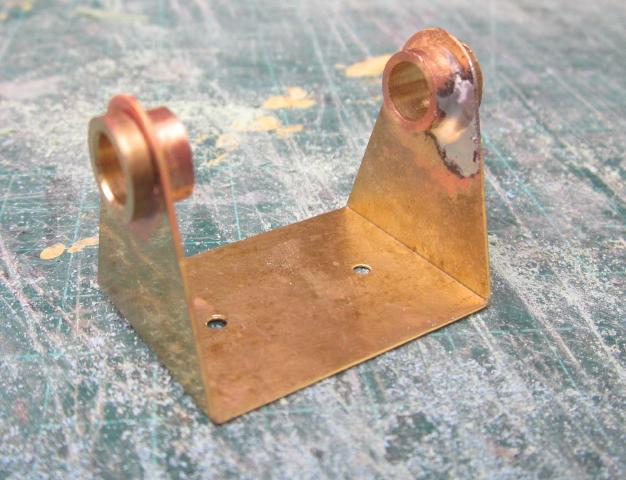
It was a fairly simple process to solder a short length of brass rod along the centre line of one bracket on each coach and drill a hole at either end of the rod.
Image

The brackets were then re-attached to the body with a couple of self-tappers, not fully tightened, so the brackets could wiggle.
<object width="640" height="480"><param name="movie" value="http://www.youtube.com/v/4d4NtVFDfR8?ve ... ram><param name="allowFullScreen" value="true"></param><param name="allowscriptaccess" value="always"></param><embed src="http://www.youtube.com/v/4d4NtVFDfR8?ve ... n_US&rel=0" type="application/x-shockwave-flash" width="640" height="480" allowscriptaccess="always" allowfullscreen="true"></embed></object>

She is now one of my most reliable runners and I'll often get her out to run a quick passenger service when the fancy takes me.

Rik
------------------------
Peckforton Light Railway - Blog Facebook Youtube

Gralyn

Post by Gralyn » Sun Sep 13, 2015 10:56 am

mightymax:113403 wrote:Love the look of that little engine. Where did it come from and what powers it?
The small green loco is a Garden Railway Specialist generic Hunslet kit with their 0-4-0 chassis which can be bought with either 45mm or 32mm gauge. The chassis has a MFA como motor . My loco is battery powered 10 AA rechargeable batteries in the saddle tank and Deltang R/C.

User avatar
dougrail
Driver
Driver
Posts: 1535
Joined: Mon Mar 14, 2011 5:11 pm
Location: Salopia; on the edge of Arcadia

Post by dougrail » Sun Sep 13, 2015 11:47 am

Sprung stock?

I have a whole rake of coaches with sprung axleboxes.

I have also just invested two hundred dorrah' on a fleet of Newqida coaches, GRS steeler wheels and Accy couplers - I hop that they will not derail!

Post Reply

Who is online

Users browsing this forum: No registered users and 0 guests