A Wickham trolley

Re: A Wickham trolley
Thanks Phil, that's the first picture I've seen of the T/T itself although I haven't looked specifically. I can see it has 4 separate parts that slot together for use but I'm still not sure how it was carried around on the trolley though. Might look into it a bit further when I've got the basic machine sorted.
Philip
Re: A Wickham trolley
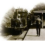
I've been doing some digging and although I've not found anything particularly relevant to my project, I did come across this amazing Wickham trolley version exported to India in 1932. This has to be up Peter Butler's street?
http://hgcreasey.co.uk/wickham-ware/wic ... rks-no-494
Whilst on this site, take a look at the other headings, there are some amazing road vehicles that are crying out to be modeled.
http://hgcreasey.co.uk/wickham-ware/wic ... rks-no-494
Whilst on this site, take a look at the other headings, there are some amazing road vehicles that are crying out to be modeled.
Philip
-
Peter Butler

- Driver

- Posts: 5243
- Joined: Sun Sep 09, 2012 10:33 pm
- Location: West Wales
Re: A Wickham trolley
Too right Philip, that is a posh Wickham and I love it! The bucket seating looks really comfy too.
The best things in life are free.... so why am I doing this?
Re: A Wickham trolley
On the subject of the turntable, I've found this video showing how its done.
https://www.youtube.com/watch?v=Mrf0tpoRES8
https://www.youtube.com/watch?v=Mrf0tpoRES8
Philip

Re: A Wickham trolley
Well done for finding that! It really is as simple as it appeared to be then. Presumably there were variations in the central pivot point employed, hence the differences in the photos.philipy wrote: ↑Sun Mar 28, 2021 10:56 am On the subject of the turntable, I've found this video showing how its done.
https://www.youtube.com/watch?v=Mrf0tpoRES8
Personally, at our scales, I think 'the hand of Dog' is easier
Phil
Sporadic Garden Railer who's inconsistencies know no bounds
My Line - https://gardenrails.org/forum/viewtopic ... 41&t=11077
Sporadic Garden Railer who's inconsistencies know no bounds
My Line - https://gardenrails.org/forum/viewtopic ... 41&t=11077


Re: A Wickham trolley
I'm so glad you agree with Philip --- the India Wickham is an absolute MUST for you 
Waldeker EisenBahn
Re: A Wickham trolley
Ok, a small update.
A few years ago, Rik posted about how he used a recordable greetings card module to provide sound to one of his small loco's, as part of a series of sound "How to's..".
At the time I thought that it might come in handy one day so I acquired a similar unit, put it in the cupboard and promptly forgot all about it. Every now and again I came across this collection of bits in a bag and couldn't quite remember what it was! However, I did remember Rik's articles and wondered if it might be helpful for the Wickham, so I looked it up last week and lo and behold, it jogged my memory about my bag of bits.
About 2/3 the way down this page: https://riksrailway.blogspot.com/search?q=sound
To cut a long story short, I lashed up my bag of bits following Rik's instructions, but it didn't work.... until I noticed that after all this time one of the batteries had leaked.
  A new power supply and it worked exactly as described - thanks Rik.
I had hopes of putting the circuit board in the engine bay, but it may be a bit of a squeeze and would result in running wiring around, and since the speaker has to go under the trolley roof, I decided that the board may as well go up there as well.
So I designed and printed the following housing to fit the curve of the roof underside: From left to right - the speaker is obvious, the circuit board is next to it and the small push button switch allows the sound to be turned on/off completely. The two wired objects at the top of the picture are the mic and record button and will be removed in due course, and the twisted pair at the bottom are the power supply, which will need to be run down to the main battery.

The mic and record buttons are only still attached because I'm not happy with the sound that I've downloaded and edited from a Youtube video and I will want to redo it when I find a better one.
A few years ago, Rik posted about how he used a recordable greetings card module to provide sound to one of his small loco's, as part of a series of sound "How to's..".
At the time I thought that it might come in handy one day so I acquired a similar unit, put it in the cupboard and promptly forgot all about it. Every now and again I came across this collection of bits in a bag and couldn't quite remember what it was! However, I did remember Rik's articles and wondered if it might be helpful for the Wickham, so I looked it up last week and lo and behold, it jogged my memory about my bag of bits.
About 2/3 the way down this page: https://riksrailway.blogspot.com/search?q=sound
To cut a long story short, I lashed up my bag of bits following Rik's instructions, but it didn't work....
I had hopes of putting the circuit board in the engine bay, but it may be a bit of a squeeze and would result in running wiring around, and since the speaker has to go under the trolley roof, I decided that the board may as well go up there as well.
So I designed and printed the following housing to fit the curve of the roof underside: From left to right - the speaker is obvious, the circuit board is next to it and the small push button switch allows the sound to be turned on/off completely. The two wired objects at the top of the picture are the mic and record button and will be removed in due course, and the twisted pair at the bottom are the power supply, which will need to be run down to the main battery.
The mic and record buttons are only still attached because I'm not happy with the sound that I've downloaded and edited from a Youtube video and I will want to redo it when I find a better one.
Philip
Re: A Wickham trolley
Looking good. I did the same to my little HGLW steeple cab loco. In the end I stuck with the sound I first found, because I realised the low power and speaker wouldn't show a more realistic sound effect in a better lightphilipy wrote: ↑Mon Mar 29, 2021 3:33 pm Ok, a small update.
A few years ago, Rik posted about how he used a recordable greetings card module to provide sound to one of his small loco's, as part of a series of sound "How to's..".
At the time I thought that it might come in handy one day so I acquired a similar unit, put it in the cupboard and promptly forgot all about it. Every now and again I came across this collection of bits in a bag and couldn't quite remember what it was! However, I did remember Rik's articles and wondered if it might be helpful for the Wickham, so I looked it up last week and lo and behold, it jogged my memory about my bag of bits.
About 2/3 the way down this page: https://riksrailway.blogspot.com/search?q=sound
To cut a long story short, I lashed up my bag of bits following Rik's instructions, but it didn't work....
I had hopes of putting the circuit board in the engine bay, but it may be a bit of a squeeze and would result in running wiring around, and since the speaker has to go under the trolley roof, I decided that the board may as well go up there as well.
So I designed and printed the following housing to fit the curve of the roof underside: From left to right - the speaker is obvious, the circuit board is next to it and the small push button switch allows the sound to be turned on/off completely. The two wired objects at the top of the picture are the mic and record button and will be removed in due course, and the twisted pair at the bottom are the power supply, which will need to be run down to the main battery.
The mic and record buttons are only still attached because I'm not happy with the sound that I've downloaded and edited from a Youtube video and I will want to redo it when I find a better one.
Phil
Sporadic Garden Railer who's inconsistencies know no bounds
My Line - https://gardenrails.org/forum/viewtopic ... 41&t=11077
Sporadic Garden Railer who's inconsistencies know no bounds
My Line - https://gardenrails.org/forum/viewtopic ... 41&t=11077
-
Peter Butler
- Driver
- Posts: 5243
- Joined: Sun Sep 09, 2012 10:33 pm
- Location: West Wales
Re: A Wickham trolley
Problem solved..... A Wickham Trolley with reverse!
https://www.youtube.com/watch?v=hdfmJ2- ... 9w&index=1
https://www.youtube.com/watch?v=hdfmJ2- ... 9w&index=1
The best things in life are free.... so why am I doing this?
Re: A Wickham trolley
Thanks Peter. Yes the later ones with Ford etc engines and proper gearboxes did have reverse, but that was roughly from WW2 onwards. However the early ones from the 1920's used JAP V motorcycle engines with no reverse.
Philip
Re: A Wickham trolley
It's been a bit of a job this past couple of weeks as I struggled to fit all that I wanted into the confined space in the Wickham. The sound unit was fairly simple, concealed under the roof as shown above, however within the engine housing I needed to fit: two batteries with protection board, voltage regulator, R/C receiver, on/off switch, motor, gears, charge sockets, fuse and, of course, bits of wire to join it all together - all in a space that is 118L x 21W x 30H maximum.
The whole lot needed to be mounted on or in a frame that would fit within those dims so that it was removable from the body so that immediately reduced the usable width even more.
I remembered a series of articles in SMT from several years ago in which Mike Jeffries repurposed various low cost R/C units, and managed to dig it out - SMT 157 February 2016. These units are still available on ebay although the price has risen somewhat over the years, so I shelled out my £3-69 and when it arrived I was pleased to find that it did function exactly as Mike had described.

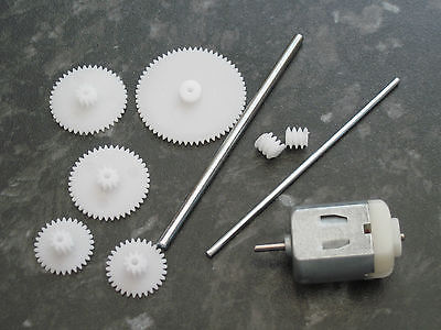
In order to get the motor concealed between the frames and make maximum use of the space, I would need a 2 stage gearbox to get down to the driven axle, which would also have the advantage of keeping the top speed restricted. Given the small size of the wheels (20mm) it was a bit of a juggle to keep everything concealed, even in theory! However, again on good old fleabay, I found a model shop selling a 3v motor with a selection of nylon gears, for £3-95.
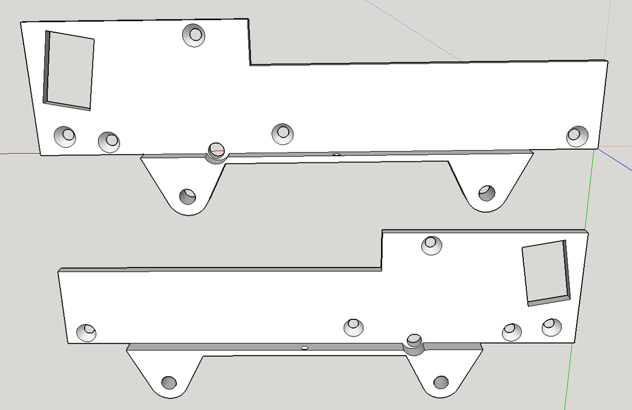
A little bit of juggling around in Sketchup showed that it would just allow me to do what was needed. The middle gear does protrude slightly below the chassis but should be virtually invisible behind the wheels on a such a low slung vehicle.
More to follow.
The whole lot needed to be mounted on or in a frame that would fit within those dims so that it was removable from the body so that immediately reduced the usable width even more.
I remembered a series of articles in SMT from several years ago in which Mike Jeffries repurposed various low cost R/C units, and managed to dig it out - SMT 157 February 2016. These units are still available on ebay although the price has risen somewhat over the years, so I shelled out my £3-69 and when it arrived I was pleased to find that it did function exactly as Mike had described.
In order to get the motor concealed between the frames and make maximum use of the space, I would need a 2 stage gearbox to get down to the driven axle, which would also have the advantage of keeping the top speed restricted. Given the small size of the wheels (20mm) it was a bit of a juggle to keep everything concealed, even in theory! However, again on good old fleabay, I found a model shop selling a 3v motor with a selection of nylon gears, for £3-95.
A little bit of juggling around in Sketchup showed that it would just allow me to do what was needed. The middle gear does protrude slightly below the chassis but should be virtually invisible behind the wheels on a such a low slung vehicle.
More to follow.
Philip
Re: A Wickham trolley
Glad it's proved useful. I've not discovered a way of overcoming the half second pause when it recycles, but considering the price it's not too intrusive.
Rik
Re: A Wickham trolley
I've only heard it on the bench so far, but I suspect that out in the garden with all the general noise of birds, wind, etc, it won't really notice at all.
Philip


Re: A Wickham trolley
Philip, I have one of the RF controls that came with a set of LED lights, and I have to admit I have struggled to get it to work, new batteries all round and it has been very sporadic, but will give it another go 

Re: A Wickham trolley
So the next step was to 3D print the gearbox/chassis. No real problem with that although I had to do it several times, partly because after each prototype print I thought, "Hmm, I should have...", and partly because the issue of print shrinkage made it a bit tricky to precisely position the intermediate gear - the gears have very small teeth which leaves little room for error.
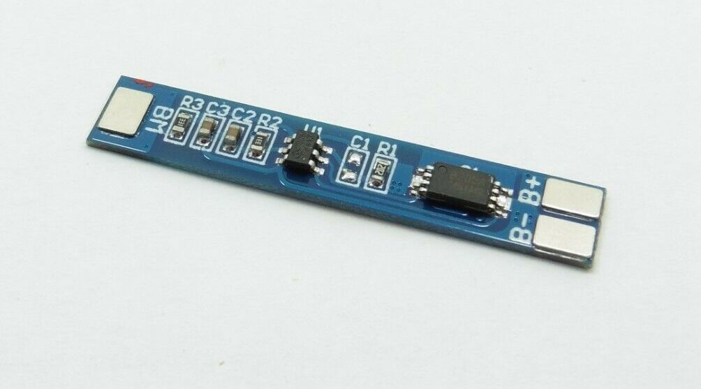
The r/c receiver requires a minimum of 5.4v to function so the obvious choice for batteries was a pair of Li-ions giving 7.4v total. I managed to find two solder tagged 16340 3.7v Li-Ion batteries which I could make into a battery pack which included a very small (27 x 5.7 x 1.6mm) protection board, which I fitted inside the heatshrink sleeve.

This battery pack fitted neatly on top of the the gearbox chassis unit, the width being identical and by reducing the height of the chassis ( one of the protype mods I mentioned above) it fitted within the height constraint.
The Rx is 41 x 13 x 5mm and this fits neatly under the battery pack between the frames, although as Mike Jeffries suggested, it was necessary to remove and replace the rx heat shrink sleeve and replace the heavy wires with thinner more flexible ones. At the same time, I rerouted them to all come out of one end and used different coloured wires for the supply and control connections.


The r/c receiver requires a minimum of 5.4v to function so the obvious choice for batteries was a pair of Li-ions giving 7.4v total. I managed to find two solder tagged 16340 3.7v Li-Ion batteries which I could make into a battery pack which included a very small (27 x 5.7 x 1.6mm) protection board, which I fitted inside the heatshrink sleeve.
This battery pack fitted neatly on top of the the gearbox chassis unit, the width being identical and by reducing the height of the chassis ( one of the protype mods I mentioned above) it fitted within the height constraint.
The Rx is 41 x 13 x 5mm and this fits neatly under the battery pack between the frames, although as Mike Jeffries suggested, it was necessary to remove and replace the rx heat shrink sleeve and replace the heavy wires with thinner more flexible ones. At the same time, I rerouted them to all come out of one end and used different coloured wires for the supply and control connections.
Philip
Re: A Wickham trolley
So far so good and much as I had expected, but now for the bits that I didn't quite know what to do with - the sockets, the fuse, the switch and the voltage regulator.
In my box of bits I found a small Voltage Reg module which was by chance exactly 15mm wide and fitted perfectly on top of the top frame spacer over the motor, held in place by piece of double sided tape.
The voltage regulator is essential because the battery is nominally 7.4v and the motor is only 3 volts. The original article suggested using a string of diodes to drop the voltage, but apart from being a messy waste of space, it simply doesn't seem the right way to go about it, plus of course the regulator will compensate for battery voltage dropping.
The battery balance charge plug on a short lead will wrap down the side of the gearbox frame out of the way inside the outer housing, so thats not a problem.
This leaves the main charge socket, switch and fuse needng homes. The Rx board is 35mm long and between the frame spacers under the battery pack there is a space about 53mm long, which leaves me with about 18mm spare, just enough for the socket mounted vertically. Half an hour later and I had printed an L-shaped replacement spacer with a hole in it for the socket. I had to bend the socket tags down level with it's body to leave room for the battery on top and this leaves a small gap behind the socket is just big enough for the auto reset fuse!
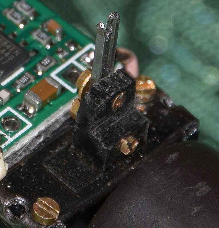
All that just leaves the on/off switch. Of course sometimes it's unavoidable, but I hate seeing switches visibly mounted on external frames, footplates, etc. In this case there isn't even that much luxury and I've been contemplating having to surface mount it and try to disguise it as a toolbox or something. The trouble with that is that it would have the switch mounted on the body not the underframe with all the electrics.
Then good fortune smiled on me again. In the photos, some of this early design of Trolley had a gap in the top boarding of the engine housing, just in front of the drivers seat. I'm not sure what it is for in the real thing, but there is a lever of some sort protruding up from it, gear lever perhaps? I had already left this gap when I printed the body parts and when I looked through this gap, after offering the works up underneath, low and behold there was a gap between the motor and the L-shaped spacer, which lined up almost perfectly with my top gap. Moreover, when I measured the actual space I found that a few strokes of a file could reduce the body of a slide switch slightly to fit between the frames. The switch knob was not quite lined up, but I sawed down from the top and reduced the width by about 50% so that it now slides in the gap. A little bit of work with a short piece of 4mm scale bullhead rail and a couple of 14BA nuts and bolts, gives me a 'knob extension' which allows the switch to function from above the body whilst being fixed to the works.
In my box of bits I found a small Voltage Reg module which was by chance exactly 15mm wide and fitted perfectly on top of the top frame spacer over the motor, held in place by piece of double sided tape.
The voltage regulator is essential because the battery is nominally 7.4v and the motor is only 3 volts. The original article suggested using a string of diodes to drop the voltage, but apart from being a messy waste of space, it simply doesn't seem the right way to go about it, plus of course the regulator will compensate for battery voltage dropping.
The battery balance charge plug on a short lead will wrap down the side of the gearbox frame out of the way inside the outer housing, so thats not a problem.
This leaves the main charge socket, switch and fuse needng homes. The Rx board is 35mm long and between the frame spacers under the battery pack there is a space about 53mm long, which leaves me with about 18mm spare, just enough for the socket mounted vertically. Half an hour later and I had printed an L-shaped replacement spacer with a hole in it for the socket. I had to bend the socket tags down level with it's body to leave room for the battery on top and this leaves a small gap behind the socket is just big enough for the auto reset fuse!
All that just leaves the on/off switch. Of course sometimes it's unavoidable, but I hate seeing switches visibly mounted on external frames, footplates, etc. In this case there isn't even that much luxury and I've been contemplating having to surface mount it and try to disguise it as a toolbox or something. The trouble with that is that it would have the switch mounted on the body not the underframe with all the electrics.
Then good fortune smiled on me again. In the photos, some of this early design of Trolley had a gap in the top boarding of the engine housing, just in front of the drivers seat. I'm not sure what it is for in the real thing, but there is a lever of some sort protruding up from it, gear lever perhaps? I had already left this gap when I printed the body parts and when I looked through this gap, after offering the works up underneath, low and behold there was a gap between the motor and the L-shaped spacer, which lined up almost perfectly with my top gap. Moreover, when I measured the actual space I found that a few strokes of a file could reduce the body of a slide switch slightly to fit between the frames. The switch knob was not quite lined up, but I sawed down from the top and reduced the width by about 50% so that it now slides in the gap. A little bit of work with a short piece of 4mm scale bullhead rail and a couple of 14BA nuts and bolts, gives me a 'knob extension' which allows the switch to function from above the body whilst being fixed to the works.
Philip
Re: A Wickham trolley
Marvellous bit of engineering. Can't wait to see it in action.
Rik
Rik
Re: A Wickham trolley
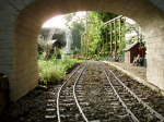
I'm just about to start on the small body fittings etc and in looking at various photos I think I've more or less answered my own question. Most pictures are from the driver's side, but on two which are from the other side, when zoomed in I noticed that both had a couple of strange shaped wooden blocks fixed to the floor. I'm not sure exactly how it works but I strongly suspect that they somehow restrain the the pieces of the the turntable.philipy wrote: ↑Sun Mar 14, 2021 8:34 pmYes, the turntable was a standard fitting although I can't make out where/how they carried it.invicta280 wrote: ↑Sun Mar 14, 2021 8:13 pm I believe they were often kept in a lineside shed equiped with a miniature turntable to put them onto a siding.
- T-T rack.jpg (50.38 KiB) Viewed 4037 times
Philip
Re: A Wickham trolley
Some progress going on behind the scenes. I've managed to produce all the small bits and fittings and they are waiting to be glued on.
I've also produced a crew/PW gang, although for some reason I appear to have recruited little green men from Mars!
I've also produced a crew/PW gang, although for some reason I appear to have recruited little green men from Mars!
- DSC_0001[1].jpg (194.5 KiB) Viewed 3914 times
Philip
Re: A Wickham trolley
Why is one of them doing the hokey kokey?
Rik
Rik
Who is online
Users browsing this forum: No registered users and 2 guests