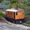

After being inspired by a fellow member here, superbiker_uk, with his fantastic model of a MSR plantation locomotive (see a full account of how MSR came to be and also all of the unique parts involved in building one of these models here: http://gardenrails.myfreeforum.org/about7496.html ) I was lucky enough to find the person who used to make these models and have been in close contact ever since. I owe you a huge thanks superbiker!
Well, my kit arrived Friday just gone (11th October 2013) and I wasted no time at all in getting it together. The plan is to get it to the Exeter garden railway show on the 19th October 2013, running!
Below is an account of the build as it has developed through the last few evenings.
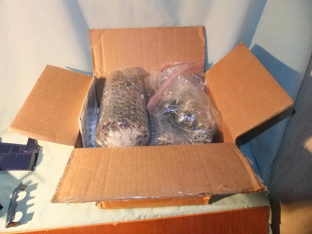
Excited me and a box stuffed with parts
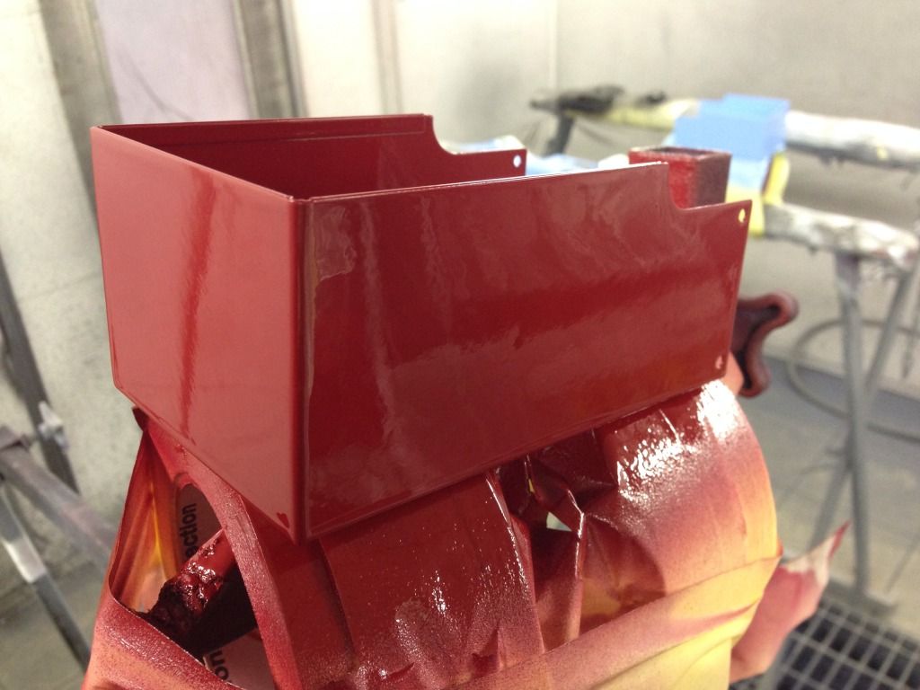
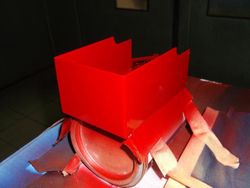
Tender body in galvanised steel
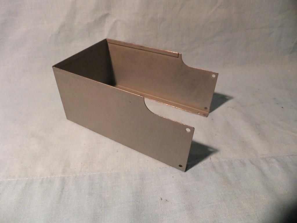
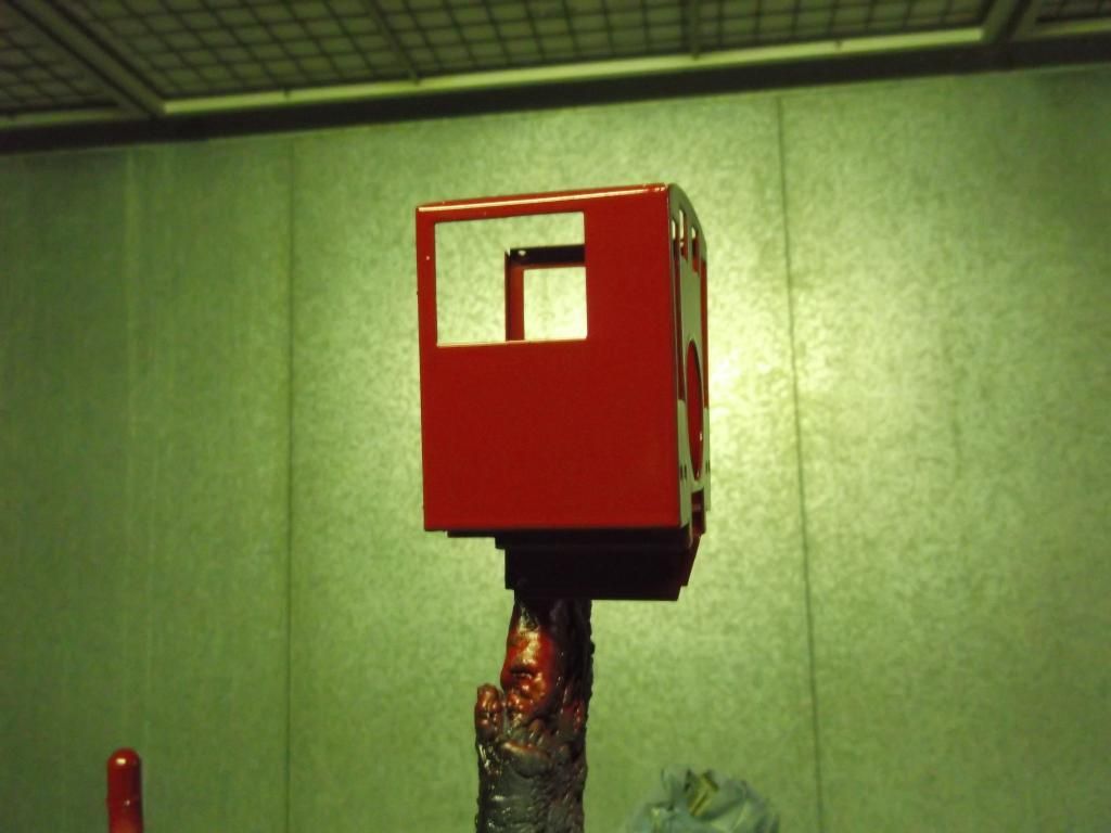
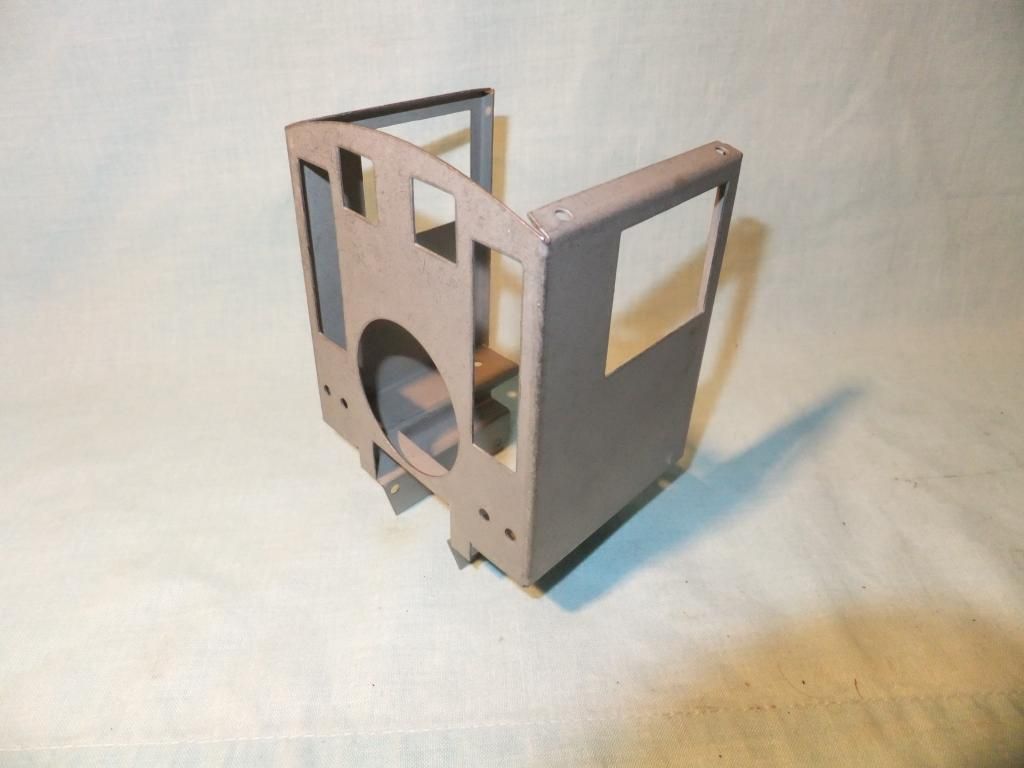
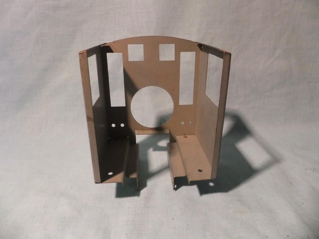
Cab in galvanised steel, this is a work of art!
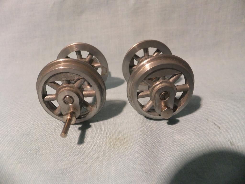
Wheel set
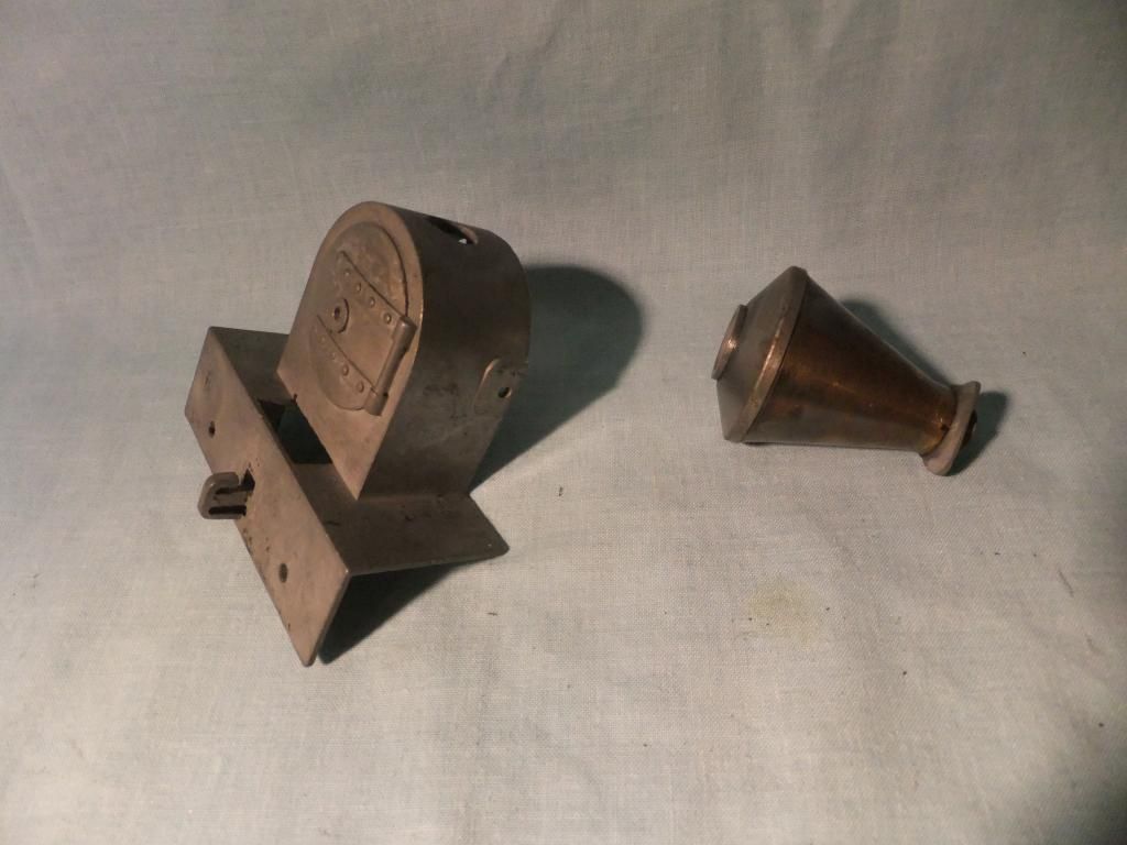
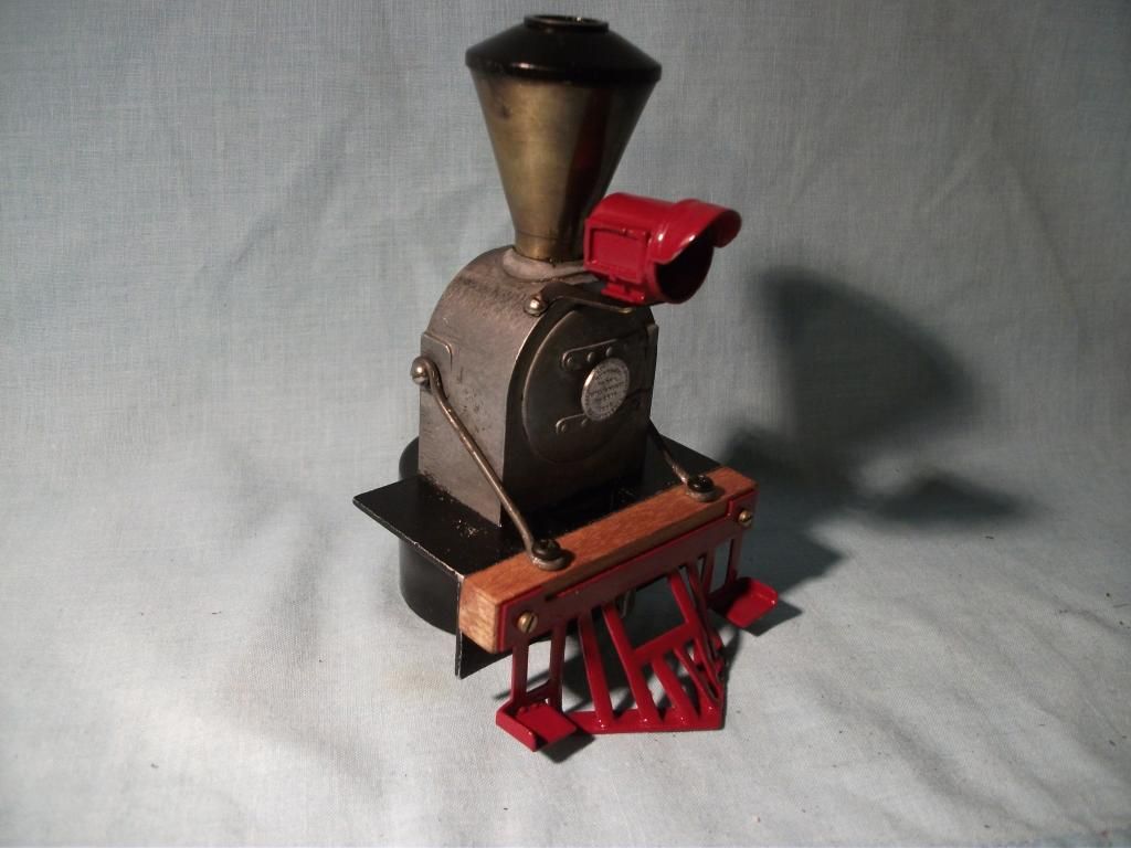
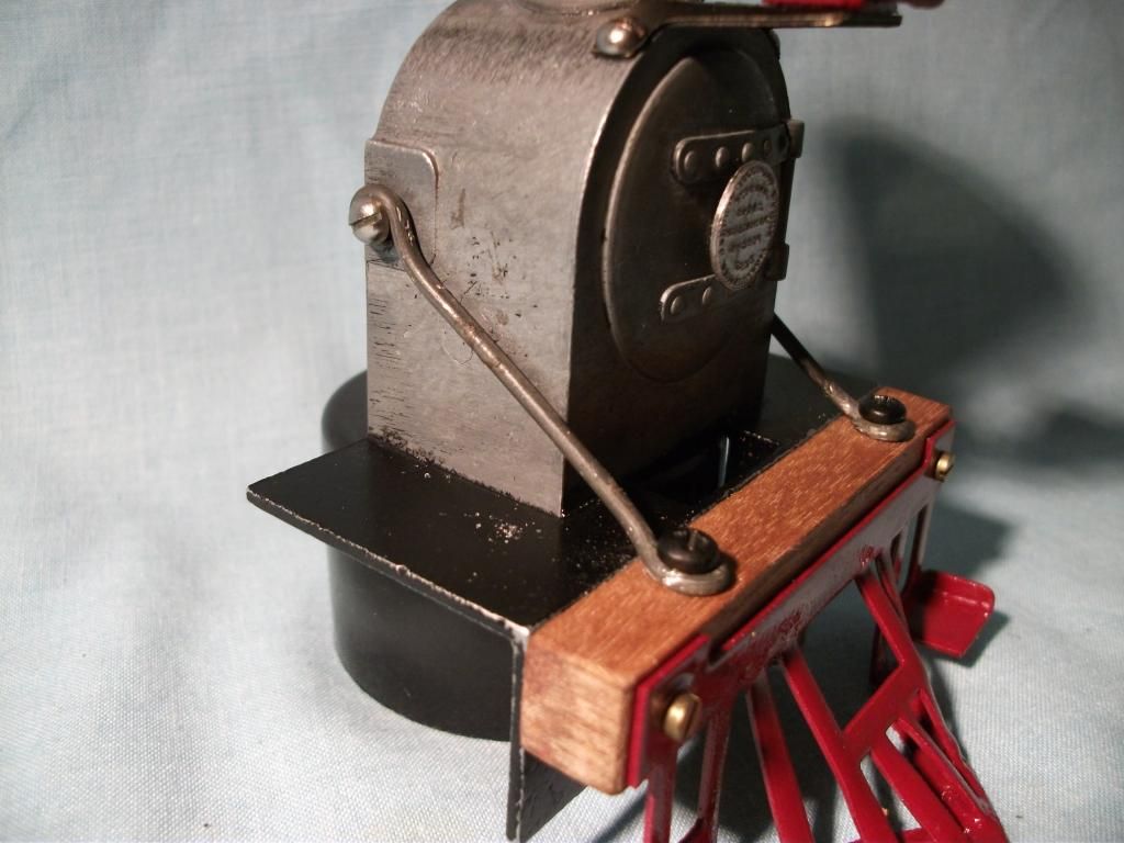
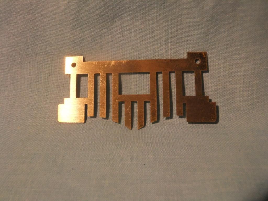
Front cow catcher
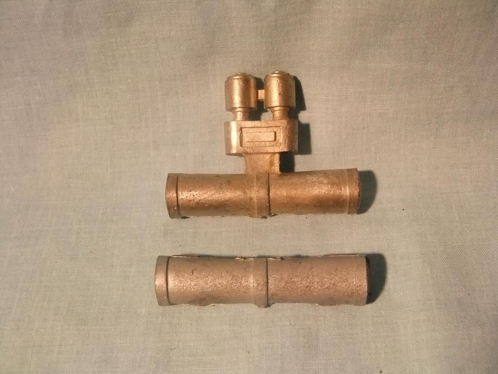
Compressor & tanks
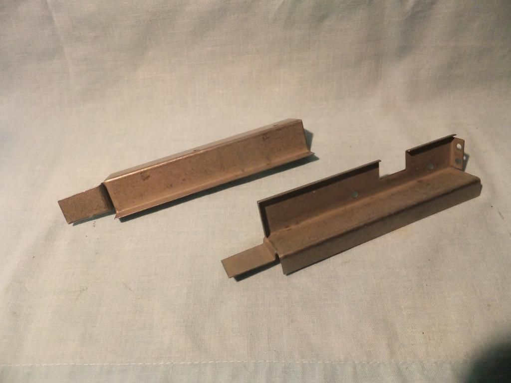
Side runner boards in galvanised steel
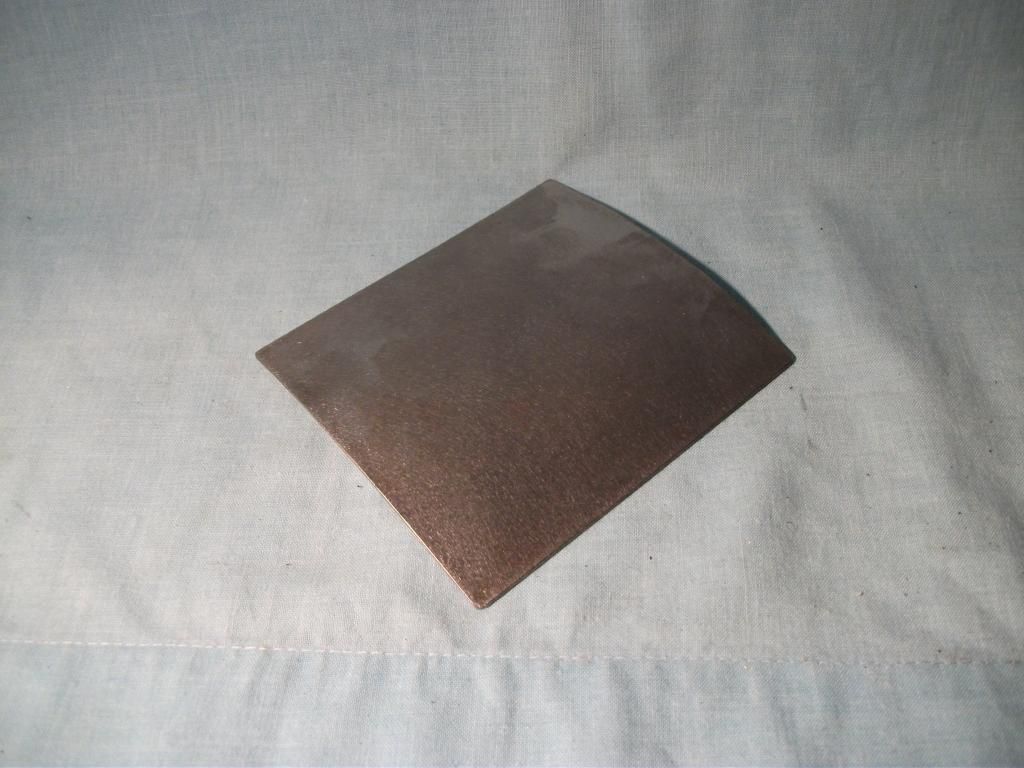
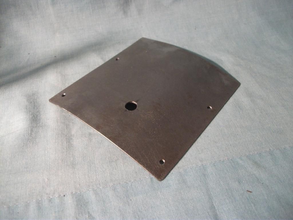
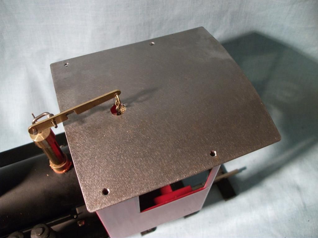
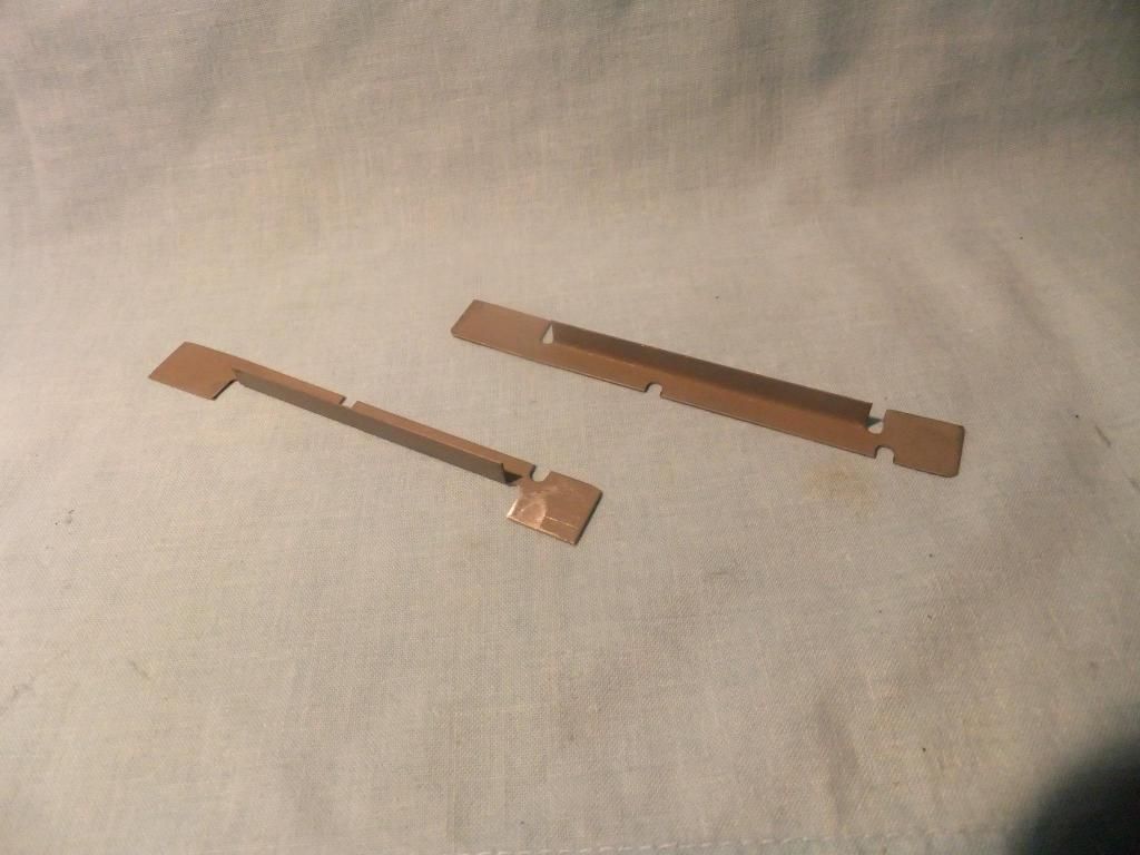
Heat deflectors in galvanised steel
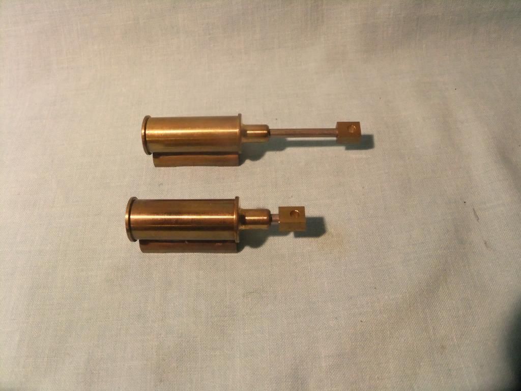
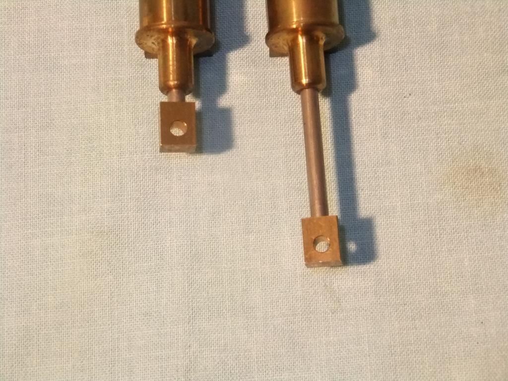
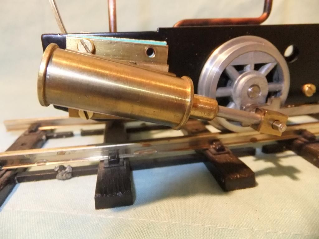
MSR upgraded cylinders
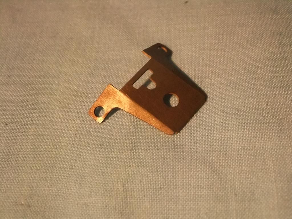
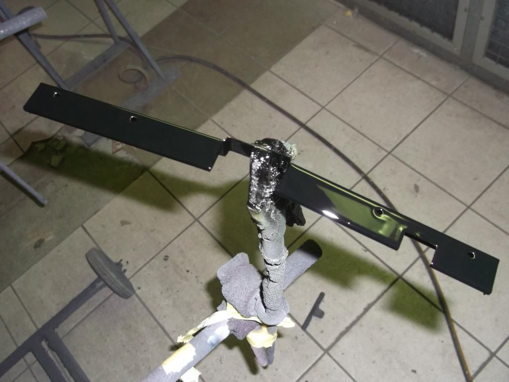
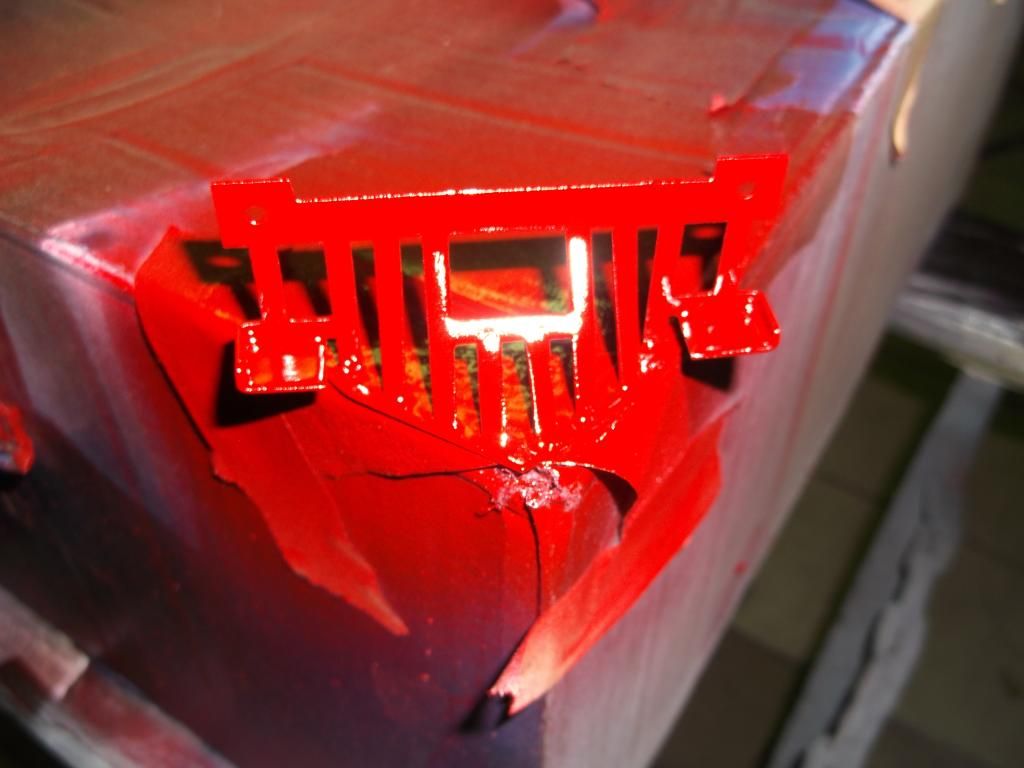
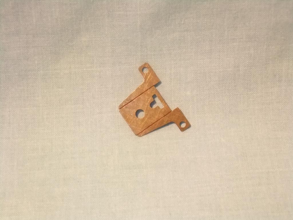
Headlamp bracket
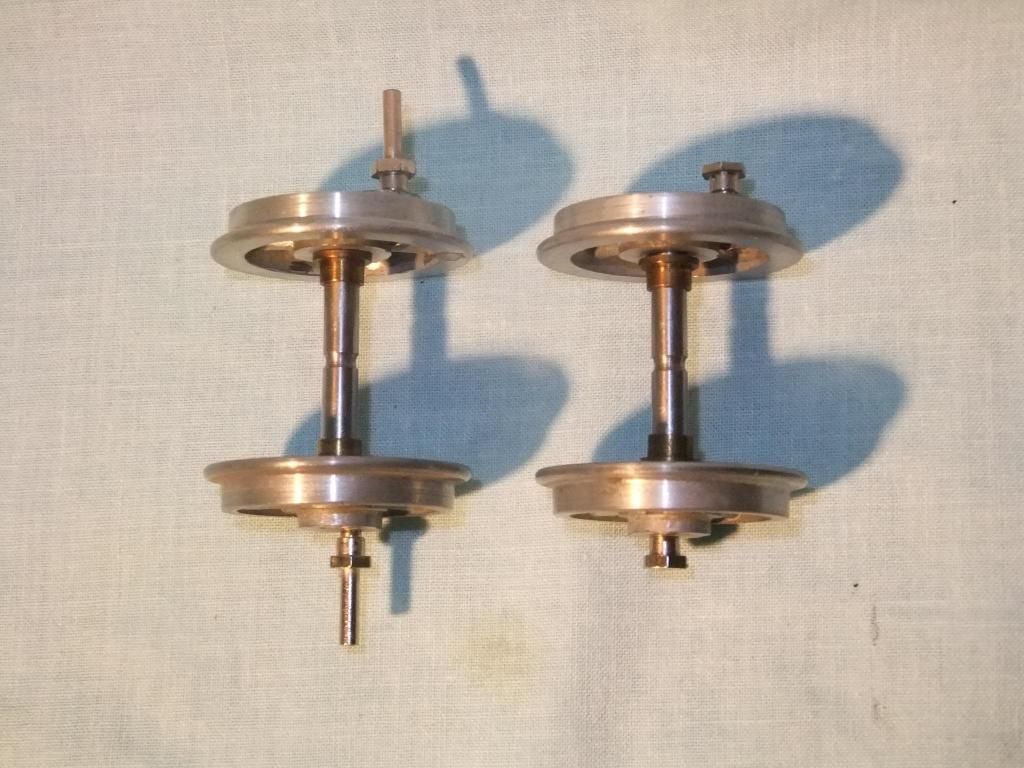
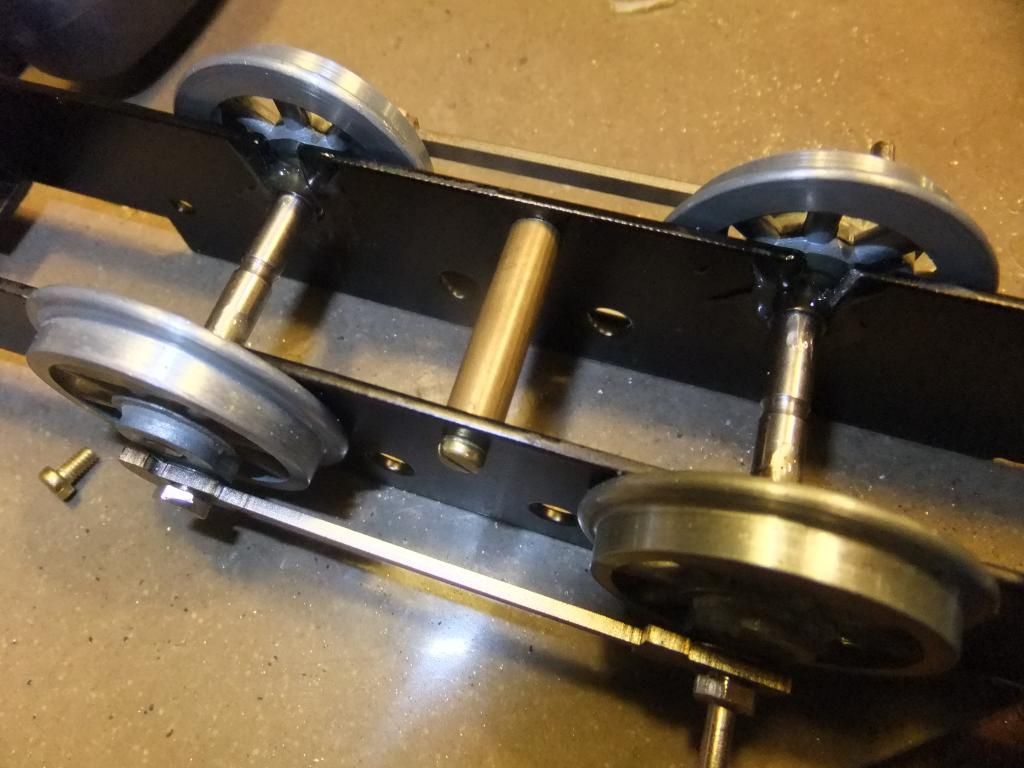
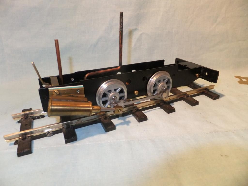
Wheels assembled into a pair of Roy Wood Models 'Janet' frames, just a tad thicker
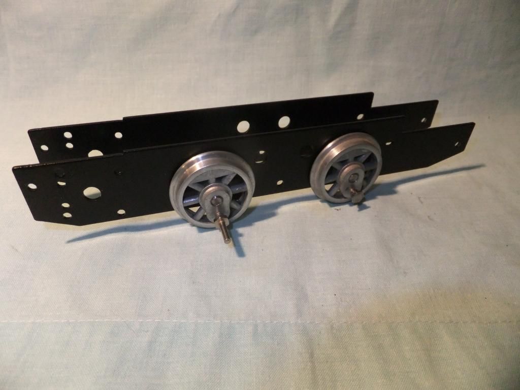
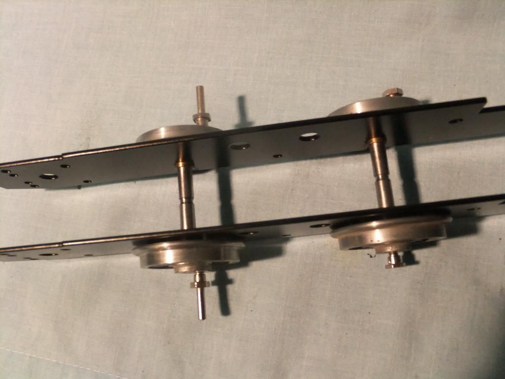
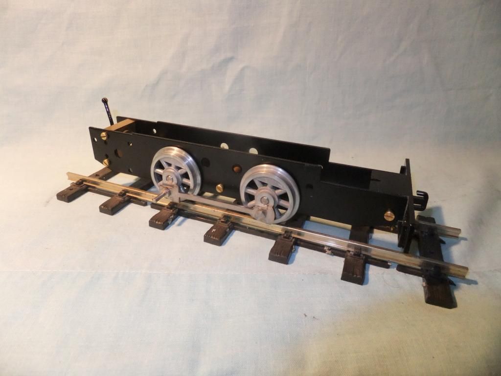
A rolling chassis with an RWM reverser, RWM coupling rods, mss frame spacer and drag beam
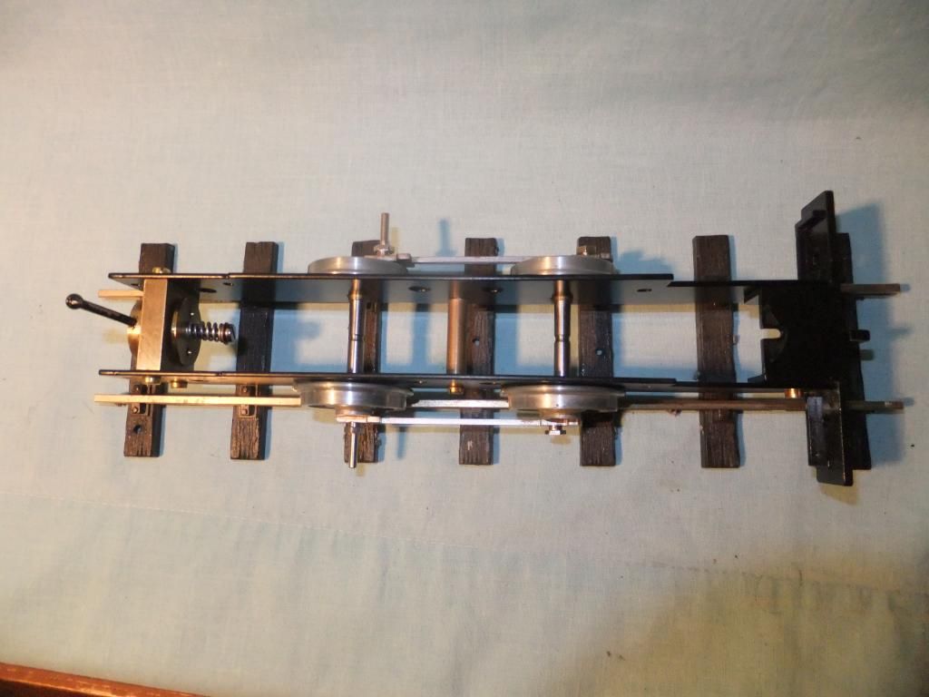
As with all my mamod derived models I 2k epoxied the axle bearings in
The cylinders trial fitted
Beautiful
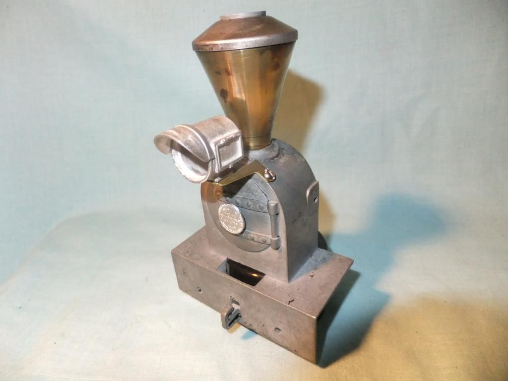
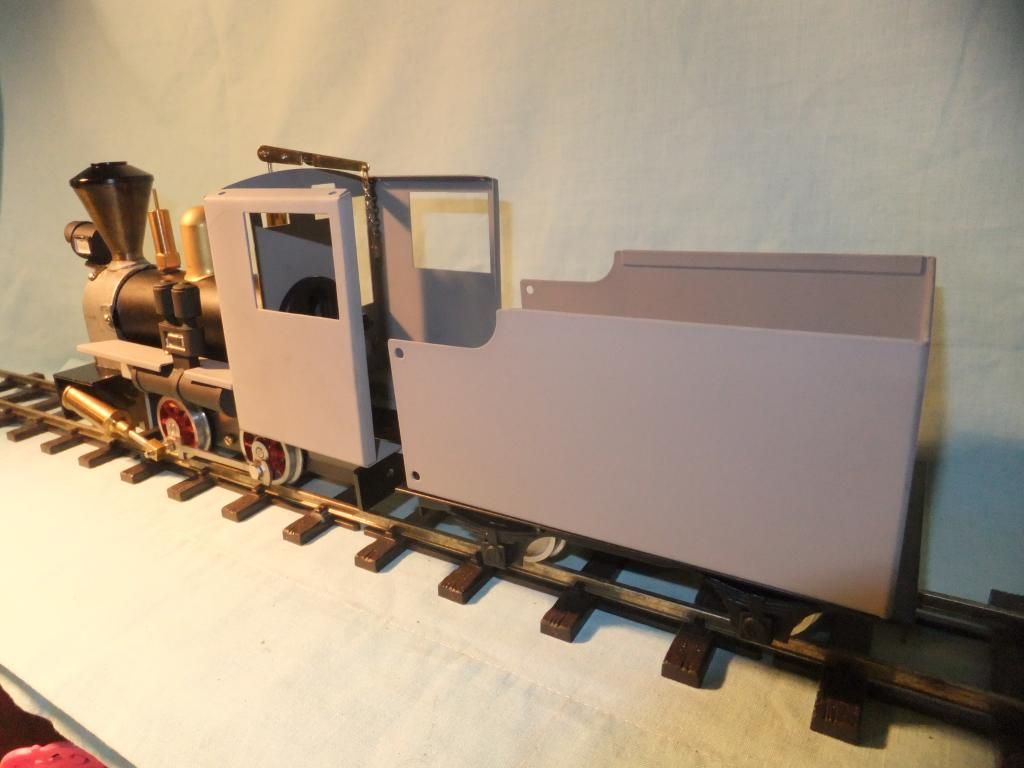
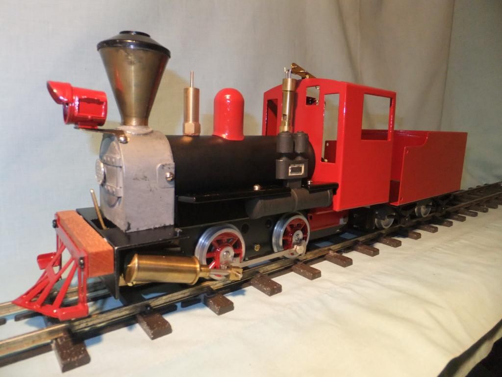
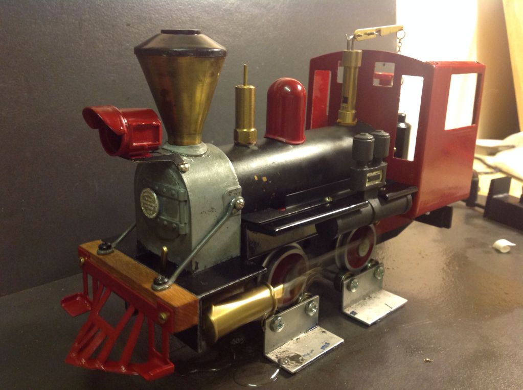
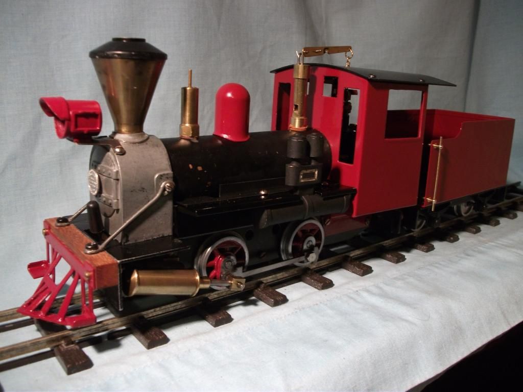
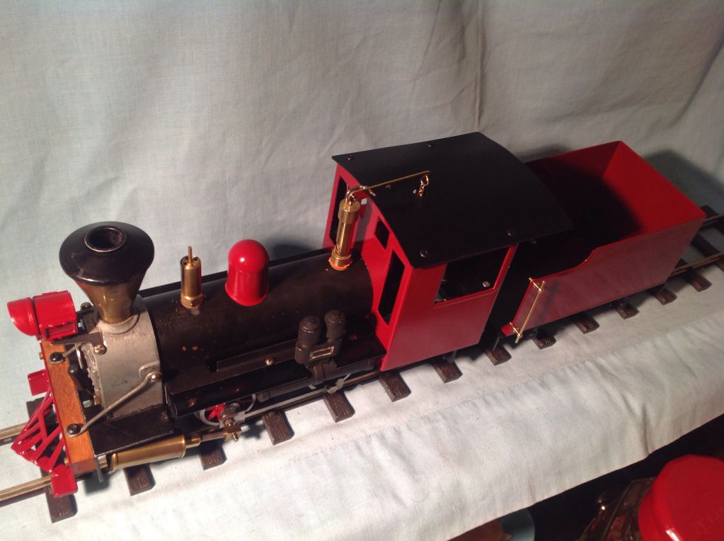
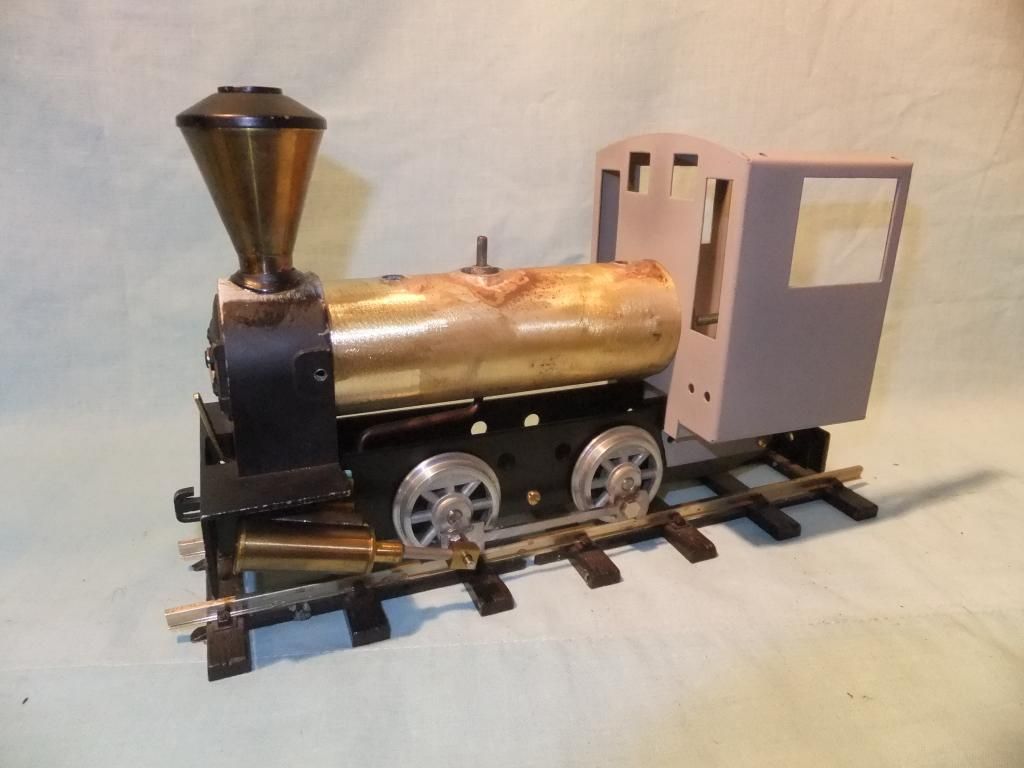
Trial fitting all together with the last 'new' spark arrester smoke box I found with Roy Wood Models and my latest silver soldered boiler.
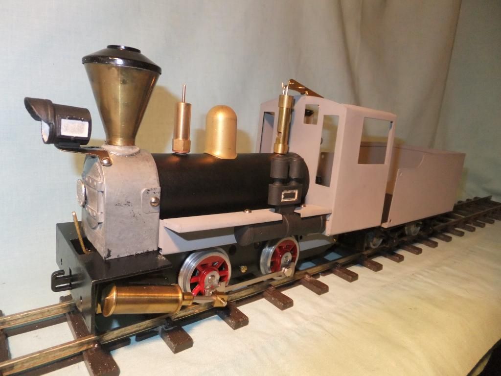
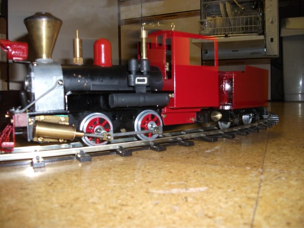
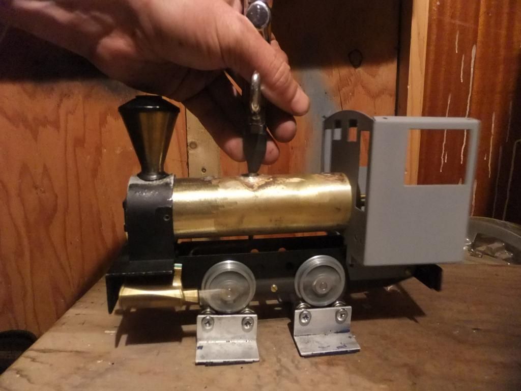
And finally a test run on compressed air.
I welcome all your comments and questions, so please ask away. I am really enjoying this locomotive. It has inspired me to build in a logging area of my line when I eventually move house and lay it.